MCLJ27H023WLAN MODULE
HON HAI Precision Ind. Co., Ltd.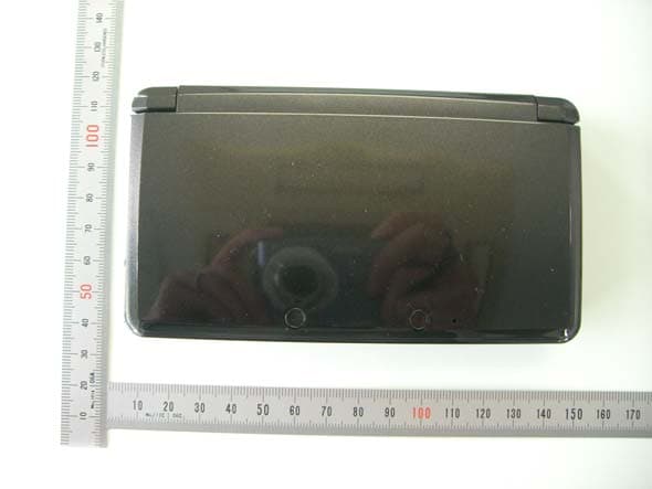
Click to zoom
Application Details
- Equipment Class
- DTS - Digital Transmission System
- Date of Grant
- Apr 16, 2011
- Application Purpose
- Original Equipment
- Date of Application
- Apr 16, 2011
- Equipment Note
- WLAN MODULE
- Frequency Range
- 2412.00000000 - 2462.00000000
- Country
- Taiwan
Documents & Files
Document Text
Text extracted from the exhibit documents filed with the FCC. Open a document above to read the original.
Users Manual
HON HAI PRECISION IND. CO., LTD. HSINCHU SCIENCE PARK BRANCH OFFICE 1 J27H023 WLAN MODULE USER’S MANUAL HON HAI PRECISION IND. CO., LTD. HSINCHU SCIENCE PARK BRANCH OFFICE 2 Contents INTRODUCTION................................................................................................................................................................... 3 1.1 WLAN FEATURES.......................................................................................................................................................... 3 1.2 FCC NOTICE.................................................................................................................................................................. 3 1.3 CANADA NOTICE............................................................................................................................................................ 4 The information contained in this manual has been verified at the time of this manual printing. The manufacturer reserves the right to make any changes and improvements in the product described in this manual at any time and without notice. All registered trademarks are the property of their respective owners. HON HAI PRECISION IND. CO., LTD. HSINCHU SCIENCE PARK BRANCH OFFICE 3 Introduction The J27H023.00 802.11b/g module provides wireless modem functionality utilizing direct sequence spread spectrum and OFDM/CCK technology. 1.1 WLAN Features Operating Frequency 2412 ~ 2483.5 MHz ISM band Modulation Schemes 802.11: DPSK,DBPSK 802.11g: OFDM, DQPSK, DBPSK and CCK 802.11b: DQPSK, DBPSK and CCK Channel Numbers IEEE 802.11/802.11b compliant: 1 ~ 13 channels for United States, Europe and Japan IEEE 802.11 g compliant: 1 ~ 11 channels for United States, Europe and Japan WLAN Data Rate 802.11g: Up to 54 Mbps with auto fallback to 48, 36, 24, 18, 12, 9 and 6 Mbps. 802.11b: Up to 11 Mbps with auto fallback to 5.5, 2 and 1Mbps. 802.11: Up to 1Mbps and 2Mbps Media Access Protocol CSMA/CA with ACK Antenna Type Single antenna connector for off board antenna Operating Voltage 1.8 VDC and 3.3 VDC Operating Systems Windows 98/Me/2000/XP 1.2 FCC Notice Federal Communication Commission Interference Statement This device complies with Part 15 of the FCC Rules. Operation is subject to the following two conditions: (1) This device may not cause harmful interference, and (2) this device must accept any interference received, including interference that may cause undesired operation. FCC Caution: Any changes or modifications not expressly approved by the party responsible for compliance could void the user's authority to operate this equipment. IMPORTANT NOTE: FCC Radiation Exposure Statement: This equipment complies with FCC radiation exposure limits set forth for an uncontrolled environment. This transmitter must not be co-located or operating in conjunction with any other antenna or transmitter. HON HAI PRECISION IND. CO., LTD. HSINCHU SCIENCE PARK BRANCH OFFICE 4 IMPORTANT NOTE: In the event that these conditions can not be met (for example certain laptop configurations or co-location with another transmitter), then the FCC authorization is no longer considered valid and the FCC ID can not be used on the final product. In these circumstances, the OEM integrator will be responsible for re-evaluating the end product (including the transmitter) and obtaining a separate FCC authorization. End Product Labelling The final end product must be labelled in a visible area with the following: “Contains FCC ID: MCLJ27H023”. Manual Information That Must be Included The OEM integrator has to be aware not to provide information to the end user regarding how to install or remove this RF module in the users manual of the end product which integrate this module. The users manual for OEM integrators must include the following information in a prominent location “ IMPORTANT NOTE: To comply with FCC RF exposure compliance requirements, the antenna used for this transmitter must not be co-located or operating in conjunction with any other antenna or transmitter. 1.3 Canada Notice Industry Canada Statement This device complies with RSS-210 of Industry Canada. Operation is subject to the following two conditions: 1) this device may not cause interference and 2) this device must accept any interference, including interference that may cause undesired operation of the device Caution: Exposure to Radio Frequency Radiation. This device must not be co-located or operating in conjunction with any other antenna or transmitter. Labeling System integrators must include the IC ID on the end product.
Users Manual
OPERATIONS MANUAL NINTENDO 3DS OPERATIONS MANUAL FRANÇAIS Pg. 109ESPAÑOL Pg. 219 NINTENDO 3DS OPERATIONS MANUAL PRINTED IN CHINAMAA-CTR-S-USZ-C073238A NINTENDO OF AMERICA INC. P.O. BOX 957, REDMOND, WA 98073-0957 U.S.A. NEED HELP WITH INSTALLATION, MAINTENANCE OR SERVICE? Nintendo Customer Service SUPPORT.NINTENDO.COM or call 1-800-255-3700 BESOIN D’AIDE POUR L’INSTALLATION, L’ENTRETIEN OU LA RÉPARATION? Service à la clientèle de Nintendo SUPPORT.NINTENDO.COM ou composez le 1 800 255-3700 ¿NECESITAS AYUDA DE INSTALACIÓN, MANTENIMIENTO O SERVICIO? Servicio al cliente de Nintendo SUPPORT.NINTENDO.COM o llama al 1-800-255-3700 Nintendo 3DS system Nintendo 3DS stylus (inserted into the system’s stylus holder) 2 GB SD Memory Card (inserted into the system’s SD Card slot) Operations Manual, Quick-start guides, and other printed enclosures. Nintendo 3DS AC adapter AR Cards Nintendo 3DS charging cradle This product is a precision electronic device that can be damaged by direct physical impact or contact with dust or other foreign material. A protective carrying case (sold separately) may help prevent damage to your Nintendo 3DS™ system. Please carefully read this Operations Manual before setup or use of the Nintendo 3DS system. If, after reading all of the instructions, you still have questions, please visit our customer service area at support.nintendo.com or call 1-800-255-3700. A NOTE ABOUT COMPATIBILITY: The Nintendo 3DS system is only compatible with Nintendo 3DS, Nintendo DSi, and Nintendo DS software. Nintendo 3DS Game Cards are only compatible with the Nintendo 3DS system. Some accessories may not be compatible with the Nintendo 3DS system. Your system includes: Product recycling information: visit recycle.nintendo.com Trademarks are property of their respective owners. Nintendo 3DS is a trademark of Nintendo. © 2011 Nintendo Here is a look at a few of the exciting features of the Nintendo 3DS system! 3D Screen Can display 3D images (see page 22). Circle Pad Allows precise 360 ̊ control for software that includes this feature (see page 13). HOME Button Allows you to access the HOME Menu (see page 13). Touch Screen A touch-sensitive display screen controlled by the stylus (see page 15). 3D Depth Slider Adjust the depth of 3D images (see page 23). ©1998-2011 Nintendo 23 Experience 3D images without the need for special eyewear (page 22).The Nintendo 3DS system includes this built-in software: Take 3D photos with the outer cameras (page 42). Play Nintendo 3DS, Nintendo DS, and Nintendo DSi software (page 31). Nintendo 3DS Game CardsNintendo DS & Nintendo DSi Game Cards Take 3D photos with the built-in cameras and software. Listen to music or record sounds. Create Mii™ characters as alter egos for you and your family and friends. Play augmented-reality games using the AR Cards included with your system and the Nintendo 3DS Camera application. Play a shooting game where your face and your friends’ faces become game characters. Check your play times for software you are using or see the amount of steps you have walked while carrying your Nintendo 3DS with you. Download various software titles to play on your Nintendo 3DS system. NOTE: To use this feature, you must connect to the Internet and perform a system update. See page 63 for more information on setting up a wireless broadband Internet connection. See page 80 for more information on how to do a system update. Outer cameras Only specially designed Nintendo 3DS software titles that support 3D image display will appear in 3D. Nintendo DS and Nintendo DSi software do not support 3D display. Nintendo eShop Free software 3D photos Notifications System updates Other information The Wireless LED lights up when wireless communication is turned on. The Wireless LED illuminates when wireless communication is activated. A message will appear on your notification list (see page 40 for more information on the Notifica- tions application and receiving messges). 45 SpotPass™StreetPass™ The SpotPass feature allows the Nintendo 3DS system to automatically communicate with a nearby wireless LAN access point, enabling it to connect to the Internet and transmit a variety of data. The system can also do this while playing a game or in Sleep Mode (power is on, but the system is closed). To connect to a wireless LAN access point, you will need to configure the Internet settings for your Nintendo 3DS system (see page 63). • Within the service area of a Nintendo Zone or other wireless services, you can connect to the Internet without configur- ing your Internet settings. • System updates may unlock the ability to receive more types of data via SpotPass, depending on the game you are playing. It is recommended that you perform system updates to keep your Nintendo 3DS system current with the latest features (see page 80). • If you turn wireless communication off with the wireless switch, the system will not be able to use the communication features. Keeping your system charged. Your system includes a charging cradle to make charging easy. When not in use, you can put the Nintendo 3DS system in Sleep Mode and keep it in the charging cradle, so it stays fully charged and can still communicate using the SpotPass feature. See page 21 for more information on battery endurance. The StreetPass feature allows the Nintendo 3DS system to automatically search for and communi- cate with other Nintendo 3DS systems and to exchange information with them as you walk by. If you are playing a game, or if the system is in Sleep Mode (turned on but closed) and you pass someone who has enabled StreetPass for the same software, you will exchange data with them. (If you don’t want to allow data exchange, you can disable wireless communication.) If StreetPass is successful... StreetPass settings for Nintendo 3DS software are saved on the system. The data you transmit with StreetPass varies depending on the software using this feature. Each software program has its own StreetPass settings.…
Text truncated - open the document above for the full version.
Users Manual
54 Using Software 55 AR Games “?” AR Card Keep the same distance and angle during game play. Aim the cameras at the AR Card. Star Pics If you place a character AR Card in front of the cameras, the character will appear and you can take a photo. Mii Pics Arrange your Mii in different poses and take photos of your Mii in different settings! AR Shot Hit the ball and try to move it into the goal. ??? These games are unlocked when you have cleared AR Shot. Menu screen Archery Shoot the targets that appear on the screen. Complete this to unlock Mii Pics and AR Shot. When you complete AR shot, something more will be unlocked! Using Software AR Games AR Games You can start AR Games from the HOME Menu. These games use AR Cards that are included with your Nintendo 3DS system. Using the outer cameras, the system can read the AR Cards and make magic happen! AR Cards display game stages or characters that can be recognized by the cameras. Check your surroundings... When playing AR Card games, you may have to move around the area while holding the Nintendo 3DS system. Make sure you have enough room, and hold the system firmly with both hands while playing. AR Cards Your Nintendo 3DS system includes six AR Cards. You use the “?” AR card to start game play. Character AR Cards Use these cards when playing Star Pics (see next page). NOTE: If you are not playing Star Pics, do not use these cards and the “?” AR Card together. IMPORTANT: If an AR Card becomes damaged or dirty, the cameras may not be able to read it. If you lose an AR Card, or if it becomes unreadable, you can download AR Card images from support.nintendo.com/ARcards and then print the images in color and use them as replacement cards. Playing AR Card games Place the “?” AR Card on a flat, well-lit surface and keep it within the view of your system’s outer cameras at the correct distance and angle, as described below. Follow the directions, and an on-screen menu should appear above the image of the AR Card. Aim the crosshair at the game you would like to play and then press to make your selection. NOTE: Press START to exit the game and return to the menu screen. If an AR Card isn’t recognized by the cameras, check the following conditions: • Check the distance and the angle. The cameras can’t recognize the card if the distance is too close. • Make sure the card is centered on the screen. • Make sure your game play area is well-lit. • Make sure a bright light source is not reflecting off the surface of the card. • Make sure the camera lenses are clean. • Make sure the card is not damaged or dirty. 14” (35cm) 30 ̊ 56 Using Software 57 FACE RAIDERS Face Raiders Play Select a previously saved face and begin a game. You can also take a new face photo and then begin the game. Face photos taken with Nintendo 3DS Camera may also randomly appear in the game. NOTE: If you have a photo that you do not want used in Face Raiders, you can delete the photo. Show a Friend! Choose among serveral short stages designed to quickly introduce your friends to the game. Take photos of each other’s faces and begin the game. Face Collection You can view, edit, and delete previously saved faces. NOTE: To edit, select a face and then select Face Settings. Using Software Face Raiders Face Raiders You can start Face Raiders from the HOME Menu. Face Raiders puts your face and your friends’ faces in the game! You will need to take at least one face photo to play (see page 42 for more information on taking photos). Check your surroundings... In Face Raiders, you will move around with the Nintendo 3DS system and aim at the targets. Make sure you have enough room to move around freely, and hold the system firmly with both hands while playing. Playing Face Raiders 1 Select Play. Choose an item using the Circle Pad and then press . 2 Take a photo of a face and begin the game. • When taking a face photo, a guide will be displayed. Line up the face with the guide on the upper screen. When the face is recognized, the game will begin. (For tips on facial recognition, see page 96.) • If the face is not automatically recognized, you can manually take the photo by pressing or . Clearing a game and saving photos When you complete a game, you can save the face photo. The more face photos you save, the more levels you can open up. • You can press or as you progress through the game to save an image of the upper screen, which you can view later in the Nintendo 3DS Camera application. • To end a stage and return to the stage selection screen, first press START to suspend your game, then select Quit. • When you reach the maximum number of face photos, you can delete some photos to make room for new face photos. 58 Using Software 59 Activity Log Tap, hold, then slide Tap or to change the time scale that is displayed between days, weeks, months, and years. Tap this option to display the records for the day, week, month or year. Using Software Activity Log Activity Log Switch between step count and play time. Control dial Slide the dial left or right to change the displayed day, week, month, or year. Switch between graph display or activity lists. Activity lists will display playing times for each software title. Scroll the list by tapping or on the lower screen. Software Library Tap a software icon to display information about that software on the upper screen. Turning pages To turn pages, slide the stylus to the left or right, or tap / . Moving icons Tap and hold the stylus on an icon, and then you can slide it to a new position. Deleting icons Tap here to delete the selected icon. • Icons displayed in the Daily Log will not be deleted. • If you play the same software again after deleting its icon, your playing times and other information from before deleting its icon will be retained and added to its displayed figures. Displaying rankings Tap here to see various rankings of all the soft- ware you have played to date. To change the ranking being displayed, tap Change Order. • The number of st…
Text truncated - open the document above for the full version.
Attestation Statements
Date: April 15, 2011 Federal Communications Commission 7435 Oakland Mills Road Columbia MD 21046 Ref: Original Application, FCC ID: MCLJ27H023 Applicant: Hon Hai Precision Ind. Co., Ltd. To Whom It May Concern: We, Hon Hai Precision Ind. Co., Ltd., hereby declare that the model J27H023, FCC ID: MCLJ27H023 can not set to any non-US frequency. The device does not support “Ad-hoc” on any non-US frequency. Best Regards, Rio Chen, Compliance Manager Hon Hai Precision Ind. Co., Ltd.
Cover Letter(s)
Applicant/Grantee Hon Hai Precision Ind. Co.,Ltd. FCC ID: MCLJ27H023 Section 15.212 Modular Transmitters Request for Modular Approval Request for Limited Modular Approval Requirements EUT Conditions Comply (Y/N) Single Modular Approval Requirements 1 The radio elements of the modular transmitter must have their own shielding. The physical crystal and tuning capacitors may be located external to the shielded radio elements. The device is equipped with Metal shielding to cover RF section. Refer to external photos Y 2 The modular transmitter must have buffered modulation/data inputs (if such inputs are provided) to ensure that the module will comply with Part 15 requirements under conditions of excessive data rates or over- modulation. All inputs to the device are buffered through logic U1 inputs. Refer to Schematic Diagram. Y 3 The modular transmitter must have its own power supply regulation. 3.3 V and 1.8V regulated DC voltage are fed from the host. Refer to Block Diagram. Y 4 The modular transmitter must comply with the antenna and transmission system requirements of Sections 15.203, 15.204(b) and 15.204(c). The antenna must either be permanently attached or employ a “unique” antenna coupler (at all connections between the module and the antenna, including the cable). The “professional installation” provision of Section 15.203 is not applicable to modules but can apply to limited modular approvals under paragraph (b) of this section. Device is equipped with unique antenna ( MHFII (I-PEX) or U.FL-LP(V)-040 or U.FL-LP(v)- 040HF (HIROSE) )connector. The module will go inside final product where the antenna(s) will be integral to the end product, which can be considered permanently attached. Refer to external photos Y 5 The modular transmitter must be tested in a stand-alone configuration, i.e., the module must not be inside another device during testing for compliance with Part 15 requirements. Unless the transmitter module will be battery powered, it must comply with the AC line conducted requirements found in Section 15.207. AC or DC power lines and data input/output lines connected to the module must not contain ferrites, unless they will be marketed with the module (see Section 15.27(a)). The length of these lines shall be the length typical of actual use or, if that length is unknown, at least 10 centimeters to insure that there is no coupling between the case of the module and supporting equipment. Any accessories, peripherals, or support equipment connected to the module during testing shall be unmodified and commercially Device was tested inside of the final product for limited modular approval. Refer to setup photos. X available (see Section 15.31(i)). 6 The modular transmitter must be equipped with either a permanently affixed label or must be capable of electronically displaying its FCC identification number. (A) If using a permanently affixed label, the modular transmitter must be labeled with its own FCC identification number, and, if the FCC identification number is not visible when the module is installed inside another device, then the outside of the device into which the module is installed must also display a label referring to the enclosed module. This exterior label can use wording such as the following: “Contains Transmitter Module FCC ID: XYZMODEL1” or “Contains FCC ID: XYZMODEL1.” Any similar wording that expresses the same meaning may be used. The Grantee may either provide such a label, an example of which must be included in the application for equipment authorization, or, must provide adequate instructions along with the module which explain this requirement. In the latter case, a copy of these instructions must be included in the application for equipment authorization. (B) If the modular transmitter uses an electronic display of the FCC identification number, the information must be readily accessible and visible on the modular transmitter or on the device in which it is installed. If the module is installed inside another device, then the outside of the device into which the module is installed must display a label referring to the enclosed module. This exterior label can use wording such as the following: “Contains FCC certified transmitter module(s).” Any similar wording that expresses the same meaning may be used. The user manual must include instructions on how to access the electronic display. A copy of these instructions must be included in the application for equipment authorization. The proposed FCC ID label format is to be placed on the module. If FCC ID is not visible when the module is installed into the system, “Contains FCC ID: MCLJ27H023” shall be placed on the outside of final host system. Y 7 The modular transmitter must comply with any specific rules or operating requirements that ordinarily apply to a complete transmitter and the manufacturer must provide adequate instructions along with the module to explain any such requirements. A copy of these instructions must be included in the application for equipment authorization. Refer to “User’s Guide” Exhibit Y 8 The modular transmitter must comply with any applicable RF exposure requirements in its final configuration. The device complies with RF exposure compliance requirement Y A limited modular approval may be granted for single or split modular transmitters that do not comply with all of the above requirements, e.g., shielding, minimum signaling amplitude, buffered modulation/data inputs, or power supply regulation, if the manufacturer can demonstrate by alternative means in the application for equipment authorization that the modular transmitter meets all the applicable Part 15 requirements under the operating conditions in which the transmitter will be used. Limited modular approval also may be granted in those instances where compliance with RF exposure rules is demonstrated only for particular product configurations. The applicant for certification must state how control of the end produ…
Text truncated - open the document above for the full version.
Cover Letter(s)
Date: April 11, 2011 Federal Communications Commission 7435 Oakland Mills Road Columbia MD 21046 Subject: Request for Confidentiality FCC ID: MCLJ27H023 To Whom It May Concern: Pursuant to the provisions of Sections 0.457 and 0.459 of the Commission’s rules (47 CFR §§ 0.457, 0.459), we are requesting the Commission to withhold the following attachments as confidential document from public disclosure indefinitely. Schematic Diagram Block Diagram Theory of Operation Antenna Specification Above mentioned document contains detailed system and equipment description are considered as proprietary information in operation of the equipment. The public disclosure of above documents might be harmful to our company and would give competitor an unfair advantage in the market. It is our understanding that all measurement test reports, FCC ID label format and correspondent during certification review process cannot be granted as confidential documents and those information will be available for public review once the grant of equipment authorization is issued. Best Regards, Rio Chen, Compliance Manager Hon Hai Precision Ind. Co., Ltd.
External Photos
FCC ID: MCLJ27H023 IC: 2878D-J27H023 External Photos
External Photos
FCC ID: MCLJ27H023 IC: 2878D-J27H023 Host Photos
ID Label/Location Info
1 Top View Of The Module--- With Shielding 2 Top View Of The Module--- Without Shielding 3 Bottom View Of The Module 4 PTT Label Location
ID Label/Location Info
FCC ID: MCLJ27H023 IC: 2878D-J27H023 Host Proposed Label Contains FCC ID: MCLJ27H023, IC: 2878D-J27H023 This device complies with Part 15 of the FCC Rules and Industry Canada RSS-210. Operation is subject to the following two conditions: (1) this device may not cause harmful interference, and (2) this device must accept any interference received, including interference that may cause undesired operation.
Internal Photos
FCC ID: MCLJ27H023 IC: 2878D-J27H023 Internal Photos
Test Report
FCC CFR47 PART 15 SUBPART C INDUSTRY CANADA RSS-210 ISSUE 8 CERTIFICATION TEST REPORT FOR WLAN MODULE MODEL NUMBER: J27H023 FCC ID: MCLJ27H023 IC: 2878D-J27H023 REPORT NUMBER: 11J13696-1, Revision A ISSUE DATE: APRIL 14, 2011 Prepared for HON HAI PRECISION IND. CO., LTD. 5F-1, 5 HSIN-AN ROAD HSINCHU SCIENCE-BASED INDUSTRIAL PARK TAIWAN, R.O.C. Prepared by COMPLIANCE CERTIFICATION SERVICES (UL CCS) 47173 BENICIA STREET FREMONT, CA 94538, U.S.A. TEL: (510) 771-1000 FAX: (510) 661-0888 REPORT NO: 11J13696-1A DATE: APRIL 14, 2011 FCC ID: MCLJ27H023 IC: 2878D-J27H023 Page 2 of 87 COMPLIANCE CERTIFICATION SERVICES (UL CCS) FORM NO: CCSUP4701D 47173 BENICIA STREET, FREMONT, CA 94538, USA TEL: (510) 771-1000 FAX: (510) 661-0888 This report shall not be reproduced except in full, without the written approval of UL CCS. Revision History Rev. Issue Date Revisions Revised By -- 04/11/11 Initial Issue F. Ibrahim A 04/14/11 Revised section 5.4 “Worst-case Configurations” F. Ibrahim REPORT NO: 11J13696-1A DATE: APRIL 14, 2011 FCC ID: MCLJ27H023 IC: 2878D-J27H023 Page 3 of 87 COMPLIANCE CERTIFICATION SERVICES (UL CCS) FORM NO: CCSUP4701D 47173 BENICIA STREET, FREMONT, CA 94538, USA TEL: (510) 771-1000 FAX: (510) 661-0888 This report shall not be reproduced except in full, without the written approval of UL CCS. TABLE OF CONTENTS 1. ATTESTATION OF TEST RESULTS ..................................................................................... 5 2. TEST METHODOLOGY.......................................................................................................... 6 3. FACILITIES AND ACCREDITATION ..................................................................................... 6 4. CALIBRATION AND UNCERTAINTY.................................................................................... 6 4.1. MEASURING INSTRUMENT CALIBRATION ................................................................ 6 4.2. SAMPLE CALCULATION ............................................................................................... 6 4.3. MEASUREMENT UNCERTAINTY ................................................................................. 6 5. EQUIPMENT UNDER TEST ................................................................................................... 7 5.1. DESCRIPTION OF EUT ................................................................................................. 7 5.2. MAXIMUM OUTPUT POWER ........................................................................................ 7 5.3 SOFTWARE AND FIRMWARE ...................................................................................... 7 5.4 WORST-CASE CONFIGURATIONS ............................................................................. 8 5.5 DESCRIPTION OF TEST SETUP.................................................................................. 9 6 TEST AND MEASUREMENT EQUIPMENT ........................................................................ 12 7 ANTENNA PORT TEST RESULTS...................................................................................... 13 7.3 802.11b MODE IN THE 2.4 GHz BAND....................................................................... 13 7.3.1 6 dB BANDWIDTH.................................................................................................... 13 7.3.2 99% BANDWIDTH .................................................................................................... 16 7.3.3 OUTPUT POWER..................................................................................................... 19 7.3.4 AVERAGE POWER .................................................................................................. 20 7.3.5 POWER SPECTRAL DENSITY ............................................................................... 21 7.3.6 CONDUCTED SPURIOUS EMISSIONS.................................................................. 24 7.4 802.11g MODE IN THE 2.4 GHz BAND....................................................................... 28 7.4.1 6 dB BANDWIDTH.................................................................................................... 28 7.4.2 99% BANDWIDTH .................................................................................................... 31 7.4.3 OUTPUT POWER..................................................................................................... 34 7.4.4 AVERAGE POWER .................................................................................................. 35 7.4.5 POWER SPECTRAL DENSITY ............................................................................... 36 7.4.6 CONDUCTED SPURIOUS EMISSIONS.................................................................. 39 8 RADIATED TEST RESULTS................................................................................................ 43 8.3 LIMITS AND PROCEDURE ......................................................................................... 43 8.4 TRANSMITTER ABOVE 1 GHz .................................................................................…
Text truncated - open the document above for the full version.
Contact Information
Applicant
Mrs. Rio Chen(Compliance Deputy Manager)
Test Firm
Compliance Certification ServicesThu Chan
Technical Specifications
| # | Rule Parts | Frequency Range | Power Output |
|---|---|---|---|
| 2 | 15C | 2.41 GHz - 2.46 GHz | 10.00 mW |
Other Applications from HON HAI Precision Ind. Co., Ltd.

MCLT77W968
Jun 03, 2021LTE M.2 Module
Equipment Class
CBE - Citizens Band End User Devices
MCLT77W968C9
Feb 13, 2020LTE M.2 Module
Equipment Class
PCB - PCS Licensed Transmitter
MCLADB1761WF
Jun 03, 2015IP Set-Top Box with Wi-Fi 11ac
Equipment Class
DTS - Digital Transmission System
MCLADB1761W
Jun 02, 2015IP Set-Top Box
Equipment Class
DTS - Digital Transmission System
MCLT77H566
Feb 16, 2015WiFi/BT Module
Equipment Class
DTS - Digital Transmission System