MCLMICA2WIFI 11A/N MODULE
HON HAI Precision Ind. Co., Ltd.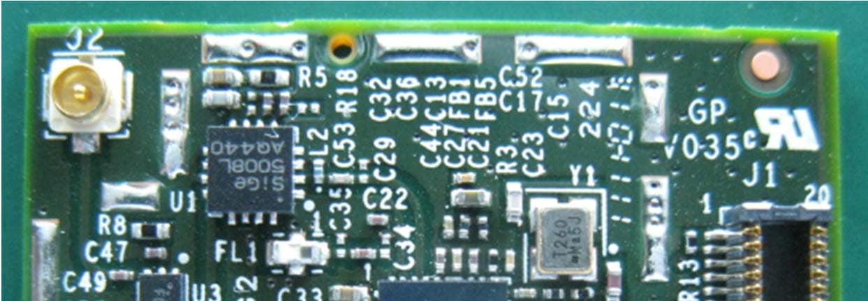
Click to zoom
Application Details
- Equipment Class
- DTS - Digital Transmission System
- Date of Grant
- Sep 01, 2011
- Application Purpose
- Original Equipment
- Date of Application
- Aug 31, 2011
- Equipment Note
- WIFI 11A/N MODULE
- Frequency Range
- 5755.00000000 - 5795.00000000
- Country
- Taiwan
Documents & Files
Document Text
Text extracted from the exhibit documents filed with the FCC. Open a document above to read the original.
Users Manual
Confidential 1 MIC-A2 WIFI Module User Manual Rev. 0.01 Confidential 2 Reviewers Department Name Review Dates Plan Results Director of Engineering Hardware Engineering Confidential 3 Table of Contents 1. INTRODUCTION .................................................................................................................................................. 4 1.1 SCOPE .............................................................................................................................................................. 4 1.2 FUNCTION ........................................................................................................................................................ 4 2. PRODUCT SPECIFICATION ............................................................................................................................... 5 2.1 ELECTRICAL SPECIFICATION ................................................................................................................................ 5 3. MECHANICAL DRAWING .................................................................................................................................. 6 4. REGULATORY INFORMATION ........................................................................................................................ 7 Confidential 4 1. Introduction Project Name: 802.11n WIFI module This documentation describes the product specification of the 802.11n WIFI module, it is a confidential document of FOXCONN. 1.1 Scope The MIC-A2 802.11n WIFI module provides wireless modem functionality utilizing OFDM technology. The objective of this use manual is to verify the functionality of the MIC-A2 802.11n WIFI module RF/Digital electronic design against the design specifications. This revision includes results taken at various temperatures (0°C,25°C,65 °C) and VDD voltages (3.1V,3.3V,5.25V), VDDIO Voltage (2.7V,2.8V,2.9V). Included are statements of test purpose, test methodologies, test modes and parameters, environmental conditions, applicable specifications, and typical reference design performance. The major specifications and documents are listed below and upon to update in the following new revisions. ● 802.11n: IEEE P802.11n/D2.07-Mar 2006 Paragraph 20.3.20.1 This device is operated in 5180~5240MHz (indoor only) and 5745~5825MHz. 1.2 Function Support IEEE 802.11n specified functions 1x1 single stream with antenna diversity SDIO V2.0 interface support Confidential 5 2. Product Specification 2.1 Electrical Specification Absolute Maximum Ratings These specifications indicate levels where permanent damage to the device can occur. Functional operation is not guaranteed under these conditions. Operation at absolute maximum conditions for extended can adversely affect long-term reliability of the device. Confidential 6 3. Mechanical Drawing Confidential 7 4. Regulatory Information USA-Federal Communications Commission (FCC) This device complies with Part 15 of the FCC Rules. Operation is subject to the following two conditions: (1) This device may not cause harmful interference, and (2) This device must accept any interference received, including interference that may cause undesired operation. Caution Any changes or modifications not expressly approved by the party responsible for compliance could void the user’s authority to operate the equipment. Labeling Hon Hai Precision 802.11n WIFI module MIC-A2 labeled as below. FCC ID: MCLMICA2 The proposed with FCC ID label format is to be placed on the module. If FCC ID is not visible when the module is installed into the system, “Contains FCC ID: MCLMICA2” shall be placed on the outside of final host system. Caution: Exposure to Radio Frequency Radiation. To comply with FCC RF exposure compliance requirements, a separation distance of at least 20 cm must be maintained between the antenna of this device and all persons. This device must not be co-located or operating in conjunction with any other antenna or transmitter. Canada-Industry Canada (IC) This device complies with RSS 210 of Industry Canada. Operation is subject to the following two conditions: (1) This device may not cause interference, and (2) This device must accept any interference, including interference that may cause undesired operation of this device. Labeling Hon Hai Precision 802.11n WIFI module MIC-A2 labeled as below. IC :2878D-MICA2 The proposed with IC No. label format is to be placed on the module. If IC No. is not visible when the module is installed into the system, “Contains IC :2878D-MICA2” shall be placed on the outside of final host Confidential 8 system. The term “IC” before the equipment certification number only signifies that the Industry Canada technical specifications were met. Caution: Exposure to Radio Frequency Radiation. To comply with IC RF exposure compliance requirements, a separation distance of at least 20 cm must be maintained between the antenna of this device and all persons. This device must not be co-located or operating in conjunction with any other antenna or transmitter.
Cover Letter(s)
Date: July 11, 2011 Federal Communications Commission 7435 Oakland Mills Road Columbia MD 21046 Subject: Request for Confidentiality FCC ID: MCLMICA2 To Whom It May Concern: Pursuant to the provisions of Sections 0.457 and 0.459 of the Commission’s rules (47 CFR §§ 0.457, 0.459), we are requesting the Commission to withhold the following attachments as confidential document from public disclosure indefinitely. Schematic Diagram Block Diagram Theory of Operation Antenna Specification Above mentioned document contains detailed system and equipment description are considered as proprietary information in operation of the equipment. The public disclosure of above documents might be harmful to our company and would give competitor an unfair advantage in the market. It is our understanding that all measurement test reports, FCC ID label format and correspondent during certification review process cannot be granted as confidential documents and those information will be available for public review once the grant of equipment authorization is issued. Best Regards, Rio Chen, Compliance Manager Hon Hai Precision Ind. Co., Ltd.
Cover Letter(s)
Applicant/Grantee Hon Hai Precision Ind. Co.,Ltd. FCC ID: MCLMICA2 Section 15.212 Modular Transmitters Request for Modular Approval Request for Limited Modular Approval Requirements EUT Conditions Comply (Y/N) Single Modular Approval Requirements 1 The radio elements of the modular transmitter must have their own shielding. The physical crystal and tuning capacitors may be located external to the shielded radio elements. The device is equipped with Metal shielding to cover RF section. Refer to external photos Y 2 The modular transmitter must have buffered modulation/data inputs (if such inputs are provided) to ensure that the module will comply with Part 15 requirements under conditions of excessive data rates or over- modulation. All inputs to the device are buffered through logic U2 inputs. Refer to Schematic Diagram. Y 3 The modular transmitter must have its own power supply regulation. The device is equipped with Internal 1.2V/1.4V/3.3VDC regulator. Refer to Schematics. Y 4 The modular transmitter must comply with the antenna and transmission system requirements of Sections 15.203, 15.204(b) and 15.204(c). The antenna must either be permanently attached or employ a “unique” antenna coupler (at all connections between the module and the antenna, including the cable). The “professional installation” provision of Section 15.203 is not applicable to modules but can apply to limited modular approvals under paragraph (b) of this section. Device is equipped with unique antenna (part number: 20279- 001E-01 (i-pex)and U.FL-R-SMT- 1(10)(Hirose) 1(10)(Hirose) Y 5 The modular transmitter must be tested in a stand-alone configuration, i.e., the module must not be inside another device during testing for compliance with Part 15 requirements. Unless the transmitter module will be battery powered, it must comply with the AC line conducted requirements found in Section 15.207. AC or DC power lines and data input/output lines connected to the module must not contain ferrites, unless they will be marketed with the module (see Section 15.27(a)). The length of these lines shall be the length typical of actual use or, if that length is unknown, at least 10 centimeters to insure that there is no coupling between the case of the module and supporting equipment. Any accessories, peripherals, or support equipment connected to the module during testing shall be unmodified and commercially available (see Section 15.31(i)). The device was tested outside of the Laptop PC for full modular approval. Refer to setup photos. Y 6 The modular transmitter must be equipped with either a permanently affixed label or must be capable of electronically displaying its FCC identification number. (A) If using a permanently affixed label, the modular transmitter must be labeled with its own FCC identification number, and, if the FCC identification number is not visible when the module is installed inside another device, then the outside of the device into which the module is installed must also display a label referring to the enclosed module. This exterior label can use wording such as the following: “Contains Transmitter Module FCC ID: XYZMODEL1” or “Contains FCC ID: XYZMODEL1.” Any similar wording that expresses the same meaning may be used. The Grantee may either provide such a label, an example of which must be included in the application for equipment authorization, or, must provide adequate instructions along with the module which explain this requirement. In the latter case, a copy of these instructions must be included in the application for equipment authorization. (B) If the modular transmitter uses an electronic display of the FCC identification number, the information must be readily accessible and visible on the modular transmitter or on the device in which it is installed. If the module is installed inside another device, then the outside of the device into which the module is installed must display a label referring to the enclosed module. This exterior label can use wording such as the following: “Contains FCC certified transmitter module(s).” Any similar wording that expresses the same meaning may be used. The user manual must include instructions on how to access the electronic display. A copy of these instructions must be included in the application for equipment authorization. The proposed FCC ID label format is to be placed on the module. If FCC ID is not visible when the module is installed into the system, “Contains FCC ID: MCLMICA2” shall be placed on the outside of final host system. Y 7 The modular transmitter must comply with any specific rules or operating requirements that ordinarily apply to a complete transmitter and the manufacturer must provide adequate instructions along with the module to explain any such requirements. A copy of these instructions must be included in the application for equipment authorization. Refer to “User’s Guide” Exhibit Y 8 The modular transmitter must comply with any applicable RF exposure requirements in its final configuration. The device complies with RF exposure compliance requirement Y A limited modular approval may be granted for single or split modular transmitters that do not comply with all of the above requirements, e.g., shielding, minimum signaling amplitude, buffered modulation/data inputs, or power supply regulation, if the manufacturer can demonstrate by alternative means in the application for equipment authorization that the modular transmitter meets all the applicable Part 15 requirements under the operating conditions in which the transmitter will be used. Limited modular approval also may be granted in those instances where compliance with RF exposure rules is demonstrated only for particular product configurations. The applicant for certification must state how control of the end product into which the module will be installed will be maintained such that full compliance of the end product is always ensured.
External Photos
Top view-Internal photo Top view-External Photo Bottom view
Internal Photos
Top view-Internal photo Top view-External Photo Bottom view
Test Report
FCC CFR47 PART 15 SUBPART C INDUSTRY CANADA RSS-210 ISSUE 8 CERTIFICATION TEST REPORT FOR WIFI 11A/N MODULE MODEL NUMBER: MIC-A2 FCC ID: MCLMICA2 IC: 2878D-MICA2 REPORT NUMBER: 11J13871-6 ISSUE DATE: July 14, 2011 Prepared for HON HAI PRECISION IND. CO., LTD. 5F-1, 5 HSIN-AN ROAD HSINCHU SCIENCE-BASED INDUSTRIAL PARK TAIWAN, R.O.C. Prepared by COMPLIANCE CERTIFICATION SERVICES (UL CCS) 47173 BENICIA STREET FREMONT, CA 94538, U.S.A. TEL: (510) 771-1000 FAX: (510) 661-0888 REPORT NO: 11J13871-6 DATE: July 14, 2011 FCC ID: MCLMICA2 IC: 2878D-MICA2 Page 2 of 100 COMPLIANCE CERTIFICATION SERVICES (UL CCS) FORM NO: CCSUP4701D 47173 BENICIA STREET, FREMONT, CA 94538, USA TEL: (510) 771-1000 FAX: (510) 661-0888 This report shall not be reproduced except in full, without the written approval of UL CCS. Revision History Rev. Issue Date Revisions Revised By -- 7/14/2011 Initial Issue T. Chan REPORT NO: 11J13871-6 DATE: July 14, 2011 FCC ID: MCLMICA2 IC: 2878D-MICA2 Page 3 of 100 COMPLIANCE CERTIFICATION SERVICES (UL CCS) FORM NO: CCSUP4701D 47173 BENICIA STREET, FREMONT, CA 94538, USA TEL: (510) 771-1000 FAX: (510) 661-0888 This report shall not be reproduced except in full, without the written approval of UL CCS. TABLE OF CONTENTS 1. ATTESTATION OF TEST RESULTS .................................................................................... 5 2. TEST METHODOLOGY ........................................................................................................ 6 3. FACILITIES AND ACCREDITATION .................................................................................... 6 4. CALIBRATION AND UNCERTAINTY .................................................................................. 6 4.1. MEASURING INSTRUMENT CALIBRATION ................................................................ 6 4.2. SAMPLE CALCULATION ............................................................................................... 6 4.3. MEASUREMENT UNCERTAINTY ................................................................................. 6 5. EQUIPMENT UNDER TEST ................................................................................................. 7 5.1. DESCRIPTION OF EUT ................................................................................................. 7 5.2. MAXIMUM OUTPUT POWER ........................................................................................ 7 5.3. DESCRIPTION OF AVAILABLE ANTENNAS ................................................................ 7 5.4. SOFTWARE AND FIRMWARE ...................................................................................... 7 5.5. WORST-CASE CONFIGURATION AND MODE ............................................................ 7 5.6. DESCRIPTION OF TEST SETUP .................................................................................. 8 6. TEST AND MEASUREMENT EQUIPMENT ....................................................................... 10 7. ANTENNA PORT TEST RESULTS .................................................................................... 11 7.1. 802.11a MODE IN THE 5.8 GHz BAND ....................................................................... 11 7.1.1. AVERAGE POWER .............................................................................................. 11 7.1.2. 6 dB BANDWIDTH ................................................................................................ 12 7.1.3. 99% BANDWIDTH ................................................................................................ 16 7.1.4. OUTPUT POWER ................................................................................................. 20 7.1.5. POWER SPECTRAL DENSITY ............................................................................ 24 7.1.6. CONDUCTED SPURIOUS EMISSIONS ............................................................... 28 7.2. 802.11n HT20 MODE IN THE 5.8 GHz BAND ............................................................. 35 7.2.1. AVERAGE POWER .............................................................................................. 35 7.2.2. 6 dB BANDWIDTH ................................................................................................ 36 7.2.3. 99% BANDWIDTH ................................................................................................ 40 7.2.4. OUTPUT POWER ................................................................................................. 44 7.2.5. POWER SPECTRAL DENSITY ............................................................................ 48 7.2.6. CONDUCTED SPURIOUS EMISSIONS ............................................................... 52 7.3. 802.11n HT40 MODE IN THE 5.8 GHz BAND ............................................................. 59 7.3.1. AVERAGE POWER .............................................................................................. 59 7.3.2. 6 dB BANDWIDTH ................................................................................................ 60 7.3.3. 99% BANDWIDTH ................................................................................................ 63 7.3.4. OUTPUT POWER ................................................................................................. 66 7.3.5. POWER SPECTRAL DENSITY ............................................................................ 69 7.3.6. CONDUCTED SPURIOUS EMISSIONS ............................................................... 72 8. RADIATED TEST RESULTS .............................................................................................. 77 REPORT NO: 11J13871-6 DATE: July 14, 2011 FCC ID: MCLMICA2 IC: 2878D-MICA2 Page 4 of 100 COMPLIANCE CERTIFICATION SERVICES (UL CCS) FORM NO: CCSUP4701D 47173 BENICIA STREET, FREMONT, CA 94538, USA TEL: (510) 771-1000 FAX: (510) 661-0888 This report shall not be reproduced except in full, without the written approval of UL CCS. 8.1. LIMITS AND PROCEDURE .............…
Text truncated - open the document above for the full version.
Test Setup Photos
REPORT NO: 11J13871-6 DATE: July 14, 2011 FCC ID: MCLMICA2 IC: 2878D-MICA2 Page 90 of 100 COMPLIANCE CERTIFICATION SERVICES (UL CCS) FORM NO: CCSUP4701D 47173 BENICIA STREET, FREMONT, CA 94538, USA TEL: (510) 771-1000 FAX: (510) 661-0888 This report shall not be reproduced except in full, without the written approval of UL CCS. 11. SETUP PHOTOS ANTENNA PORT CONDUCTED RF MEASUREMENT SETUP ANTENNA PORT CONDUCTED PHOTO REPORT NO: 11J13871-6 DATE: July 14, 2011 FCC ID: MCLMICA2 IC: 2878D-MICA2 Page 91 of 100 COMPLIANCE CERTIFICATION SERVICES (UL CCS) FORM NO: CCSUP4701D 47173 BENICIA STREET, FREMONT, CA 94538, USA TEL: (510) 771-1000 FAX: (510) 661-0888 This report shall not be reproduced except in full, without the written approval of UL CCS. RADIATED RF MEASUREMENT SETUP RADIATED FRONT PHOTO REPORT NO: 11J13871-6 DATE: July 14, 2011 FCC ID: MCLMICA2 IC: 2878D-MICA2 Page 92 of 100 COMPLIANCE CERTIFICATION SERVICES (UL CCS) FORM NO: CCSUP4701D 47173 BENICIA STREET, FREMONT, CA 94538, USA TEL: (510) 771-1000 FAX: (510) 661-0888 This report shall not be reproduced except in full, without the written approval of UL CCS. RADIATED BACK PHOTO REPORT NO: 11J13871-6 DATE: July 14, 2011 FCC ID: MCLMICA2 IC: 2878D-MICA2 Page 93 of 100 COMPLIANCE CERTIFICATION SERVICES (UL CCS) FORM NO: CCSUP4701D 47173 BENICIA STREET, FREMONT, CA 94538, USA TEL: (510) 771-1000 FAX: (510) 661-0888 This report shall not be reproduced except in full, without the written approval of UL CCS. RADIATED RF MEASUREMENT SETUP FOR PORTABLE CONFIGURATION WITH LONG CABLE ANTENNA X-AXIS FRONT PHOTO REPORT NO: 11J13871-6 DATE: July 14, 2011 FCC ID: MCLMICA2 IC: 2878D-MICA2 Page 94 of 100 COMPLIANCE CERTIFICATION SERVICES (UL CCS) FORM NO: CCSUP4701D 47173 BENICIA STREET, FREMONT, CA 94538, USA TEL: (510) 771-1000 FAX: (510) 661-0888 This report shall not be reproduced except in full, without the written approval of UL CCS. Y-AXIS FRONT PHOTO REPORT NO: 11J13871-6 DATE: July 14, 2011 FCC ID: MCLMICA2 IC: 2878D-MICA2 Page 95 of 100 COMPLIANCE CERTIFICATION SERVICES (UL CCS) FORM NO: CCSUP4701D 47173 BENICIA STREET, FREMONT, CA 94538, USA TEL: (510) 771-1000 FAX: (510) 661-0888 This report shall not be reproduced except in full, without the written approval of UL CCS. Z-AXIS FRONT PHOTO REPORT NO: 11J13871-6 DATE: July 14, 2011 FCC ID: MCLMICA2 IC: 2878D-MICA2 Page 96 of 100 COMPLIANCE CERTIFICATION SERVICES (UL CCS) FORM NO: CCSUP4701D 47173 BENICIA STREET, FREMONT, CA 94538, USA TEL: (510) 771-1000 FAX: (510) 661-0888 This report shall not be reproduced except in full, without the written approval of UL CCS. RADIATED RF MEASUREMENT SETUP FOR PORTABLE CONFIGURATION WITH SHORT CABLE ANTENNA X-AXIS FRONT PHOTO REPORT NO: 11J13871-6 DATE: July 14, 2011 FCC ID: MCLMICA2 IC: 2878D-MICA2 Page 97 of 100 COMPLIANCE CERTIFICATION SERVICES (UL CCS) FORM NO: CCSUP4701D 47173 BENICIA STREET, FREMONT, CA 94538, USA TEL: (510) 771-1000 FAX: (510) 661-0888 This report shall not be reproduced except in full, without the written approval of UL CCS. Y-AXIS FRONT PHOTO REPORT NO: 11J13871-6 DATE: July 14, 2011 FCC ID: MCLMICA2 IC: 2878D-MICA2 Page 98 of 100 COMPLIANCE CERTIFICATION SERVICES (UL CCS) FORM NO: CCSUP4701D 47173 BENICIA STREET, FREMONT, CA 94538, USA TEL: (510) 771-1000 FAX: (510) 661-0888 This report shall not be reproduced except in full, without the written approval of UL CCS. Z-AXIS FRONT PHOTO REPORT NO: 11J13871-6 DATE: July 14, 2011 FCC ID: MCLMICA2 IC: 2878D-MICA2 Page 99 of 100 COMPLIANCE CERTIFICATION SERVICES (UL CCS) FORM NO: CCSUP4701D 47173 BENICIA STREET, FREMONT, CA 94538, USA TEL: (510) 771-1000 FAX: (510) 661-0888 This report shall not be reproduced except in full, without the written approval of UL CCS. POWERLINE CONDUCTED EMISSIONS MEASUREMENT SETUP LINE CONDUCTED FRONT PHOTO REPORT NO: 11J13871-6 DATE: July 14, 2011 FCC ID: MCLMICA2 IC: 2878D-MICA2 Page 100 of 100 COMPLIANCE CERTIFICATION SERVICES (UL CCS) FORM NO: CCSUP4701D 47173 BENICIA STREET, FREMONT, CA 94538, USA TEL: (510) 771-1000 FAX: (510) 661-0888 This report shall not be reproduced except in full, without the written approval of UL CCS. END OF REPORT LINE CONDUCTED BACK PHOTO
Contact Information
Applicant
Mrs. Rio Chen(Compliance Deputy Manager)
Technical Contact
Compliance Certification ServicesThu Chan
[email protected]510-771-1000
47173 Benicia Street · Fremont · United States
Test Firm
Compliance Certification ServicesThu Chan
Technical Specifications
| # | Rule Parts | Frequency Range | Power Output |
|---|---|---|---|
| 2 | 15C | 5.75 GHz - 5.79 GHz | 44.00 mW |
Other Applications from HON HAI Precision Ind. Co., Ltd.

MCLT77W968
Jun 03, 2021LTE M.2 Module
Equipment Class
CBE - Citizens Band End User Devices
MCLT77W968C9
Feb 13, 2020LTE M.2 Module
Equipment Class
PCB - PCS Licensed Transmitter
MCLADB1761WF
Jun 03, 2015IP Set-Top Box with Wi-Fi 11ac
Equipment Class
DTS - Digital Transmission System
MCLADB1761W
Jun 02, 2015IP Set-Top Box
Equipment Class
DTS - Digital Transmission System
MCLT77H566
Feb 16, 2015WiFi/BT Module
Equipment Class
DTS - Digital Transmission System