MCLT60H418WLAN 802.11b Card
HON HAI Precision Ind. Co., Ltd.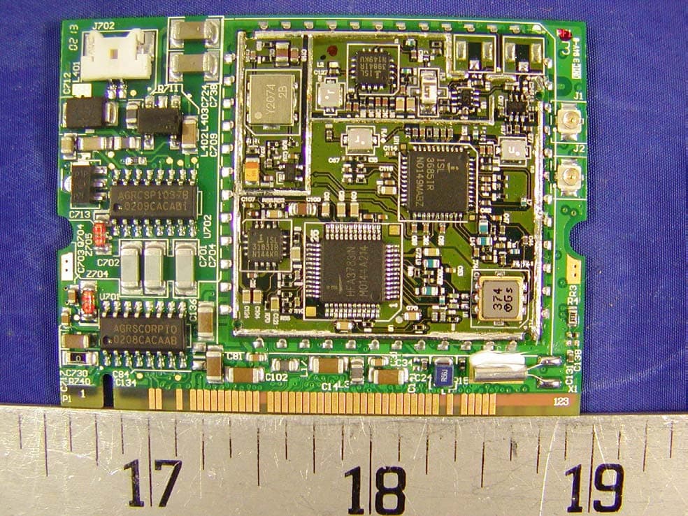
Click to zoom
Application Details
- Equipment Class
- DSS - Part 15 Spread Spectrum Transmitter
- Date of Grant
- May 29, 2002
- Application Purpose
- Original Equipment
- Date of Application
- May 29, 2002
- Equipment Note
- WLAN 802.11b Card
- Frequency Range
- 2413.50000000 - 2464.20000000
- Country
- Taiwan
Documents & Files
Document Text
Text extracted from the exhibit documents filed with the FCC. Open a document above to read the original.
Users Manual
i Notice for Users in the USA FCC Statement WARNING - FCC Regulations state that any unauthorized changes or modifications to this equipment not expressly approved by the manufacturer could void the user’s authority to operate this equipment. Note: This equipment has been tested and found to comply with the limits for a Class B digital device pursuant to Part 15 of the FCC Rules. These limits are designed to provide reasonable protection against harmful interference in a residential installation. This equipment generates, uses and can radiate radio frequency energy and, if not installed and used in accordance with the instructions, may cause harmful interference to radio communications. However, there is no guarantee that interference will not occur in a particular installation. If this equipment does cause harmful interference to radio or television reception, which can be determined by turning the equipment off and on, the user is encouraged to try to correct the interference by one or more of the following measures: • Reorient or relocate the receiving antenna. • Increase the distance between the equipment and receiver. • Connect the equipment into an outlet on a circuit different from that to which the receiver is connected. • Consult the dealer or an experienced radio/TV technician for help. A shielded I/F cable and included ferrite core for LAN cable is required to insure compliance with FCC regulation for Class B computing equipment. *AsanENERGYSTAR ® Partner, SHARP has determined that this product meets the ENERGY STAR ® guidelines for energy efficiency. Declaration of Conformity SHARP PERSONAL COMPUTER, PC-MV Series This device complies with part 15 of the FCC rules. Operation is subject to the following conditions:(1) this device may not cause harmful interference, and (2) this device must accept any interference received, including interference that may cause undesired operation. Responsible Party: SHARP ELECTRONICS CORPORATION Sharp Plaza, Mahwah, New Jersey 07430-2135 TEL: 1-800-BE-SHARP ii About the Modem This equipment complies with Part 68 of FCC rules. On the bottom of this equipment is a label that contains, among other information, the FCC registration number and ringer equivalence number (REN) for this equipment. If requested, this information must be provided to the telephone company. The modem jack of this equipment complies with Sub-part F of Part 68 of FCC rules. The REN is used to determine the quantity of devices which may be connected to the telephone line. Excessive RENs on the telephone line may result in the devices not ringing in response to an incoming call. In most, but not all areas, the sum of the RENs should not exceed five (5.0). To be certain of the number of devices that may be connected to the line, as determined by the total RENs contact the telephone company to determine the maximum REN for the calling areas. If the terminal equipment causes harm to the telephone network, the telephone company will notify you in advance that temporary discontinuance of service may be required. But if advance notice isn't practical, the telephone company will notify the customer as soon as possible. Also, you will be advised of your right to file a complaint with the FCC if you believe it necessary. The telephone company may make changes in its facilities, equipment, operations, or procedures that could affect the operation of the equipment. If this happens, the telephone company will provide advance notice in order for you to make the necessary modifications in order to maintain uninterrupted service. If trouble is experienced with this equipment, please contact Sharp Electronics Corp. for repair and (or) warranty information (Refer to the end of this section). If the trouble is causing harm to the telephone network, the telephone company may request you remove the equipment from the network until the problem is resolved. The equipment cannot be used on public coin service provided by the telephone company. Connection to Party Line Service is subject to state tariffs. (Contact the state public utility commission, public service commission or corporation commission for information.) iii The Telephone Consumer Protection Act of 1991 makes it unlawful for any person to use a computer or other electronic device, including fax machines, to send any message unless such message clearly contains in a margin at the top or bottom of each transmitted page or on the first page of the transmission, the date and time it is sent and an identification of the business or other entity, or other individual sending the message and the telephone number of the sending machine or such business, other entity, or individual. (The telephone number provided may not be a 900 number or any other number for which charges exceed local or long-distance transmission charges.) To program this information, refer to the manual of the communication software. For Wireless LAN Bundled Model Wireless LAN / Modem Model Name:T60H418 FCC ID:MCLT60H418 This device complies with part 15 of the FCC rules. Operation is subject to the following conditions: (1) this device may not cause harmful interference, and (2) this device must accept any interference received, including interference that may cause undesired operation. Warning This product utilizes tin-lead solder, and fluorescent lamp containing a small amount of mercury. Disposal of these materials may be regulated due to environmental considerations. For disposal or recycling information, please contact your local authorities or the Electronics Industries Alliance:www.eiae.org Copyright It is the intent of Sharp that this product be used in full compliance with the copyright laws of the United States and that prior permission be obtained from copyright owners whenever necessary. Product Information and Customer Assistance For Product Information and Customer Assistance: Call:1-800-BE-SHARP (237-4277) Sharp Systems of America 5901 Bolsa Avenue, Huntingto…
Text truncated - open the document above for the full version.
Cover Letter(s)
AMBIT Microsystems Corporation 5F-1, 5 Hsin-An Road, Hsinchu Science-Based Industrial Park, Taiwan TEL:+886-3-5784975 FAX:+886-3-5775100 Taipei Branch: 4, Ming Shen Street Tu Chen Industrial District, Tu Chen Taipei Hsien 236, Taiwan, R.O.C. TEL:+886-2-2268-6141 FAX:+886-2-2268-6001 Federal Communications Commission Authorization and Evaluation Division Confidentiality Request regarding application for certification of FCC ID: MCLT60H418 Pursuant to Sections 0.457 and 0.459 of the Commission’s Rules, we hereby request confidential treatment of information accompanying this application as outlined below: Schematics BOM Block Diagram Layout The above materials contain trade secrets and proprietary information not customarily released to the public. The public disclosure of these materials may be harmful to the applicant and provide unjustified benefits to its competitors. The applicant understands that pursuant to Section 0.457 of the Rules, disclosure of this application and all accompanying documentation will not be made before the date of the Grant for this application. Sincerely, Roger Wu / Director, Data Communication R&D Department
External Photos
APPENDIX C - EUT PHOTOGRAPHS Component View Solder View Transmitter View B24-18 Antenna Overall View B24-19 Antenna Overall View
ID Label/Location Info
APPENDIX A - FCC ID LABEL INFORMATION Proposed FCC ID Label Proposed Label Location on EUT Solder Side of EUT/FCC ID Label
Internal Photos
APPENDIX C - EUT PHOTOGRAPHS Component View Solder View Transmitter View B24-18 Antenna Overall View B24-19 Antenna Overall View
Operational Description
COMPANY CONFIDENTIAL REV.0.1 10/30/200211 1 T60H418.00 MRS.doc T60H418.00 MINIPCI IIIB Wireless LAN/Modem Combo Card Marketing Requirements Specification January 28, 2002 COMPANY CONFIDENTIAL REV.0.1 10/30/200211 2 T60H418.00 MRS.doc 0. REVISION HISTORY ............................................................................................................................................. 3 1. INTRODUCTION .................................................................................................................................................... 4 1.1 S COPE................................................................................................................................................................... 4 1.2 W IRELESS LAN FUNCTION.................................................................................................................................. 4 1.3 M ODEM FUNCTION............................................................................................................................................... 4 2. PRODUCT REQUIREMENTS............................................................................................................................... 6 2.1 G ENERAL ELECTRICAL SPECIFICATIONS............................................................................................................... 6 2.2 H ARDWARE ARCHITECTURE................................................................................................................................. 7 2.3 M ECHANICAL REQUIREMENTS.............................................................................................................................. 7 2.4 A NTENNA CONNECTION....................................................................................................................................... 8 2.5 R EFERENCE OSCILLATOR..................................................................................................................................... 8 3. RELIABILITY, MAINTAINABILITY AND QUALITY ....................................................................................8 3.1 R ELIABILITY......................................................................................................................................................... 8 3.2 M AINTAINABILITY................................................................................................................................................ 8 3.3 Q UALITY............................................................................................................................................................... 8 4. ENVIRONMENTAL REQUIREMENTS .............................................................................................................. 8 4.1 T EMPERATURE...................................................................................................................................................... 8 4.1.1 Operating Temperature Conditions ............................................................................................................. 8 4.1.2 Non-Operating Temperature Conditions ..................................................................................................... 8 4.2 H UMIDITY............................................................................................................................................................. 8 4.2.1 Operating Humidity Conditions................................................................................................................... 8 4.2.2 Non-Operating Humidity conditions............................................................................................................ 9 COMPANY CONFIDENTIAL REV.0.1 10/30/200211 3 T60H418.00 MRS.doc 0. Revision History Date: June 11, 2001 REV.0.1 Date: June 22, 2001 REV.0.2 Date: January 28, 2002 REV. 1.0 Change 1.2 Driver Support Change 2,1 Transmitter Output Power Receiver Sensitivity Change 2.3 Mechanical Requirement Change 2.5 Antenna Connection Change 4.1.1 Operating Temperature COMPANY CONFIDENTIAL REV.0.1 10/30/200211 4 T60H418.00 MRS.doc 1. Introduction Project Name : MINIPCI 3B Wireless LAN/ Lucent Scorpio Modem Combo Project Code : T60H418.00 This documentation describes the marketing requirements specification of the Ambit MINIPCI 3B Wireless LAN/Modem Combo card based on Intersil’s Prism 2.5 chipsets. It is a confidential document of AMBIT. 1.1 Scope AMBIT MINIPCI 3B WLAN/Modem complied with IEEE 802.11b 11Mbps Standard. The WLAN/Modem application is implemented. This RF combo card is developed for Wireless LAN application complied with IEEE 802.11b 11Mbps standard in ISM band. It can be used to provide a variety of low-cost wireless network interfaces to build your wireless connection via simply SMT procedure to speed the time to market. Three Intersil’s chips are implemented including ISL3984, ISL3685, HFA3783. With V.90 technology, the modem part can achieve internet connection rates up to 56 kbits/s with backward compatibility. The Audio CODEC will be placed on the notebook and contact with Modem Codec by AC-Link Interface. The combo card complies with MINIPCI 3B form factor. 1.2 Wireless LAN Function z Compatible with IEEE 802.11b high rate standard to provide wireless Ethernet speeds of 11Mbps data rate z Dynamic data rate switching with 11, 5.5, 2 and 1Mbps z Allows auto fallback data rate for optimized reliability, throughput and transmission range z Supports wireless data encryption with 64/128-bit WEP standard for security z Dual diversity antenna connectors supported for the multi-path environment z Drivers supports Windows 98SE, ME, 2000, XP 1.3 Modem Function z ITU-T V.90 data rates with auto-fallback to V.34, V.32terbo, V.32bis and fallbacks z TIA/EIA 602 standard for AT Command set z Supports V.42 error correction and V.42bis/MNP5 data compression z FAX capabilities: ITU-T V.17, V.29, V.27ter, V.21 Ch2 and TIA/EIA 578 Class1 FAX z …
Text truncated - open the document above for the full version.
Test Report
Note: This test report is specially limited to the above client company and the product model only. It may not be duplicated without prior written consent of Bay Area Compliance Laboratory Corporation. This report must not be used by the client to claim product endorsement by NVLAP or any agency of the U.S. Government. FCC 15 SUBPART C EMI MEASUREMENT AND TEST REPORT For AMBIT Microsystems Corporation 4-1, Ming Shen Street, Tu Chen Industrial District. Tu Chen, Taipei Hsien 236, Taiwan, R.O.C. FCC ID: MCLT60H418 May 29, 2002 This Report Concerns: Original Report Equipment Type: WLAN 802.11b Module Test Engineer: Jeff Lee Test Date: May 18, 2002 Reviewed By: Benjamin Jin Prepared By: Bay Area Compliance Laboratory Corporation 230 Commercial Street Sunnyvale, CA 94085 Tel: (408) 732-9162 Fax: (408) 732 9164 AMBIT Microsystems Corporation FCC ID: MCLT60H418 Report # R0205069_Rpt FCC 15.247 Test Report Page 2 of 29 TABLE OF CONTENTS 1 - GENERAL INFORMATION..................................................................................................................................4 1.1 PRODUCT DESCRIPTION FOR EQUIPMENT UNDER TEST (EUT) ..............................................................................4 1.2 OBJECTIVE.............................................................................................................................................................4 1.3 RELATED SUBMITTAL(S)/GRANT(S).......................................................................................................................4 1.4 TEST METHODOLOGY............................................................................................................................................4 1.5 TEST FACILITY.......................................................................................................................................................4 1.6 TEST EQUIPMENT LIST AND DETAILS.....................................................................................................................5 1.7 HOST SYSTEM CONFIGURATION LIST AND DETAILS..............................................................................................5 1.8 LOCAL SUPPORT EQUIPMENT LIST AND DETAILS...................................................................................................6 1.9 EXTERNAL I/O CABLING LIST AND DETAILS.........................................................................................................6 2 - SYSTEM TEST CONFIGURATION.....................................................................................................................7 2.1 JUSTIFICATION.......................................................................................................................................................7 2.2 EUT EXERCISE SOFTWARE....................................................................................................................................7 2.3 SPECIAL ACCESSORIES...........................................................................................................................................7 2.4 SCHEMATICS / BLOCK DIAGRAM...........................................................................................................................7 2.5 EQUIPMENT MODIFICATIONS.................................................................................................................................7 2.6 CONFIGURATION OF TEST SYSTEM.........................................................................................................................8 2.7 TEST SETUP BLOCK DIAGRAM...............................................................................................................................8 3 - SUMMARY OF TEST RESULTS..........................................................................................................................9 4 - PEAK OUTPUT POWER MEASUREMENT ....................................................................................................10 4.1 STANDARD APPLICABLE......................................................................................................................................10 4.2 MEASUREMENT PROCEDURE................................................................................................................................10 4.3 MEASUREMENT RESULT......................................................................................................................................10 5 - SPURIOUS EMISSION.........................................................................................................................................15 5.1 STANDARD APPLICABLE......................................................................................................................................15 5.2 MEASUREMENT PROCEDURE................................................................................................................................15 5.3 MEASUREMENT DATA..........................................................................................................................................15 6 - PEAK POWER SPECTRAL DENSITY ..............................................................................................................16 6.1 STANDARD APPLICABLE......................................................................................................................................16 6.2 MEASUREMENT PROCEDURE................................................................................................................................16 6.3 TEST RESULTS.....................................................................................................................................................16 7 - 6 DB BANDWIDTH...............................................................................................................................................17 7.1 STANDARD APPLICABLE.....................................…
Text truncated - open the document above for the full version.
Test Report
AMBIT Microsystems Corporation FCC ID: MCLT60H418 Report # R0205069_Rpt FCC 15.247 Test Report Page 16 of 29 6 - PEAK POWER SPECTRAL DENSITY 6.1 Standard Applicable According to §15.247 (d), for direct sequence systems, the peak power spectral density conducted from the intentional radiator to the antenna shall not be greater than 8 dBm in any 3 kHz band during any time interval of continuous transmission. 6.2 Measurement Procedure 1. Check the calibration of the measuring instrument using either an internal calibrator or a known signal from an external generator. 2. Position the EUT was set without connection to measurement instrument. Turn on the EUT and connect its antenna terminal to measurement instrument via a low loss cable. Then set it to any one measured frequency within its operating range, and make sure the instrument is operated in its linear range. 3. Adjust the center frequency of SA on any frequency be measured and set SA to zero span mode. And then, set RBW and VBW of spectrum analyzer to proper value. 4. Repeat above procedures until all frequencies measured were complete. 6.3 Test Results Please refer to the attached plot(s). AMBIT Microsystems Corporation FCC ID: MCLT60H418 Report # R0205069_Rpt FCC 15.247 Test Report Page 17 of 29 7 - 6 DB BANDWIDTH 7.1 Standard Applicable According to §15.247(a)(2), for direct sequence systems, the minimum 6dB bandwidth shall be at least 500 kHz. 7.2 Measurement Procedure 1. Check the calibration of the measuring instrument using either an internal calibrator or a known signal from an external generator. 2. Position the EUT without connection to measurement instrument. Turn on the EUT and connect it to measurement instrument. Then set it to any one convenient frequency within its operating range. Set a reference level on the measuring instrument equal to the highest peak value. 3. Measure the frequency difference of two frequencies that were attenuated 20 dB from the reference level. Record the frequency difference as the emission bandwidth. 4. Repeat above procedures until all frequencies measured were complete. 7.3 Measurement Data Please refer to appending plot for more information. AMBIT Microsystems Corporation FCC ID: MCLT60H418 Report # R0205069_Rpt FCC 15.247 Test Report Page 18 of 29 8 -100 KHZ BANDWIDTH OF BAND EDGES MEASUREMENT 8.1 Standard Applicable According to §15.247(c), in any 100 kHz bandwidth outside the frequency bands in which the spread spectrum intentional radiator is operating, the radio frequency power that is produced by the intentional radiator shall be at least 20 dB below that in the 100 kHz bandwidth within the band that contains the highest level of the desired power, based on either an RF conducted or a radiated measurement. In addition, radiated emissions which fall in the restricted bands, as defined in §15.205(a), must also comply with the radiated emission limits specified in §15.209(a) see §15.2057(c)). 8.2 Measurement Procedure 1. Check the calibration of the measuring instrument using either an internal calibrator or a known signal from an external generator. 2. Position the EUT without connection to measurement instrument. Turn on the EUT and connect its antenna terminal to measurement instrument via a low loss cable. Then set it to any one measured frequency within its operating range, and make sure the instrument is operated in its linear range. 3. Set both RBW and VBW of spectrum analyzer to 300 kHz with a convenient frequency span including 100kHz bandwidth from band edge. 4. Measure the highest amplitude appearing on spectral display and set it as a reference level. Plot the graph with marking the highest point and edge frequency. 5. Repeat above procedures until all measured frequencies were complete. 8.3 Test Results Please refer to the appending plot for more information.
Test Report
AMBIT Microsystems Corporation FCC ID: MCLT60H418 Report # R0205069_Rpt FCC 15.247 Test Report Page 19 of 29 9 - ANTENNA REQUIREMENT 9.1 Standard Applicable For intentional device, according to § 15.203, an intentional radiator shall be designed to ensure that no antenna other than that furnished by the responsible party shall be used with the device. And according to § 15.247 (1), if transmitting antennas of directional gain greater than 6 dBi are used the power shall be reduced by the amount in dB that the directional gain of the antenna exceeds 6 dBi. 9.2 Antenna Connected Construction The directional gain of antenna used for transmitting is 2 dBi, and the antenna connector is designed with permanent attachment and no consideration of replacement. Please see EUT photo for details. Please refer to the attachment for antenna details. B24-18 Antenna Left Side B24-18 Antenna Right Side シャープ株式会社 殿 形 式 :内蔵縦型タイプ 用 途 :PC用無線LAN 使用周波数 :2.4~2.5GHz 共振周波数 : 【測定項目】 最終筐体における左右アンテナ利得の測定 【データ】 PAGE 2 利得データ ......... 垂直面前後パターン 3 4 5 承 認 検 認 担 当 測定方向表示図 測 定 内 容 等 清 藤 三省電機株式会社 技術部 〒142-0063 東京都品川区荏原5丁目11番13号 TEL 03-3784-5103 FAX 03-5749-7270 〃 ......... 垂直面左右パターン 〃 ......... 水平面パターン 2002年5月7日 アンテナ指向特性・利得データ アンテナ指向特性/利得 2002年5月2日 0 ゚ 90 ゚ 180 ゚ 270 ゚ 0 -10 -20 -30dB アンテナ名称 : 左側(B24-019B0) 水平偏波 測定周波数 : 2450 MHz 標準アンテナレベル: -54.8 dBm アンテナ利得 : -5.9 dBd 平 均 利 得 : -8.7 dBd FILE NAME = 垂直面 前/後 パターン (Z-X PLANE) 0 ゚ 90 ゚ 180 ゚ 270 ゚ 0 -10 -20 -30dB アンテナ名称 : 右側(B24-019A0) 水平偏波 測定周波数 : 2450 MHz 標準アンテナレベル: -54.8 dBm アンテナ利得 : -5.4 dBd 平 均 利 得 : -9.8 dBd FILE NAME = 垂直面 前/後 パターン (Z-X PLANE) 0 ゚ 90 ゚ 180 ゚ 270 ゚ 0 -10 -20 -30dB アンテナ名称 : 左側(B24-019B0) 垂直偏波 測定周波数 : 2450 MHz 標準アンテナレベル: -54.8 dBm アンテナ利得 : -4.1 dBd 平 均 利 得 : -9.5 dBd FILE NAME = 垂直面 前/後 パターン (Z-X PLANE) 0 ゚ 90 ゚ 180 ゚ 270 ゚ 0 -10 -20 -30dB アンテナ名称 : 右側(B24-019A0) 垂直偏波 測定周波数 : 2450 MHz 標準アンテナレベル: -54.8 dBm アンテナ利得 : -5.3 dBd 平 均 利 得 : -10.6 dBd FILE NAME = 垂直面 前/後 パターン (Z-X PLANE) アンテナ指向特性/利得 2002年5月2日 0 ゚ 90 ゚ 180 ゚ 270 ゚ 0 -10 -20 -30dB アンテナ名称 : 左側(B24-019B0) 水平偏波 測定周波数 : 2450 MHz 標準アンテナレベル: -54.8 dBm アンテナ利得 : -2.1 dBd 平 均 利 得 : -8.5 dBd FILE NAME = 垂直面 左/右 パターン (Z-Y PLANE) 0 ゚ 90 ゚ 180 ゚ 270 ゚ 0 -10 -20 -30dB アンテナ名称 : 右側(B24-019A0) 水平偏波 測定周波数 : 2450 MHz 標準アンテナレベル: -54.8 dBm アンテナ利得 : -3.1 dBd 平 均 利 得 : -9.2 dBd FILE NAME = 垂直面 左/右 パターン (Z-Y PLANE) 0 ゚ 90 ゚ 180 ゚ 270 ゚ 0 -10 -20 -30dB アンテナ名称 : 左側(B24-019B0) 垂直偏波 測定周波数 : 2450 MHz 標準アンテナレベル: -54.8 dBm アンテナ利得 : -6.2 dBd 平 均 利 得 : -13.6 dBd FILE NAME = 垂直面 左/右 パターン (Z-Y PLANE) 0 ゚ 90 ゚ 180 ゚ 270 ゚ 0 -10 -20 -30dB アンテナ名称 : 右側(B24-019A0) 垂直偏波 測定周波数 : 2450 MHz 標準アンテナレベル: -54.8 dBm アンテナ利得 : -8.0 dBd 平 均 利 得 : -14.5 dBd FILE NAME = 垂直面 左/右 パターン (Z-Y PLANE) アンテナ指向特性/利得 2002年5月2日 0 ゚ 90 ゚ 180 ゚ 270 ゚ 0 -10 -20 -30dB アンテナ名称 : 左側(B24-019B0) 水平偏波 測定周波数 : 2450 MHz 標準アンテナレベル: -54.8 dBm アンテナ利得 : -4.0 dBd 平 均 利 得 : -9.9 dBd FILE NAME = 水 平 面 パターン (X-Y PLANE) 0 ゚ 90 ゚ 180 ゚ 270 ゚ 0 -10 -20 -30dB アンテナ名称 : 右側(B24-019A0) 水平偏波 測定周波数 : 2450 MHz 標準アンテナレベル: -54.8 dBm アンテナ利得 : -5.6 dBd 平 均 利 得 : -10.6 dBd FILE NAME = 水 平 面 パターン (X-Y PLANE) 0 ゚ 90 ゚ 180 ゚ 270 ゚ 0 -10 -20 -30dB アンテナ名称 : 左側(B24-019B0) 垂直偏波 測定周波数 : 2450 MHz 標準アンテナレベル: -54.8 dBm アンテナ利得 : -9.0 dBd 平 均 利 得 : -13.0 dBd FILE NAME = 水 平 面 パターン (X-Y PLANE) 0 ゚ 90 ゚ 180 ゚ 270 ゚ 0 -10 -20 -30dB アンテナ名称 : 右側(B24-019A0) 垂直偏波 測定周波数 : 2450 MHz 標準アンテナレベル: -54.8 dBm アンテナ利得 : -8.9 dBd 平 均 利 得 : -14.0 dBd FILE NAME = 水 平 面 パターン (X-Y PLANE) AMBIT Microsystems Corporation FCC ID: MCLT60H418 Report # R0205069_Rpt FCC 15.247 Test Report Page 20 of 29 10 - RF EXPOSURE According to §15.247(b)(4) and §1.1307(b)(1), systems operating under the provisions of this section shall be operated in a manner that ensures that the public is not exposed to radio frequency energy level in excess of the Commission’s guidelines. According to §1.1310 and §2.1093 RF exposure is calculated. Limits for Maximum Permissive Exposure (MPE) Frequency Range (MHz) Electric Field Strength (V/m) Magnetic Field Strength (A/m) Power Density (mW/cm 2 ) Averaging Time (minute) Limits for General Population/Uncontrolled Exposure 0.3-1.34 614 1.63 *(100) 30 1.34-30 824/f 2.19/f *(180/f 2 ) 30 30-300 27.5 0.073 0.2 30 300-1500 / / f/1500 30 1500-15000 / / 1.0 30 f = frequency in MHz * = Plane-wave equivalent power density MPE Prediction Predication of MPE limit at a given distance Equation from page 18 of OET Bulletin 65, Edition 97-01 S = PG/4πR² Where: S = power density P = power input to antenna G = power gain of the antenna in the direction of interest relative to an isotropic radiator R = distance to the center of radiation of the antenna Maximum peak output power at antenna input terminal: 8.20 (dBm ) Maximum peak output power at antenna input terminal: 6.61 (mW) Antenna Gain (typical): 2 (dBi) Maximum antenna gain: 1.58 (numeric) Prediction distance: 3 (cm) Predication frequency: 2400 (MHz) MPE limit for uncontrolled exposure at prediction frequency: 1 (mW/cm^2) Power density at predication frequency: 0.092 (mW/cm^2) Maximum allowable antenna gain: 17.11 (numeric) Maximum allowable antenna gain: 12.33 (dBi) Test Result The predicted power density level at 3 cm is 0.092mW/cm². This is below the uncontrolled exposure limit of 1mW/cm² at 2400 MHz. This radio is intended to be installed in laptop PC only and is thus classed as mobile equipment. AMBIT Microsystems Corporation FCC ID: MCLT60H418 Report # R0205069_Rpt FCC 15.247 Test Report Page 21 of 29 11 - SPURIOUS RADIATED EMISSION DATA 11.1 Measurement Uncertainty All measurements involve certain levels of uncertainties, especially in field of EMC. The factors contributing to uncertainties are spectrum analyzer, cable loss, antenna factor calibration, antenna directivity, antenna factor variation with height, antenna phase center variation, antenna factor frequency interpolation, measurement distance variation, site imperfections, mismatch (average), and system repeatability. Based on NIS 81, The Treatment of Uncertainty in EMC Measurements, the best estimate of the…
Text truncated - open the document above for the full version.
Test Setup Photos
APPENDIX B - TEST SETUP PHOTOGRAPHS Conducted Emission - Front View Conducted Emission - Rear View Radiated Emission - Front View Radiated Emission - Rear View
Contact Information
Applicant
Mrs. Rio Chen(Compliance Deputy Manager)
Test Firm
Bay Area Compliance LaboratoryJohn Chan
Technical Specifications
| # | Rule Parts | Frequency Range | Power Output |
|---|---|---|---|
| 1 | 15C | 2.41 GHz - 2.46 GHz | 7.00 mW |
Other Applications from HON HAI Precision Ind. Co., Ltd.

MCLT77W968
Jun 03, 2021LTE M.2 Module
Equipment Class
CBE - Citizens Band End User Devices
MCLT77W968C9
Feb 13, 2020LTE M.2 Module
Equipment Class
PCB - PCS Licensed Transmitter
MCLADB1761WF
Jun 03, 2015IP Set-Top Box with Wi-Fi 11ac
Equipment Class
DTS - Digital Transmission System
MCLADB1761W
Jun 02, 2015IP Set-Top Box
Equipment Class
DTS - Digital Transmission System
MCLT77H566
Feb 16, 2015WiFi/BT Module
Equipment Class
DTS - Digital Transmission System