MCLT60H424WLAN MiniPCI Type III
HON HAI Precision Ind. Co., Ltd.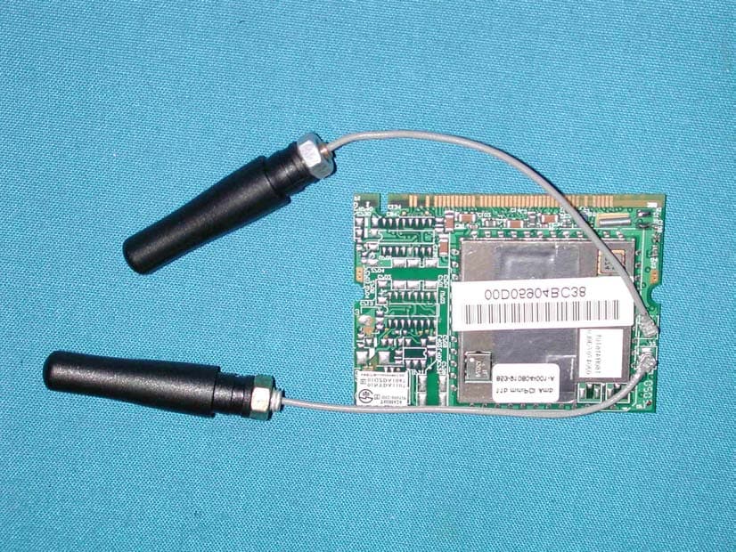
Click to zoom
Application Details
- Equipment Class
- DSS - Part 15 Spread Spectrum Transmitter
- Date of Grant
- Apr 29, 2002
- Application Purpose
- Original Equipment
- Date of Application
- Apr 29, 2002
- Equipment Note
- WLAN MiniPCI Type III
- Frequency Range
- 2412.00000000 - 2462.00000000
- Country
- Taiwan
Documents & Files
Document Text
Text extracted from the exhibit documents filed with the FCC. Open a document above to read the original.
Users Manual
Contents Chapter 1 About the T60H424 MiniPCI Card 1-1 Features 1-2 Applications 1-3 Product Kit Chapter 2 Network Configuration and Planning 2-1 Network Topology 2-2 Roaming Chapter 3 Adapter Installation and Configuration – Windows ® 98 / NT / 2000 3-1 System Requirements 3-2 Inserting the Adapter 3-3.1 T60H424 Driver Installation - Windows ® 98 3-3.2 Adapter Configuration - Windows ® 98 3-3.3 Protocol Installation - Windows ® 98 3-4 T60H424 Setup for Windows ® 2000 Chapter 4 Installing and Navigating the PRISM Configuration Utility 4-1 LAN-Express Configuration Utility - Installation 4-2 LAN-Express Configuration Utility - Navigation Appendix A Troubleshooting Appendix B Glossary Chapter 1 About the T60H424 MiniPCI Card The IEEE 802.11 T60H424 MiniPCI Card is compatible with any standard, notebook computer Type II or Type III PCMCIA slot / Type III MiniPCI slot. As a Plug-and-Play device, Windows 95/98/2000 will automatically recognize the T60L198 PCMCIA and initiate the installation process. Upon successful installation, the T60H424 MiniPCI card will communicate seamlessly with other T60H424 wireless home and office networking products. 1-1 FEATURES 1. Supports up to 11 Mbps data rate: T-1 line alternative/replacement that dramatically cuts costs. 2. Working range up to 800 ft. in an open environment enhances mobility. 3. Supports point-to-point and point-to-multipoint access provides increased flexibility. 4. Seamless connectivity to wired Ethernet and PC network LAN’s offers quick, trouble-free integration with existing networks. 5. Robust Direct Sequence Spread Spectrum (DSSS) technology provides secure, interference-resistant wireless connection. 6. Wireless connections eliminate the hassle and cost of cabling. 7. Supports a wide range of LAN (Local Area Network) Network Operating Systems (NOS) including Windows ® 98 and Windows ® 2000 8. Easy Plug and Play installation(T60L198). 9. Omni - directional antenna included 10. Greater flexibility to locate or move networked PC’s 1-2 APPLICATIONS T60H424 products offer a fast, reliable, cost-effective solution for wireless client access to the network the following applications and environments: Remote access to corporate network information E-mail, file transfer and terminal emulation Difficult-to-wire environments Historic or older buildings Buildings with asbestos insulation Open areas where wiring is difficult to employ Frequently changing environments Retailers, manufacturers or other organizations that frequently rearrange the workplace or relocate Temporary LANs for special projects or peak time usage Trade shows, exhibitions and construction sites that employ temporary networks. Retailers, airline and shipping companies that need additional workstations for a peak period and Auditors that require workgroups at customer sites. Access to database for mobile workers Medical, Technical and Retail specialists that require roaming access to a database or other network resources. SOHO (Small Office and Home Office) users Perfect for users that need a small, easy-to-install network that deploys rapidly. Inter-building connection Wireless building-to-building networks are quickly and easily installed, require no monthlylease fees, and provide the flexibility to reconfigure easily. 1-3 PRODUCT KIT The T60H424 product kit includes the following items. Ensure that the items in the following list have been included. If any of the listed items are missing, please contact your local dealer. 1 X T60L198 PCMCIA Type II Adapter or Type III T60H424 MiniPCI Adapter 1 X Driver 1 X User Manual & Utility Chapter 2 Network Configuring and Planning The T60H424 supports legacy Ethernet LAN network configuration options as defined by the IEEE 802.11 standards committee. The T60H424 can be configured as: . Ad-Hoc for departmental or SOHO LANs. . Infrastucture for enterprise LANs. . LAN-Interconnection for to point-to-point link as a campus backbone. 2-1 Network Topology Ad-Hoc Wireless LAN Notebook with T60L198/T60L244 Notebook with T60L198/T60L244 Desktop PC with T60L198/T60L244 Desktop PC with T60L198/T60L244 Fig.1 Ad-Hoc Wireless LAN An Ad-Hoc wireless LAN is a group of computers. Each equipped with on T60H424 adapter, connected as an independent wireless LAN.Computers in a specific Ad-Hoc wireless LAN must be configured to share the same radio channel. Ad-Hoc wireless LAN configurations are appropriate for branch level departments or SOHO operations. ㆚太網路 File Server Desktop PC Desktop PC Desktop PC with T60L198/T60L244 Desktop PC with T60L198/T60L244 Access PointAccess Point Notebook with T60L198/T60L244 Notebook with T60L198/T60L244 Fig.2 Infrastructure Wireless LAN Configuration Desktop PC with T60L198/T60L244 Desktop PC with T60L198/T60L244 The T60H424 provides access to a wired LAN for wireless workstations.An integrated wireless and wired LAN is called an Infrastructure configuration. A group of T60H424 PC users and an Access Point compose a Basic Service Set (BSS).Each T60H424 can talk to any computer in the wired LAN infrastructure via the Access Point. An Infrastructure configuration extends the accessibility of a T60H424 equipped PC to a wired LAN and doubles the effective wireless transmission range for 2 T60H424 PCs. Since the Access Point is able to forward data within its BSS, the effective transmission range in an infrastucture LAN is doubled. Ad-Hoc Infrastructure Access Point Notebook with T60L198/T60L244 Notebook with T60L198/T60L244 Notebook with T60L198/T60L244 Notebook with T60L198/T60L244 Fig 3 The effective transmission ranges 2-2 Roaming Infrastructure mode also supports roaming capabilities for mobile users More than one BSS can be configured as an Extended Service Set (ESS). The continuous network allows users to roam freely within an ESS. All T60H424 PCs and Access Point within one ESS must be configured with the same ESSID and use the same radio channel. Ess BSS1 BSS2 ㆚太網路 File Server De…
Text truncated - open the document above for the full version.
Block Diagram
American Telecommunications Certification Body Inc. 6731 Whittier Ave, McLean, VA 22101 April 27, 2002 RE: Ambit Microsystems Corp. FCC ID: MCLT60H424 I have a few comments on this Application. 1.) Please provide FRN number on this Application. It appears that you may be using an obsolete form. If you recently obtained it from our website – our apologies. Always provide FRN for any Application on the 731 form. 2.) Your Confidentiality Request letter lists only the Schematics and not Block Diagram. If this is satisfactory, no further action on your part is necessary. If this is an oversight, please upload revised Confidentiality Request letter. 3.) Please provide an Agent Authorization letter between Quietek and Ambit Microsystems. 4.) Please provide a DTS request letter. This is needed because the final rulemaking for Digital Transmission Systems is still pending. 5.) The RF Exposure Evaluation is included in the body of the Test Report, and not broken out to a separate exhibit as required by FCC. Please provide RF Exposure evaluation as a separate document and upload this revised Exhibit to the RF Exposure Information section of the Application. 6.) Please provide letter explaining how this device complies with the Modular Approval requirements of Public Notice DA 00-1407. A copy of this document from the Commission is attached. 7.) The warning statement in the Manual does not include a prohibition for co-location. Please revise. 8.) FYI: Section 3.4 of the Test Report. Please note the maximum power for DTS systems is 100mW and not 1Watt. 9.) Manual warning statement talks about two antenna configurations: standard and “professionally installed” using a 5.11dBi gain antenna. Please explain how professional installation will be assured for this module by final product integrators. 10.) The Manual contains two sets of warning statements, one on pp. 36 and the other on pp. 37. Please remove this duplication. However, no mater which one is kept, the prohibition for co- location must be maintained. 11.) The Band Edge test is very close to the limits at 2487.4MHz. Could you please expand on the test methodology used for assuring compliance? Was the equipment tested in three orthogonal planes? Were both antennas tested? 12.) Section 8 of Test Report addresses Processing Gain. Do you wish to approve this as a DTS as stated on Form 731, or as a DSS? William H. Graff President and Examining Engineer mailto: [email protected] The items indicated above must be submitted before processing can continue on the above referenced application. Failure to provide the requested information may result in application ! Page 2 April 27, 2002 termination. Correspondence should be considered part of the permanent submission and may be viewed from the Internet after a Grant of Equipment Authorization is issued. Please do not respond to this correspondence using the email reply button. In order for your response to be processed expeditiously, you must submit your documents through the AmericanTCB.com website. Also, please note that partial responses increase processing time and should not be submitted. Any questions about the content of this correspondence should be directed to the sender.
Cover Letter(s)
American Telecommunications Certification Body Inc. 6731 Whittier Ave, McLean, VA 22101 April 30, 2002 RE: Ambit Microsystems Corp. FCC ID: MCLT60H424 I have a few additional corrections. Please refer to my original comments of April 27. 1.) See item #6. There are eight points within DA 00-1407 which need to be addressed. Your response to me in the file named “Dear Bill.doc” addresses only four of these concerns. Please review. 2.) See item #7 I can see no prohibition for co-location anywhere in the Manual. If I have missed it, my apologies. Please indicate where in the manual I may find it. 3.) See item #11. Was this equipment tested in three orthogonal planes as required by ANSI C63.4? William H. Graff President and Examining Engineer mailto: [email protected] The items indicated above must be submitted before processing can continue on the above referenced application. Failure to provide the requested information may result in application termination. Correspondence should be considered part of the permanent submission and may be viewed from the Internet after a Grant of Equipment Authorization is issued. Please do not respond to this correspondence using the email reply button. In order for your response to be processed expeditiously, you must submit your documents through the AmericanTCB.com website. Also, please note that partial responses increase processing time and should not be submitted. Any questions about the content of this correspondence should be directed to the sender.
Cover Letter(s)
Dear Bill, Thank you for your notice and suggestion. About your questions, 1.) Please provide FRN number on this Application. It appears that you may be using an obsolete form. If you recently obtained it from our website – our apologies. Always provide FRN for any Application on the 731 form. QTK: It’s ok for you, please see the attachment file! 2.) Your Confidentiality Request letter lists only the Schematics and not Block Diagram. If this is satisfactory, no further action on your part is necessary. If this is an oversight, please upload revised Confidentiality Request letter. QTK: It’s ok for you, please see the attachment file! 3.) Please provide an Agent Authorization letter between Quietek and Ambit Microsystems. QTK: It’s ok for you, please see the attachment file! 4.) Please provide a DTS request letter. This is needed because the final rulemaking for Digital Transmission Systems is still pending. QTK: Thank you for your suggestion. Now, we modify the 731 form. (Sorry for typing error.) 5.) The RF Exposure Evaluation is included in the body of the Test Report, and not broken out to a separate exhibit as required by FCC. Please provide RF Exposure evaluation as a separate document and upload this revised Exhibit to the RF Exposure Information section of the Application. QTK: It’s ok for you, please see the attachment file! 6.) Please provide letter explaining how this device complies with the Modular Approval requirements of Public Notice DA 00-1407. A copy of this document from the Commission is attached. QTK: 1:The modular transmitter must have its won RF shielding The RF portion was shielded in this case. 2:The modular transmitter must have buffered modulation / data input The integrated circuit was used for the data modulation. The buffer stage was Implemented in the IC. 3:The modular transmitter must have its own power regulation EUT power was by DC power supply, not by test fixture direct. And regulation is used as shown in schematic, the part number is XC6204. 4:The modular transmitter must be tested in a stand-alone configuration We test EUT with test fixture. The PC provided the control signal only in the test. All the EUT is outside the PC. An extension board was adopted from PC internal slot to outside of pc to provide a test fixture for the PC. 7.) The warning statement in the Manual does not include a prohibition for co-location. Please revise. QTK: It’s ok for you, please see the attachment file! 8.) FYI: Section 3.4 of the Test Report. Please note the maximum power for DTS systems is 100mW and not 1Watt. QTK: It’s a DSS device , so max power is 1 Watt is correct. 9.) Manual warning statement talks about two antenna configurations: standard and “professionally installed” using a 5.11dBi gain antenna. Please explain how professional installation will be assured for this module by final product integrators. QTK: The profession means the product’s manufacture, not normal users. The users can’t change by themselves. Only manufacture can change specifications. 10.) The Manual contains two sets of warning statements, one on pp. 36 and the other on pp. 37. Please remove this duplication. However, no mater which one is kept, the prohibition for co-location must be maintained. QTK: It’s ok for you, please see the attachment file! 11.) The Band Edge test is very close to the limits at 2487.4MHz. Could you please expand on the test methodology used for assuring compliance? Was the equipment tested in three orthogonal planes? Were both antennas tested? QTK: We are used peak detector (RBW=1MHz VBW RBW) with AVG limit (54 dBuV/m) in band edge measurement. We also had checked that AVG detector was under a lot by limit. 12.) Section 8 of Test Report addresses Processing Gain. Do you wish to approve this as a DTS as stated on Form 731, or as a DSS? QTK: It’s ok for you, please see the attachment file! Have a Nice Day Kim Hung QuieTek Corporation
External Photos
Report No.: 022H017FI Page : 1 of 1 Version : 1.0 Attachment 2 : EUT Detailed Photographs (1) EUT Photo (2) EUT Photo
ID Label/Location Info
COMPANY CONFIDENTIAL FCC ID.: MCLT60H424 5F-1, 5, Hsin-An Road HsinChu Science-Based Industrial Park, Hsinchu, Taiwan, R.O.C. Tel: 886 2 2267 6511 Fax: 886 2 2267 6512 The FCC ID, DoC and house’s Label will be placed on the equipment as shown in the photograph below: DoC WLAN MiniPCI Type III Ambit Model No.:T60H424 TESTED TO COMPLY WITH FCC STANDARDS FOR HOME OR OFFICE USE S/N: Made in Taiwan ID WLAN MiniPCI Type III Model No.: T60H424 F F C C C C I I D D : : M M C C L L T T 6 6 0 0 H H 4 4 2 2 4 4 This device complies with Part 15 of the FCC Rules. Operation is subject to the following two conditions: (1) this device may not cause harmful interference and (2) this device must accept any interference received, including interference that may cause undesired operation. S/N: Made in Taiwan House Product Name Model No.: XYZ F F C C C C I I D D : : X X Y Y Z Z M M O O D D E E L L 1 1 ( ( C C o o n n t t a a i i n n s s A A m m b b i i t t W W L L A A N N M M i i n n i i P P C C I I T T y y p p e e I I I I I I T T X X F F C C C C I I D D : : M M C C L L T T 6 6 0 0 H H 4 4 2 2 4 4 ) ) his device complies with Part 15 of the FCC Rules. Operation is subject to the following two conditions: (3) this device may not cause harmful interference and (4) this device must accept any interference received, including interference that may cause undesired operation. S/N: Made in Taiwan
Internal Photos
Report No.: 022H017FI Page : 1 of 3 Version : 1.0 Attachment 2 : EUT Detailed Photographs (1) EUT Photo Report No.: 022H017FI Page : 2 of 3 Version : 1.0 (2) EUT Photo Report No.: 022H017FI Page : 3 of 3 Version : 1.0 (3) EUT Photo
Operational Description
1.1. EUT Description EUT is a WLAN MiniPCI Type IIIwith 11 Channels. This device provided four kind of transmitting Speed 1, 2, 5.5 and 11Mbps. The device of RF Carrier is DBPSK modulation for transmitting Speed 1Mbps, DQPSK modulation for transmitting Speed 2Mbps and CCK modulation for transmitting Speed 5.5Mbps and 11Mbps. The device was adapted direct sequence Speed Spectrum modulation. The antenna was printed on the PCB directly provides diversity function to improve the transmitting and receiving function. The PCI Interface provides the connection to PC for data transmissions data can be transmitted by the radio signal connect to the local network. 1. Supports up to 11 Mbps data rate: T-1 line alternative/replacement that dramatically cuts costs. 2. Working range up to 800 ft. in an open environment enhances mobility. 3. Supports point-to point and point-to –multipoint access provides increased flexibility. 4. Seamless connectivity to wired Ethernet and PC network LAN’s offers quick, trouble-free integration with existing networks. 5. Robust Direct Sequence Spread Spectrum (DSSS) technology provides secure, interference-resistant wireless connection. 6. Wireless connections eliminate the hassle and cost of cabling. 7. Supports a wide range of LAN (Local Area Network) Network Operating Systems (NOS) including Windows 98 and Windows 2000. 8. Easy Plug and Play installation (T60L198) 9. Omni-directional antenna included. 10. Greater flexibility to locate or move networked PC’s.
RF Exposure Info
Report No. 022H017FI Page : 14 of 77 Version:1.0 4. RF Exposure Evaluation According to FCC 1.1310: The criteria listed in the following table shall be used to evaluate the environment impact of human exposure to radio frequency (RF) radiation as specified in 1.1307(b) LIMITS FOR MAXIMUM PERMISSIBLE EXPOSURE (MPE) Frequency Range (MHz) Electric Field Strength (V/m) Magnetic Field Strength (A/m) Power Density (mW/cm 2 ) Average Time (Minutes) (A) Limits for Occupational/ Control Exposures 300-1500 -- -- F/300 6 1500-100,000 -- -- 5 6 (B) Limits for General Population/ Uncontrolled Exposures 300-1500 -- -- F/1500 6 1500-100,000 -- -- 1 30 F= Frequency in MHz 4.1. Friis Formula Friis transmission formula: Pd = (Pout*G)/(4*pi*r 2 ) Where Pd = power density in mW/cm 2 Pout = output power to antenna in mW G = gain of antenna in linear scale Pi = 3.1416 R = distance between observation point and center of the radiator in cm Pd id the limit of MPE, 1 mW/cm 2 . If we know the maximum gain of the antenna and the total power input to the antenna, through the calculation, we will know the distance r where the MPE limit is reached. 4.2. EUT Operation condition A software provided by client enabled the EUT to transmit and receive data at lowest, middle and highest channel individually. Report No. 022H017FI Page : 15 of 77 Version:1.0 4.3. Test Result of RF Exposure Evaluation Product : WLAN MiniPCI Type III Test Item : RF Exposure Evaluation Data Test Site : No.1 OATS Test Mode : Normal Operation 4.3.1 Antenna Gain Antenna Gain: The maximum Gain measured in fully anechoic chamber is 5.11dBi in linear scale. 4.3.2 Output Power Into Antenna & RF Exposure Evaluation Distance Channel Channel Frequency (MHz) Output Power to Antenna (dBm) Minimum Allowable Distance ® From Skin(cm) 1 (1Mbps) 2412 14.50 2.70 1 (11Mbps) 2412 16.07 3.23 6 (1Mbps) 2437 15.15 2.91 6 (11Mbps) 2437 16.53 3.41 11 (1Mbps) 2462 14.91 2.83 11 (11Mbps) 2462 16.36 3.34 The distance r (4 th column) calculated from the Friis transmission formula is far shorter than 20 cm separation requirement. So, RF exposure limit warning or SAR test are not required.
Test Report
Report No. 022H017FI Page : 1 of 77 Version:1.0 Test Report Product Name : WLAN MiniPCI Type III Model No. : T60H424 FCC ID.: MCLT60H424 Applicant : Ambit Microsystems Corp. Address : 4-1, Ming-Sheng St., Tu-Cheng Industrial Area, Tu-Cheng City, Taipei, Taiwan, R.O.C. Date of Receipt : Jan.31, 2002 Date of Test : Feb.04, 2002 Report No. : 022H017FI The Test Results relate only to the samples tested. The test report shall not be reproduced except in full without the written approval of QuieTek Corporation. This report must not be used to claim product endorsement by NVLAP any agency of the U.S. Government Report No. 022H017FI Page : 3 of 77 Version:1.0 TABLE OF CONTENTS Description Page 1. GENERAL INFORMATION .....................................................................................................5 1.1. EUT Description............................................................................................................................5 1.2. EUT Description............................................................................................................................5 1.3. Configuration of tested System .....................................................................................................7 1.4. EUT Exercise Software .................................................................................................................7 1.5. Test Facility ...................................................................................................................................8 2. Conducted Emission....................................................................................................................9 2.1. Test Equipment List.......................................................................................................................9 2.2. Test Setup ......................................................................................................................................9 2.3. Limits ............................................................................................................................................9 2.4. Test Procedure .............................................................................................................................10 2.5. Test Result of Conducted Emission.............................................................................................11 3. Peak Power Output ...................................................................................................................12 3.1. Test Equipment............................................................................................................................12 3.2. Test Setup ....................................................................................................................................12 3.3. Test Condition .............................................................................................................................12 3.4. Minimum Standard......................................................................................................................12 3.5. Test Result of Peak Power Output...............................................................................................13 4. RF Exposure Evaluation ...........................................................................................................14 4.1. Friis Formula ...............................................................................................................................14 4.2. EUT Operation condition ............................................................................................................14 4.3. Test Result of RF Exposure Evaluation.......................................................................................15 5. Radiated Emission .....................................................................................................................16 5.1. Test Equipment............................................................................................................................16 5.2. Test Setup ....................................................................................................................................16 5.3. Test Condition .............................................................................................................................17 5.4. Limits ..........................................................................................................................................17 5.5. Test Procedure .............................................................................................................................18 5.6. Test Result of Radiated Emission................................................................................................19 5.7. Test Result of Band Edge ............................................................................................................31 6. Occupied Bandwidth .................................................................................................................35 6.1. Test Equipment............................................................................................................................35 6.2. Test Setup ....................................................................................................................................35 6.3. Test Condition .............................................................................................................................35 6.4. Standard Reqirement ...................................................................................................................35 6.5. Test Result of Occupied Bandwidth ............................................................................................36 7. Transmitter Power Density.......................................................................................................39 7.1. T…
Text truncated - open the document above for the full version.
Test Setup Photos
Report No.: 022H017FI Page : 1 of 3 Version:1.0 Attachment 1: EUT Test Setup Photographs Front View of Conducted Test Back View of Conducted Test Report No.: 022H017FI Page : 2 of 3 Version:1.0 Front View of Radiated Test Back View of Radiated Test Report No.: 022H017FI Page : 3 of 3 Version:1.0 Front View of Radiated Test- Horn
Contact Information
Applicant
Mrs. Rio Chen(Compliance Deputy Manager)
Technical Contact
Quietek CorporationKevin Wang
[email protected]+886 3 592 8858
No. 75-1, Wang-Yeh Valley, Yung-Hsing Tsuen, Chiun · Hsin-chu County · Taiwan
Test Firm
DEKRA Testing and Certification Co., Ltd.Sky Hsu
Technical Specifications
| # | Rule Parts | Frequency Range | Power Output |
|---|---|---|---|
| 1 | 15C | 2.41 GHz - 2.46 GHz | 45.00 mW |
Other Applications from HON HAI Precision Ind. Co., Ltd.

MCLT77W968
Jun 03, 2021LTE M.2 Module
Equipment Class
CBE - Citizens Band End User Devices
MCLT77W968C9
Feb 13, 2020LTE M.2 Module
Equipment Class
PCB - PCS Licensed Transmitter
MCLADB1761WF
Jun 03, 2015IP Set-Top Box with Wi-Fi 11ac
Equipment Class
DTS - Digital Transmission System
MCLADB1761W
Jun 02, 2015IP Set-Top Box
Equipment Class
DTS - Digital Transmission System
MCLT77H566
Feb 16, 2015WiFi/BT Module
Equipment Class
DTS - Digital Transmission System