MCLT60H625Wireless LAN PCMCIA Card
HON HAI Precision Ind. Co., Ltd.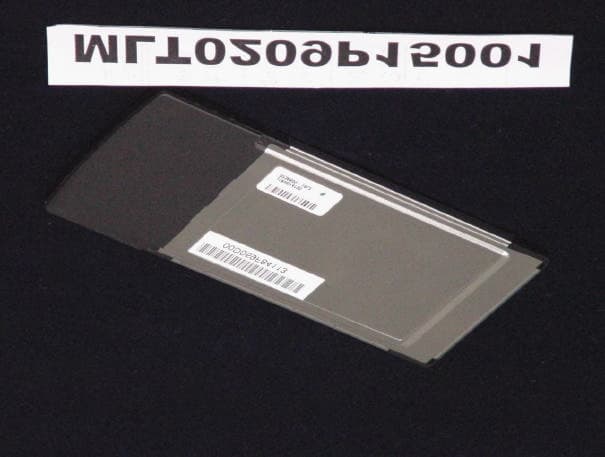
Click to zoom
Application Details
- Equipment Class
- DTS - Digital Transmission System
- Date of Grant
- Oct 17, 2002
- Application Purpose
- Original Equipment
- Date of Application
- Oct 17, 2002
- Equipment Note
- Wireless LAN PCMCIA Card
- Frequency Range
- 2412.00000000 - 2462.00000000
- Country
- Taiwan
Documents & Files
Document Text
Text extracted from the exhibit documents filed with the FCC. Open a document above to read the original.
Users Manual
Wireless PCMCIA Card User Manual Chapter 1 About the Wireless PCMCIA Card...........................3 1-1 Features...........................................................................3 1-2 Applications....................................................................3 1-3 Product Kit......................................................................4 Chapter 2 Network Configuring and Planning..........................5 2-1 Network Topology..........................................................5 2-2 Roaming..........................................................................7 Chapter 3 Installation.................................................................8 3-1 System Requirements......................................................8 3-2 Inserting the Wireless Card.............................................8 3-3 Installation and Uninstall Process...................................8 Chapter 4 Wireless Utility and Configuration.........................15 4-1 Windows 98/ME/2000 Wireless Utility........................15 4-2 Windows XP Wireless Utility.......................................20 Appendix A Troubleshooting...................................................27 Appendix B Glossary...............................................................28 Appendix C Specifications for Wireless Card.........................29 Chapter 1 About the Wireless PCMCIA Card This IEEE 802.11b Wireless PCMCIA Card is compatible with notebook computer Type II or Type III PCMCIA slot. As a Plug-and-Play device, Windows 98/2000/ME/XP will automatically recognize the wireless PCMCIA Card and initiate the installation process. Upon successful installation, the wireless PCMCIA Card will communicate seamlessly with other IEEE 802.11b wireless products. 1-1 Features 1. Supports up to 11 Mbps data rate. 2. Supports point-to-point and point-to-multipoint access provides increased flexibility. 3. Seamless connectivity to wired Ethernet and PC network LAN’s offers quick, trouble-free integration with existing networks. 4. Direct Sequence Spread Spectrum (DSSS) technology provides secure wireless connection. 5. Wireless connections eliminate the hassle and cost of cabling. 6. Supports a wide range of LAN (Local Area Network) Network Operating Systems (NOS) including Windows 98/2000/ ME/XP 7. Easy Plug and Play installation. 8. Omni - directional antenna provides wide range of reception. 9. Greater flexibility to locate or move networked PC’s 10. PCMCIA will support a ACTIVITY LED for feedback to the user on the current WLAN activity state. The signaling shall reflect the activity as follows: 1-2 Applications This wireless PCMCIA cards offer a fast, reliable, cost-effective solution for wireless client access to the network. Refer below for examples : l Remote access to corporate network information l E-mail, file transfer and terminal emulation l Difficult-to-wire environments l Historic or older buildings without Ethernet wiring. l Buildings with asbestos insulation l Open areas where wiring is difficult to employ l Re-layout frequently environments l Retailers, manufacturers or other organizations that frequently rearrange the workplace or relocate l Temporary LANs for special projects or peak time usage l Trade shows, exhibitions and construction sites that employ temporary networks. l Retailers, airline and shipping companies that need additional workstations for a peak period and auditors that require workgroups at customer sites. l Access to database for mobile workers l Medical, technical and retail specialists that require roaming access to a database or other network resources. l SOHO (Small Office and Home Office) users l Perfect for users that need a small, easy-to-install network that deploys rapidly. 1-3 Product Kit The wireless PCMCIA card includes the following items. Ensure that the items in the following list have been included. If any of the listed items are missing, please contact your local dealer. l One wireless PCMCIA Type II PCMCIA card l One Compact Disk. The CD include 98/2000/ME/XP driver, utility and user manual Chapter 2 Network Configuring and Planning The wireless PCMCIA card supports legacy Ethernet LAN network configuration options as defined by the IEEE 802.11b. The wireless PCMCIA card can be configured as: . Ad-Hoc mode for no Access Point wireless environment. . Infrastucture mode for wireless environment with Access Point. 2-1 Network Topology An Ad-Hoc wireless LAN is a group of computers. Each computer equipped with a wireless PCMCIA card that configure to same radio channel in order to communicate with others. Ad-Hoc wireless LAN configurations are appropriate for branch level departments or SOHO operations. A group of wireless users and an Access Point compose a Basic Service Set (BSS). Wireless clients can talk to any computer in both wired and wireless LAN network via the Access Point. 2-2 Roaming Infrastructure mode also supports roaming capabilities for mobile users. More than one BSS can be configured as an Extended Service Set (ESS). The continuous network allows users to roam freely within ESS. All wireless PCMCIA cards and Access Point within one ESS must be configured with the same ESSID in order to utilize roaming function. Properly Access Point positioning with a clear radio signal can greatly enhance wireless performance. Chapter 3 Installation 3-1 System Requirements In order to install and use the wireless PCMCIA card in your notebook computer. Your notebook system must meet the following requirements: l A PCMCIA Type II Slot l Compact Disk Device 3-2 Inserting the Wireless Card 1. Locate an available Type II PCMCIA slot. 2. With the PCMCIA card pin connector facing the PCMCIA slot, you can easily insert the card into the slot. 3. After properly inserting the wireless card, you can continue with wireless driver and utility installation. 3-3 Installation and Uninstall Process Install AMBIT Wireless LAN (Windows 98/2K/ME/XP) 1. Execute t…
Text truncated - open the document above for the full version.
External Photos
MAX LIGHT Report Number: MLT0209P15001 FCC ID: MCLT60H625 Technology Lab MAX LIGHT Report Number: MLT0209P15001 FCC ID: MCLT60H625 Technology Lab
ID Label/Location Info
MAX LIGHT Report Number: MLT0209P15001 FCC ID: MCLT60H625 Technology Lab Label Format: Label Position: This device complies with Part15 of the FCC Rules. Operation is subject to the following two conditions: (1) This device may not cause harmful interference,and (2) This device must accept any interference received ,including. Interference that may cause undesired operation. Model : T60H625 FCC ID : MCLT60H625 MADE IN TAIWAN Rear View Equipment Lable 4.5cmX3.0cm
Internal Photos
MAX LIGHT Report Number: MLT0209P15001 FCC ID: MCLT60H625 Technology Lab MAX LIGHT Report Number: MLT0209P15001 FCC ID: MCLT60H625 Technology Lab MAX LIGHT Report Number: MLT0209P15001 FCC ID: MCLT60H625 Technology Lab MAX LIGHT Report Number: MLT0209P15001 FCC ID: MCLT60H625 Technology Lab
Operational Description
1 TM Processing Gain for Direct Sequence Spread Spectrum Communication Systems and PRISM® Introduction This application note addresses the concept of processing gain (PG) of Direct Sequence Spread Spectrum (DSSS) systems. The PRISM chipset is used to implement DSSS radio designs. The processing gain provides the unique properties to the DSSS waveform primarily in terms of interference tolerance. The PG of a DSSS system is centered around the utilization of random codes which are used in conjunction with the data. These random codes are referred as Pseudo Noise (PN) codes. The HSP3824 provides this coding capability for the PRISM. Description In a DSSS system random binary data with a bit rate ofr b bits per sec (bps) is multiplied (Exclusive Ored) by a pseudorandom binary waveform, which is at much higher rate and it provides the frequency spreading operation. This pseudorandom (PN) binary source outputs symbols called chips at a constant chip rate r C chips per sec (cps). This is a random, noise like signal and hence the name PN signal. The chip rate is always higher than the bit rate, and the ratio of the chip rate to the bit rate is defined as the processing gain (PG) [3]. The PG is a true signal to jammer (interference) ratio at the receiver after the despreading operation (removal of PN). The rate of the PN code is the one that defines the bandwidth of the transmitted spread waveform. The receiver of a DSSS system must remove the spreading as the first step in the demodulation process. During the despreading operation the receiver must generate a phase locked exact replica of the pseudorandom spreading waveform to match the transmitted signal. This is achieved by the code acquisition, and code tracking loops embedded in the HSP3824. The receiver PN sequence must be exactly in phase with the transmitted PN sequence, and this is achieved by correlation techniques. DSSS Transceiver A DSSS transmitter is shown in Figure 1. The data is denoted by d(t), the spreading signal is denoted by c(t), and the spread waveform q(t) is fed to the BPSK modulator operating at a carrier frequency f C , and the transmitted signal is denoted by x(t). A text book conceptual block diagram of a DSSS receiver is depicted in Figure 2. Note that PRISM is architected to perform the despreading function at baseband (HSP3824) rather than at RF as shown on Figure 2. This example is used for illustration of the concept and not to reflect the actual PRISM implementation. The received signal for this text book example is the combination of the transmitted spread spectrum signal and a narrow band jammer x J (t). The locally generated despreading sequence is denoted by c’(t), and should be equal to c(t). The despread signal is then band pass filtered before data demodulation and d’(t) should be equal to d(t). PG Benefits The primary benefit of processing gain is its contribution towards jamming resistance to the DSSS signal. The PN code spreads the transmitted signal in bandwidth and it makes it less susceptible to narrowband interference within the spread BW. The receiver of a DSSS system can be viewed as unspreading the intended signal and at the same time spreading the interfering waveform. This operation is best illustrated on Figure 3. Figure 3 depicts the power spectral density (psd) functions of the signals at the receiver input, the despread signal, the bandpass filter power transfer function, and the band pass filter output. Figure 3 graphically describes the effect of the processing gain on a jammer. The jammer is narrow, and has a highly peaked psd, while the psd of the DSSS is wide and low. The despreading operation spreads the jammer power psd and lowers its peak, and the BPF output shows the effect on the signal to jammer ratio. FIGURE 16. DSSS TRANSMITTER d(t) q(t) c(t) x(t) COS(ω O t) CODE GENERATOR FIGURE 17. DSSS RECEIVER d’(t)y(t) c’(t) x(t) + x j (t) COS(ω O t) PN GENERATOR BPF H(f) x’(t) LPF Application Note Authors: John Fakatselis 1-888-INTERSIL or 321-724-7143|Intersil and Design is a trademark of Intersil Corporation.|Copyright © Intersil Corporation. 2000 PRISM® is a registered trademark of Intersil Corporation. PRISM and design is a trademark of Intersil Corporation. 2 If for example, BPSK modulation is used and an Eb/No of lets say 14dB is required to achieve a certain BER performance, when this waveform is spread with a processing gain of 10dB then the receiver can still achieve its required performance with the signal having a 4dB power advantage over the interference. This is derived from the 14dB required minus the 10dB of PG. The higher the processing gain of the DSSS waveform the more the resistance to interference of the DSSS signal. The classical definition of processing gain is the 10 Log number [r C /r B ] in dB. By this definition a system that has a data rate of 1MBPS and a chip rate (rate of PN code) of 1MCPS will have a PG of 10.41dB. Using the PRISM chip set each data bit is x-ored with an 11 bit sequence for this particular example. The processing gain can be then viewed as the 10Log[11]dB where 11 is the length of the PN code. If a code with a length of 16 bits is to be used then the processing gain is equivalent to 10 Log[16] dB or 12.04dB. To this end these PN signals must posses certain mathematical properties to be useful as part of a DSSS system. Primarily the PN codes that are useful must have very good autocorrelation and crosscorrelation properties as well as maintaining some randomness properties. The DSSS receiver is utilizing a reference PN sequence which is a replica to the transmitted sequence and when it detects correlation between the reference and the incoming sequences it declares initial acquisition and it establishes initial symbol timing. Any partial correlations can result to false acquisitions and degradation to the receiver performance. This is why the PN code must have good correlation properties. Some of the PN code classes with such properties are d…
Text truncated - open the document above for the full version.
Test Report
P P a a r r t t 1 1 5 5 S S u u b b p p a a r r t t B B & & C C ( ( 1 1 5 5 . . 2 2 4 4 7 7 ) ) Product : Wireless PCMCIA Card Manufacture : AMBIT Microsystems Corporation. FCC ID : MCLT60H625 Model : T60H625 Report No. : MLT0209P15001 Test Date : September 12.2002 Test By Max Light Technology Co.,Ltd. Room 5, 8F, No.125, Section 3 Roosevelt Road, Taipei, Taiwan., R.O.C. Tel: 886-2-2363-2447 Fax: 886-2-2363-2597 T T h h e e t t e e s s t t r r e e p p o o r r t t c c o o n n s s i i s s t t s s o o f f 7 7 0 0 p p a a g g e e s s i i n n t t o o t t a a l l . . I I t t m m a a y y b b e e d d u u p p l l i i c c a a t t e e d d c c o o m m p p l l e e t t e e l l y y f f o o r r l l e e g g a a l l u u s s e e w w i i t t h h t t h h e e a a l l l l o o w w a a n n c c e e o o f f t t h h e e a a p p p p l l i i c c a a n n t t . . I I t t s s h h a a l l l l n n o o t t b b e e r r e e p p r r o o d d u u c c e e d d e e x x c c e e p p t t i i n n f f u u l l l l , , w w i i t t h h o o u u t t t t h h e e w w r r i i t t t t e e n n a a p p p p r r o o v v a a l l o o f f o o u u r r l l a a b b o o r r a a t t o o r r y y . . MAX LIGHT MEASUREMENT REPORT Page: 2/70 Report Number: MLT0209P15001 FCC ID: MCLT60H625 Technology Lab Table of Contents : MAX LIGHT MEASUREMENT REPORT Page: 3/70 Report Number: MLT0209P15001 FCC ID: MCLT60H625 Technology Lab CERTIFICATION We here by verify that : The test data, data evaluation, test procedures and equipment configurations shown in this report were made in accordance with the procedures given in ANSI C63.4-1992. All test were conducted by MLT(Max Light Technology Co.,Ltd) Room 5, 8F, No.125, Section 3 Roosevelt Road, Taipei, Taiwan, R.O.C Also, we attest to the accuracy of each. We further submit that the energy emitted by the sample EUT tested as described in the report is in compliance with Class B radiated and conducted emission limit of FCC Rules Part 15 Subpart B & C (15.247). EUT : Wireless PCMCIA Card Applicant : AMBIT MICROSYSTEMS CORPORATION. 5F-1, 5 Hsin-An Road, Hsinchu Scicnce- Based Industrial Park, Taiwan Manufacturer : AMBIT MICROSYSTEMS CORPORATION. 5F-1, 5 Hsin-An Road, Hsinchu Scicnce-Based Industrial Park, Taiwan Model No : T60H625 FCC ID : MCLT60H625 Prepared by : Approved by : MAX LIGHT MEASUREMENT REPORT Page: 4/70 Report Number: MLT0209P15001 FCC ID: MCLT60H625 Technology Lab 1.1 Introduction The following measurement report is submitted on behalf of AMBIT Microsystems Corporation. . In support of a Class B Digital Device certification in accordance with Part2 Subpart J and Part 15 Subpart A And B&C of the Commission’s and Regulations. 1.2 Description of EUT EUT : Wireless PCMCIA Card Applicant : AMBIT MICROSYSTEMS CORPORATION. 5F-1, 5 Hsin-An Road, Hsinchu Scicnce- Based Industrial Park, Taiwan Manufacturer : AMBIT MICROSYSTEMS CORPORATION. 5F-1, 5 Hsin-An Road, Hsinchu Scicnce-Based Industrial Park, Taiwan Model No : T60H625 FCC ID : MCLT60H625 Power Type : Powered by PC Frequency of Channel : See Next page Type of Modulation : Direct Sequence Spread Spectrum Type of Antenna : Printed Antenna During testing the EUT was operated at Tx or Rx mode for each emission measured. This was done in order to ensure that maximum emission levels were attained. MAX LIGHT MEASUREMENT REPORT Page: 5/70 Report Number: MLT0209P15001 FCC ID: MCLT60H625 Technology Lab Frequency of Each Channel (Working Frequency) Channel No. Frequency (MHz) 01 2412 02 2417 03 2422 04 2427 05 2432 06 2437 07 2442 08 2447 09 2452 10 2457 11 2462 MAX LIGHT MEASUREMENT REPORT Page: 6/70 Report Number: MLT0209P15001 FCC ID: MCLT60H625 Technology Lab 1.3 Summary Of Tests 47 CFR Part 15 Subpart C Reference Test Results Note 15.107 AC Power Conducted Emission PASS 15.247(c) Transmitter Radiated Emissions PASS 15.247(b) Max. Output Power PASS 15.247(a)(2) 6dB RF Bandwidth PASS 15.247(d) Max. Power Density PASS 15.247(c) Out of Band Conducted Spurious Emission PASS 15.247(c) Band Edge Measurement PASS 15.247(e) Processing Gain of Direct Sequence PASS Provided by Applicant 15.203 Antenna Requirement PASS MAX LIGHT MEASUREMENT REPORT Page: 7/70 Report Number: MLT0209P15001 FCC ID: MCLT60H625 Technology Lab 1.4 Description of Support Equipment In order to construct the minimum system which required by the ANSI C63.4-1991, following equipments were used as the support units. Computer : COMPAQ Model No. : Prescrio 1700 Serial No. : 54S32009A1 FCC ID : FCC(DOC) Keyboard(USB) : SOLID YEAR Model No. : KB-A21S3 Serial No. : DF3DW301 FCC ID : FCC(DOC) Monitor : IBM Model No. : 10L6145 030 Serial No. : 23-092079 FCC ID : ARSCM569N Mouse(USB) : APPLE Model No. : M4848 Serial No. : AS82201 FCC ID : FCC(DOC) Printer : PANASONIC Model No. : KX-P1080I Serial No. : 7CKAKE98933 FCC ID : ACJ5Z6KX-P10801 Mic : KAKA Model No. : K186 Serial No. : 7H0101A FCC ID : N/A MAX LIGHT MEASUREMENT REPORT Page: 8/70 Report Number: MLT0209P15001 FCC ID: MCLT60H625 Technology Lab Earphone : KAKA Model No. : WA67JH Serial No. : JH87902 FCC ID : N/A MAX LIGHT MEASUREMENT REPORT Page: 9/70 Report Number: MLT0209P15001 FCC ID: MCLT60H625 Technology Lab 1.4 Configuration of System Under Test During testing the EUT(Wireless PCMCIA Card) was to plug in PCMCIA port of COMPAQ notebook computer. A mouse(USB) & keyboard (USB) were connected to the USB port of COMPAQ notebook computer. And a printer was connected to the parallel port. A external monitor connected the VGA port and the Mic & Earphone were connected with the audio jack of COMPAQ notebook computer.. TEST SITE Power Supply Note book PC Monitor Printer Mic Keyboard Mouse EUT Earphone RS-232 RS-232 RJ-45 Cable USB Cable RJ-11 Cable MAX LIGHT MEASUREMENT REPORT Page: 10/70 Report Number: MLT0209P15001 FCC ID: MCLT60H625 Technology Lab 1.6 Test Procedure All measurements contained in this report were performed according to the techniques described in Measurement procedure ANSI C63.4-1992 "Measurement of unIntentional Radiators." 1.7 General Test Conditio…
Text truncated - open the document above for the full version.
Test Setup Photos
MAX LIGHT MEASUREMENT REPORT Page: 12/70 Report Number: MLT0209P15001 FCC ID: MCLT60H625 Technology Lab 2.3 Test Configuration: Front View of The Test Configuration MAX LIGHT MEASUREMENT REPORT Page: 13/70 Report Number: MLT0209P15001 FCC ID: MCLT60H625 Technology Lab Rear View of The Test Configuration MAX LIGHT MEASUREMENT REPORT Page: 22/70 Report Number: MLT0209P15001 FCC ID: MCLT60H625 Technology Lab 3.3 Test Configuration: Front View of The Test Configuration MAX LIGHT MEASUREMENT REPORT Page: 23/70 Report Number: MLT0209P15001 FCC ID: MCLT60H625 Technology Lab Rear View of The Test Configuration
Contact Information
Applicant
Mrs. Rio Chen(Compliance Deputy Manager)
Test Firm
Max Light Technology Co., Ltd.Jesse Tien
Technical Specifications
| # | Rule Parts | Frequency Range | Power Output |
|---|---|---|---|
| 1 | 15C | 2.41 GHz - 2.46 GHz | 22.00 mW |
Other Applications from HON HAI Precision Ind. Co., Ltd.

MCLT77W968
Jun 03, 2021LTE M.2 Module
Equipment Class
CBE - Citizens Band End User Devices
MCLT77W968C9
Feb 13, 2020LTE M.2 Module
Equipment Class
PCB - PCS Licensed Transmitter
MCLADB1761WF
Jun 03, 2015IP Set-Top Box with Wi-Fi 11ac
Equipment Class
DTS - Digital Transmission System
MCLADB1761W
Jun 02, 2015IP Set-Top Box
Equipment Class
DTS - Digital Transmission System
MCLT77H566
Feb 16, 2015WiFi/BT Module
Equipment Class
DTS - Digital Transmission System