MCLT60N871802.11b/g MiniPCI Module
HON HAI Precision Ind. Co., Ltd.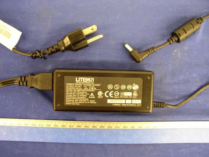
Click to zoom
Application Details
- Equipment Class
- DTS - Digital Transmission System
- Date of Grant
- Jun 22, 2004
- Application Purpose
- Original Equipment
- Date of Application
- Jun 22, 2004
- Equipment Note
- 802.11b/g MiniPCI Module
- Frequency Range
- 2412.00000000 - 2462.00000000
- Country
- Taiwan
Documents & Files
Document Text
Text extracted from the exhibit documents filed with the FCC. Open a document above to read the original.
Users Manual
1 Trade Name : T60N871 802.11b/g Wireless LAN MiniPCI module User Manual 2 1. Wireless LAN Configuration Utility Introduction The Wireless LAN Configuration Utility is a powerful application that helps you to configure FOXCONN WLAN card and monitor the statistics of the communication status. Unlike the standard method of configuring the card via the operating system utilities, this application permits the dynamic modification of the configuration parameters while the card is operating. It also offers more configuration options. FOXCONN offers the Wireless LAN Configuration Utility for Windows 95/98/Me/2000/XP. 3 1.1 How to install the driver and Wireless LAN Configuration Utility Double click the “setup” located in “\WLAN_Utility\” Fig 1-1 The program will automatically proceed with installing. Press “Next” to continue. Fig 1-2 4 Press “I accept the terms in the license agreement” to continue the install shield. Or press “I do not accept the terms in the license agreement” quit install process. Then, press “Next” to continue. Fig 1-3 Press “Install” to continue installing Fig 1-4 5 Install Shield is processing Fig 1-5 Choose “Finish” to complete the installation Fig 1-6 6 The usage of Wireless LAN Configuration Utility 2.1 Introduction The Wireless LAN Configuration Utility appears as an icon on the system tray of Windows while the card is running. You can open it by double clinking the icon (Fig 2-1) to show full screen of WLAN Utility. Fig 2-1 icon on the system tray While the station is in infrastructure mode and not associated to an Access Point, the color of the icon is “White (blank)”(Fig 2-2). Fig 2-2 No Connection As soon as the station associates to an Access Point, the icon color automatically turns to “Green”, “Yellow” or “Red”. Which indicates the receiving signal strength from Access Point. “Green” (Fig 2-3) indicates the signal is “Good”. “Yellow”(Fig 2-4) indicates the signal is “Fair”. “Red”(Fig 2-5) indicates the signal is “Poor”. Fig 2-3 Good Connection Fig 2-4 Fair Connection Fig 2-5 Poor Connection The Wireless LAN Configuration Utility is a powerful and highly integrated application include the following options (tabs), Status Site Survey Statistics About 7 2.2.1 Status A typical screen of the application in Infrastructure mode is shown in Fig 2-6. The Wireless LAN Configuration Utility contains the following information for Wireless LAN. Profile: The profile name which user selected. If there is no profile selected, it would show “default”. SSID: The Network Service Set Identification provided by Access Point. Link Status: The MAC address of Access Point. Network Type: Infrastructure or Ad-Hoc. Channel: Operation channel provided by Access Point. Tx (Transmit ion) Rate: Current transmit ion rate. Signal Strength: The Signal level of Wireless Network. Link Quality: The Signal Quality of Wireless Network. Network Address: shows the current Network status such as MAC address (Wireless Card), DHCP (Enable or not), IP address, Subnet Mask address, Gateway Address and DNS server address. Fig 2-6 Typical screen of the Wireless LAN Configuration Utility in Infrastructure mode. Users can change the configuration by clicking the “Configuration” Button. 8 2.2.2 Configuration Users can edit Wireless Network setting by pressing “Configuration” button. There are 3 tabs in “Configuration”. General Encryption Advance 9 2.2.2.1 General Page General Page include the following options, (See Fig 2-7) Profile Name: Name of Selected Profile. (Default profile name: default). If users want to change settings of profile, please refer to Edit Profile option in “Site Survey” page. Network Type: User can choose either Infrastructure or Ad-Hoc mode. SSID: Define the SSID. Channel: Provided by Access Point in Infrastructure mode. User can only define when choose Ad-Hoc mode in Network Type option. Desired Rate: User can choose the desired rate from 1Mbps~11Mbps (associated with 802.11b Access Point) and 1Mbps~54Mbps (associated with 802.11g Access Point). (Default Setting: Automatic). Fig 2-7 10 2.2.2.2 Encryption Page IPN2220 WLAN Utility provides powerful and intelligent setting of WEP Key. The Encryption page include the following options, (see Fig 2-8) Encryption Mode: User can choose WEP On or None WEP for the Network. This option will be automatically defined after “Site Survey”. Authentication: There are 2 modes of Authentication of 802.11b/g Wireless Network. Open System and Share Key. These are defined by Access Point. IPN2220 WLAN Utility provides the “Auto Switch” option for easy to use. This option can be also automatically defined after “Site Survey”. WEP Key Entry (hex): Users have 4 sets of WEP to use. Each will need to be defined by user according to Access Point. The Key value is in Hex format (from 0~9, a~f). Encryption Key Length: User can choose 64bits, 128bits or 152bits encryption for the network according Access Point. Fig 2-8 11 2.2.2.3 Advance Page Advance Page provides more advanced options for Wireless Network. This include the followings, (See Fig 2-9) Power Saving: Enable or Disable the Power Saving Mode. (Default: Disable) Preamble Type: User can choose Long Preamble or Short Preamble type according to Access Point. IPN2220 provides “Auto” setting for choosing “Preamble Type”. Fragment Threshold: RTS Threshold: Receive Antenna: Fig 2-9 12 2.2.3 Site Survey IPN2220 WLAN Utility provides the easy to link “Site Survey” option. This will allow users to connect to Access Point intelligently. By choosing the Site Survey option, you can scan all the channels to find all the Access Points within the range of card. The list includes information about the BSSID and SSID of the access point(s), the Mode (Network Type), whether or not WEP encryption is used, Channel, Signal Strength and Support Rate. In order to update this list, press the “Rescan” button. The “Site Survey” page include, (See Fig 2-10) Available Netw…
Text truncated - open the document above for the full version.
Attestation Statements
HON HAI PRECISION IND. CO., LTD. HSINCHU SCIENCE PARK BRANCH OFFICE MIN SHENG PLANT 5F-1, 5 Hsin-An Road 4-1 Ming-Sheng St., Hsinchu, Science-Based Industrial Park Tu-Cheng Industrila Area, Taiwan, R.O.C. Taiwan, R.O.C TEL:+886-3-5784975 TEL:+886-2-2267 6511 FAX:+886-3-5775100 FAX:+886-2-2267 6512 Declaration Letter HON HAI Precision IND.CO.,LTD. hereby declare that product T60N871 fixed the firmware in EEPOM and only allow end user in USA to use limited the CH 1 ~CH11 and within frequency range 2400~2483.5 MHz. The firmware is fixed in the EEPOM on the product "T60H871" and only manufacturer engineer could access and modify it. End user is impossible to access this firmware and EEPOM to modify it. Sincerely, Rio Chen Deputy Manager, Compliance HON HAI Precision IND.CO.,LTD. Date: June 17, 2004
Cover Letter(s)
HON HAI PRECISION IND. CO., LTD. HSINCHU SCIENCE PARK BRANCH OFFICE MIN SHENG PLANT 5F-1, 5 Hsin-An Road 4-1 Ming-Sheng St., Hsinchu, Science-Based Industrial Park Tu-Cheng Industrila Area, Taiwan, R.O.C. Taiwan, R.O.C TEL:+886-3-5784975 TEL:+886-2-2267 6511 FAX:+886-3-5775100 FAX:+886-2-2267 6512 Federal Communications Commission Authorization and Evaluation Division Confidentiality Request regarding application for certification of FCC ID: (MCLT60N871) Pursuant to Sections 0.457 and 0.459 of the Commission’s Rules, we hereby request confidential treatment of information accompanying this application as outlined below: (List exhibits here) 1. Schematic 2. Layout 3. Block Diagram 4. BOM 5. Theory of Operation The above materials contain trade secrets and proprietary information not customarily released to the public. The public disclosure of these materials may be harmful to the applicant and provide unjustified benefits to its competitors. The applicant understands that pursuant to Section 0.457 of the Rules, disclosure of this application and all accompanying documentation will not be made before the date of the Grant for this application. Sincerely, (Signature) : (Printed name) : Rio Chen Title : Compliance Deputy Engineer
External Photos
EXHIBIT C - EUT EXTERNAL PHOTOGRAPHS Notebook Computer – Top View Notebook Computer – Bottom View Power Adapter View Antenna Location View I Antenna Location View II
ID Label/Location Info
EXHIBIT A - FCC ID LABEL INFORMATION Proposed FCC ID Label Proposed Label Location on EUT Bottom Side of EUT/FCC ID Label This device contains FCC ID: MCLT60N871 This device complies with Part 15 of the FCC Rules. Operation is subject to the following two conditions: (1) this device may not cause harmful interference, and (2) this device must accept any interference received, including interference that ma y cause undesired operation.
Internal Photos
EXHIBIT C - EUT INTERNAL PHOTOGRAPHS EUT Location View I EUT Location View II EUT – Component View EUT – Component Cover Removed View EUT – Solder View
Test Report
Note: The test report is specially limited to the above company and the product model only. It may not be duplicated without prior written consent of Bay Area Compliance Laboratory Corporation. This report must not be used by the client to claim product certification, approval, or endorsement by NVLAP, NIST or any agency of the US Government. FCC PART 15.247 EMI MEASUREMENT AND TEST REPORT For HON HAI PRECISION IND. CO., LTD. HSINCHU SCIENCE PARK BRANCH OFFICE 5F-1, 5 Hsin-An Road, Hsinchu, Science-Based Industrial Park, Taiwan, R.O.C. FCC ID: MCLT60N871 This Report Concerns: Original Report Equipment Type: 802.11 b/g MiniPCI Module Test Engineer: Ming Jing / Report No.: R0405203 Report Date: 2004-06-08 Reviewed By: Ling Zhang / Prepared By: Bay Area Compliance Laboratory Corporation (BACL) 230 Commercial Street Sunnyvale, CA 94085 Tel: (408) 732-9162 Fax: (408) 732 9164 HON HAI PRECISION IND. CO., LTD. FCC ID: MCLT60N871 Report # R0405203Rpt.doc Page 2 of 47 FCC Part 15.247 Test Report TABLE OF CONTENTS GENERAL INFORMATION.......................................................................................................................................4 PRODUCT DESCRIPTION FOR EQUIPMENT UNDER TEST (EUT) ....................................................................................4 OBJECTIVE...................................................................................................................................................................4 RELATED SUBMITTAL(S)/GRANT(S).............................................................................................................................4 TEST METHODOLOGY..................................................................................................................................................4 TEST FACILITY.............................................................................................................................................................5 SYSTEM TEST CONFIGURATION ..........................................................................................................................6 JUSTIFICATION.............................................................................................................................................................6 EUT EXERCISE SOFTWARE..........................................................................................................................................6 SPECIAL ACCESSORIES.................................................................................................................................................6 SCHEMATICS / BLOCK DIAGRAM.................................................................................................................................6 EQUIPMENT MODIFICATIONS.......................................................................................................................................6 CONFIGURATION OF TEST SYSTEM..............................................................................................................................7 TEST SETUP BLOCK DIAGRAM.....................................................................................................................................7 SUPPORT EQUIPMENT LIST AND DETAILS....................................................................................................................8 EXTERNAL I/O CABLING LIST AND DETAILS...............................................................................................................8 POWER SUPPLY INFORMATION.....................................................................................................................................8 SUMMARY OF TEST RESULTS ...............................................................................................................................9 §1.1307(B)(1) & §2.1091 - RF EXPOSURE...............................................................................................................10 §15.203 - ANTENNA REQUIREMENT....................................................................................................................11 STANDARD APPLICABLE............................................................................................................................................11 §15.207(A) - CONDUCTED EMISSIONS.................................................................................................................12 MEASUREMENT UNCERTAINTY..................................................................................................................................12 EUT SETUP................................................................................................................................................................12 SPECTRUM ANALYZER SETUP....................................................................................................................................12 TEST EQUIPMENT LIST AND DETAILS.........................................................................................................................12 TEST PROCEDURE......................................................................................................................................................12 SUMMARY OF TEST RESULTS.....................................................................................................................................13 CONDUCTED EMISSIONS TEST DATA.........................................................................................................................13 PLOT OF CONDUCTED EMISSIONS TEST DATA...........................................................................................................13 §15.209(A) - SPURIOUS EMISSION ........................................................................................................................16 STANDARD APPLICABLE.............................................................................…
Text truncated - open the document above for the full version.
Test Setup Photos
EXHIBIT B - TEST SETUP PHOTOGRAPHS Conducted Emission - Front View Conducted Emission - Side View Radiated Emission - Front View Radiated Emission - Rear View
Contact Information
Applicant
Mrs. Rio Chen(Compliance Deputy Manager)
Test Firm
Bay Area Compliance LaboratoryJohn Chan
Technical Specifications
| # | Rule Parts | Frequency Range | Power Output |
|---|---|---|---|
| 1 | 15C | 2.41 GHz - 2.46 GHz | 145.00 mW |
Other Applications from HON HAI Precision Ind. Co., Ltd.

MCLT77W968
Jun 03, 2021LTE M.2 Module
Equipment Class
CBE - Citizens Band End User Devices
MCLT77W968C9
Feb 13, 2020LTE M.2 Module
Equipment Class
PCB - PCS Licensed Transmitter
MCLADB1761WF
Jun 03, 2015IP Set-Top Box with Wi-Fi 11ac
Equipment Class
DTS - Digital Transmission System
MCLADB1761W
Jun 02, 2015IP Set-Top Box
Equipment Class
DTS - Digital Transmission System
MCLT77H566
Feb 16, 2015WiFi/BT Module
Equipment Class
DTS - Digital Transmission System