MCQ50M1355Communication Bridge
Digi International Inc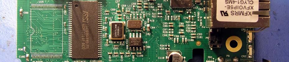
Click to zoom
Application Details
- Equipment Class
- DTS - Digital Transmission System
- Date of Grant
- Apr 24, 2007
- Application Purpose
- Original Equipment
- Date of Application
- Apr 16, 2007
- Equipment Note
- Communication Bridge
- Frequency Range
- 2412.00000000 - 2462.00000000
- Company
- Digi International Inc
- Country
- United States
Documents & Files
Document Text
Text extracted from the exhibit documents filed with the FCC. Open a document above to read the original.
Users Manual
Part number/version: 90000789_B Release date: January 2007 www.digiembedded.com ConnectCore ™ 9C/Wi-9C . . . . . . . . . . . . . . . . . . . . . . . . . . . . . . . . . . . . . . . . . . . . . . . . . . . . . . . . . . . . . . . . . . Hardware Reference Digi International, Inc. 11001 Bren Road East Minnetonka, MN 55343 U.S.A. United States: +1 877 912-3444 Other locations: +1 952 912-3444 www.digiembedded.com ©2005-2007 Digi International Inc. Printed in the United States of America. All rights reserved. Digi, Digi International, the Digi logo, NetSilicon, a Digi International Company, Jump Start Kit, ConnectCore, NET+, NET+OS and NET+Works are trademarks or registered trademarks of Digi International, Inc. in the United States and other countries worldwide. All other trademarks are the property of their respective owners. Information in this document is subject to change without notice and does not represent a committment on the part of Digi International. Digi provides this document “as is,” without warranty of any kind, either expressed or implied, including, but not limited to, the implied warranties of, fitness or merchantability for a particular purpose. Digi may make improvements and/or changes in this manual or in the product(s) and/or the program(s) described in this manual at any time. This product could include technical inaccuracies or typographical errors. Changes are made periodically to the information herein; these changes may be incorporated in new editions of the publication. iii Contents . . . . . . . . . . . . . . . . . . . . . . . . . . . . . . . . . . . . . . . . . . . . . . . . . . . . . . . . . . . . . . . . . . . . . Chapter 1: About the Modules............................................................... 1 Common module features ...............................................................1 Wi-9C specific features ..................................................................2 Memory.....................................................................................2 Memory clocks ............................................................................2 Other system clocks ......................................................................2 Interfaces .........................................................................................2 Ethernet....................................................................................2 WLAN .......................................................................................3 USB 2.0 Host and Device.................................................................3 Serial .......................................................................................4 I2C ..........................................................................................4 External Memory bus .....................................................................4 LCD..........................................................................................4 ConnectCore 9C configurations ...............................................................5 Configuration diagrams ..................................................................5 ConnectCoreWi-9C configurations ............................................................7 Configuration diagrams ..................................................................7 Chapter 2: What’s on the Module?......................................................11 Module layout .................................................................................. 11 Ethernet connector ........................................................................... 12 Ethernet connector pins ............................................................... 12 Ethernet LEDs ........................................................................... 12 802.3af Power over Ethernet (PoE) pass-through connector, P5 .................................................................................. 13 Connector description ................................................................. 13 PoE support.............................................................................. 13 Module LEDs .................................................................................... 14 Description .............................................................................. 14 ConnectCore Wi-9C default use....................................................................... 14 JTAG 20-pin header connector, P2 ......................................................... 15 Pin assignment .......................................................................... 15 JTAG adapter assembly....................................................................... 16 JTAG adapter............................................................................ 16 ivConnectCore 9C/Wi-9C Hardware Reference, Rev B 01/2007 Assembly ................................................................................. 17 USB Host connector, P6....................................................................... 18 Edge connector, P3............................................................................ 18 Pin assignment .......................................................................... 18 Pin assignment by SO-DIMM pin number ............................................ 19 Pin assignment by GPIO................................................................ 24 Antenna connectors: RP/SMA and U.FL (ConnectCore Wi-9C only) .................... 26 RP-SMA connectors, P10 and P8 ...................................................... 27 U.FL connectors, P11 and P9 ......................................................... 27 Chapter 3: About the Development Board........................................ 29 Features .................................................................................. 29 Basic description............................................................................... 30 Switches and buttons .…
Text truncated - open the document above for the full version.
Attestation Statements
TÜV America Inc. Phone: (651) 638-0297 19333 Wild Mountain Road Fax: (651) 638-0298 Taylor Falls, MN 55084 E-mail: [email protected] www.TUVamerica.com Management Service • Product Service • Industry Service • Automotive • BABT TÜV America Inc. is a subsidiary of TÜV SÜD Group. TÜV AMERICA INC 19333 WILD MOUNTAIN ROAD TAYLORS FALLS, MINNESOTA 55084-1786 ENGINEERING STATEMENT For Certification of Digi International Digi ConnectCore Wi9C Model No: 50001355-xx where xx can be any number from 0 thru 9 FCC ID: MCQ50M1355 FRN: 0010283307 IC: 1846A-50M1355 I am an Electromagnetic Compatibility Engineer for TÜV AMERICA INC, Taylors Falls, Minnesota. My education and experience are a matter of record with the Federal Communications Commission. TÜV AMERICA INC has been authorized by Frank Artner, Hardware Manager, of Digi International, to make Certification measurements of the above mentioned equipment. I attest that all testing done under my supervision was done in accordance with, and that the EUT fulfills the requirements of, the Federal Communications Commission's CFR 47 Part 15.247and Industry Canada's RSS210 Issue 6. Joel T. Schneider Senior Engineer Minnesota Wild River Lab TÜV America Product Service Tel: 651 604 4582 Fax: 651 638 0298 [email protected] Dated: 03 April 2007
Cover Letter(s)
Digi International 11001 Bren Road East Minnetonka, MN 55343 952-912-3444 tel 952-912-4991 central fax 03/27/2007 AmericanTCB 6731 Whittier Avenue McLean VA 22101 Attn: Director of Certification RE: FCC ID: MCQ-50M1355 / IC: 1846A-50M1355 submittal as modular device 1. The modular transmitter must have its own RF shielding. This is intended to ensure that the module does not have to rely upon the shielding provided by the device into which it is installed in order for all modular transmitter emissions to comply with Part 15 limits. It is also intended to prevent coupling between the RF circuitry of the module and any wires or circuits in the device into which the module is installed. Such coupling may result in non-compliant operation. The CC9W is designed such that all RF components and circuitry are placed on the top surface of the PCB. No RF related circuitry is present on the bottom surface of the PCB. a formed metal shield is soldered onto the top of the PCB and covers all RF components and circuitry. 2. The modular transmitter must have buffered modulation/data inputs (if such inputs are provided) to ensure that the module will comply with Part 15 requirements under conditions of excessive data rates or over-modulation. The user data enters the CC9W by way of several data ports: Ethernet, USB, serial, external 8 bit data buss. All of the user data that is to be transmitted over the modular transmitter is buffered by the CC9W’s baseband controller. The user’s data is packetized and transmitted at data rates that are completely controlled by the baseband controller and its software. The user has no access to either the baseband controller or its software. 3. The modular transmitter must have its own power supply regulation. This is intended to ensure that the module will comply with Part 15 requirements regardless of the design of the power supplying circuitry in the device into which the module is installed. The critical sections of the CC9W modular transmitter are powered by locally regulated 2.85V +/-5% low drop out regulators. These regulators are supplied from the system +3.3V power and are capable of maintaining a 2.85V +/-5% output with an input voltage of < 2.93V. The CC 9W will be forced into a hard reset if the system +3.3V falls to 2.93V and will cease to operate. 4. The modular transmitter must comply with the antenna requirements of Section 15.203 and 15.204(c). The antenna must either be permanently attached or employ a “unique” antenna coupler (at all connections between the module and the antenna, including the cable). Any antenna used with the module must be approved with the module, either at the time of initial authorization or through a Class II permissive change. The “professional installation” provision of Section 15.203 may not be applied to modules. The ConnectCore 9W uses two reverse polarity SMA (RP-SMA) antenna connectors. These connectors are designed with a male center pin which prevents a standard SMA connector from being mated to the ConnectCore 9W. 5. The modular transmitter must be tested in a stand-alone configuration, i.e., the module must not be inside another device during testing. This is intended to demonstrate that the module is capable of complying with Part 15 emission limits regardless of the device into which it is eventually installed. Unless the transmitter module will be battery powered, it must comply with the AC line conducted requirements found in Section 15.207. AC or DC power lines and data Digi International 11001 Bren Road East Minnetonka, MN 55343 952-912-3444 tel 952-912-4991 central fax input/output lines connected to the module must not contain ferrites, unless they will be marketed with the module (see Section 15.27(a)). The length of these lines shall be length typical of actual use or, if that length is unknown, at least 10 centimeters to insure that there is no coupling between the case of the module and supporting equipment. Any accessories, peripherals, or support equipment connected to the module during testing shall be unmodified or commercially available (see Section 15.31(i)). The CC9W module is designed to be compliant with all relevant FCC requirements without any additional shielding or filtering of any sort. As tested, the CC9W was mounted on top of a carrier board which provided the +3.3vdc to power the module and a RS232 line transceiver to allow serial data traffic. The carrier board drives the +3.3v from an on card dc to dc converter which is in turn powered by an external 12vdc power supply which is AC mains powered. There are no additional filters associated with the module/carrier board. Nor is there any additional shielding associated with is setup -- beyond the shield that is soldered to the module. 6. The modular transmitter must be labeled with its own FCC ID number, and, if the FCC ID is not visible when the module is installed inside another device, then the outside of the device into which the module is installed must also display a label referring to the enclosed module. This exterior label can use wording such as the following: “Contains Transmitter Module FCC ID: XYZMODEL1” or “Contains FCC ID: XYZMODEL1.” Any similar wording that expresses the same meaning may be used. The Grantee may either provide such a label, an example of which must be included in the application for equipment authorization, or, must provide adequate instructions along with the module which explain this requirement. In the latter case, a copy of these instructions must be included in the application for equipment authorization. The CC9W will have the FCC/IC id’s silk-screened in contrasting ink on the bottom of the PCB in the upper right corner using 0.06” text: Digi International 11001 Bren Road East Minnetonka, MN 55343 952-912-3444 tel 952-912-4991 central fax The following text will also appear in the hardware reference manual that ships with the CC9W: “If the FCC ID / IC ID is not visible when installed inside another …
Text truncated - open the document above for the full version.
Cover Letter(s)
TÜV America Inc. Phone: (651) 631-2487 1775 Old Highway 8 NW Fax: (651) 638-0285 Suite 104 E-mail: [email protected] New Brighton, MN 55112 www.TUVamerica.com Management Service • Product Service • Industry Service • Automotive • BABT TÜV America Inc. is a subsidiary of TÜV SÜD Group. 12 April 2007 American TCB 6731 Whittier Avenue McLean VA 22101 RE: Digi International Response to 4-9-07 Comments FCC ID: MCQ50M1355 1. ATCB Comments: The MPE calculations are missing for category mobile. Please upload RF Exposure exhibit using the formula supplied by the FCC. The distance must be 20 cm. The FCC will not accept anything but 20 cm. The equations would be: RESPONSE: Revised RF exposure letter uploaded. 2. ATCB Comments: Please place RF Exposure Statement in the users manual. RESPONSE: See page 94 of revised manual that has been uploaded. 3. ATCB Comments: The IC label must have the IC identifier and the manufacturer name and the model number. Please revise label to include this. RESPONSE: The IC identifier silkscreen on the board (IC: 1846A-50M1355) and the Digi logo, p/n and model name on a separate label. Is this not acceptable? 4. ATCB Comments: The answer to Question 8 of the Modular Approval Letter does not pertain to Industry Canada. This is an FCC requirement only. Please revise your answer per question 1 and 2 of this comment letter to answer Question 8 of the Modular Approval Letter. Again all 15.247 applications require MPE calculations to 20 cm for category mobile. No exceptions unless a wavier in writing is permitted by the FCC. Please revise modular approval letter and upload to ATCB. RESPONSE: Revised Modular Approval Questionnaire uploaded. Please let us know if anything further is required. Susan L Rupp, Technical Writer TÜV America Inc Tel: 651 638 4585 / Fax: 651 638 0298 [email protected]
External Photos
Digi ConnectCore Wi9C Comp Side Digi ConnectCore Wi9C Solder Side Digi ConnectCore Wi9C Shield Top Digi ConnectCore Wi9C Shield Rear Digi ConnectCore Wi9C Shield Front Digi ConnectCore Wi9C Shield Side
ID Label/Location Info
DIGI INTERNATIONAL Pb C228 C30 P10 CR1 P6 CR2 C235 C11 T1 C28 C25 C22 C39 U8 C64 P4 C101 C9 R65 R59 C19 C37 C44 C49 C50 C77 C76 R26 C92 C91 R27 R29 C98 C100 L21 R2 C62 C82 R28 R19 R34 C96 C115 C121 C1 R4 R7 C2 C17 C32 U7 C61 C74 C86 C85 C87 C88 C110 R35 C118 C124 RN6 C42 C126 R141 C58 L13 R17 R32 C109 U20 C104 R8 C52 U17 R31 C114 C239 L16 U44 R45 U10 U16 C113 R42 P1 VR3 R39 U19 R40 C16 C47 P8 U6 U5 C29 C46 C27 C15 L2 C130 L5 L4C24 C40 C234 C26 C41 U4 C45 C65 P5 RN1 L17 L19 C119 C10 VR2 U13 C93 C38 L37 L10 L36 R85 L14 R86 C34 C7 C8 U3 C33 C21 C35 C78 C90 C89 C99 R3 C18 R60 C5 R66 R5 C43 C54 R14 C75 R25R24 C97 L20 R10 C122 C4 C3 L1 L8 R12 U14 R22 R21 R13 C84 C117 C123 RN7 L3 C53 U2 L12 C60 R18 C83 U18 U21 R53 RN5 R6 P7 C108 R54 C133 L6 C31 U1 VR1 L11 C59 L9 R16 C73 C72 X1 L15 R33 C107 R49 R48 R52R50 R51 C106 R47R46 C57 C70 C69 C71 C95 C105 RN4 C81 C68 C80 C67 C94 P2 RN3 U11 C51 C103 R44 R43 RN2 C79 C56 R37 R41 C116 L18 C112 U42 P3 U9 U15 R36 C125 U22 C120 C66 C102 R30 C111 R38 Company Information shown in upper right is silkscreened to the board LABEL SHOWING MODEL NUMBER
Internal Photos
Digi ConnectCore Wi9C Comp Side Digi ConnectCore Wi9C Solder Side Digi ConnectCore Wi9C Shield Top Digi ConnectCore Wi9C Shield Rear Digi ConnectCore Wi9C Shield Front Digi ConnectCore Wi9C Shield Side
Operational Description
Digi ConnectCore 9W 300095300-01 Rev 01 96000816 Rev. A Digi International Proprietary and Confidential Page 1 of 59 Refer to Section 410 of Digi Operating Procedures International Hardware Specification ConnectCore 9W NS9360 Digi ConnectCore 9W Hardware spec Rev. 01 96000816 Rev. A Digi International Proprietary and Confidential Page 2 of 59 Refer to Section 410 of Digi Operating Procedures Project Manager Approval: Signature Date Product Manager Approval: Signature Date Homologation Approval: Signature Date Quality Approval: Signature Date Document Revision: 01 Date: 10/10/06 Status: Initial Author: Slava Gekht/Bill Kumpf Project Number : 02-08-0051 Digi ConnectCore 9W Hardware spec Rev. 01 96000816 Rev. A Digi International Proprietary and Confidential Page 3 of 59 Refer to Section 410 of Digi Operating Procedures Revision History Revision Date Section Change 1 Initial Release Digi ConnectCore 9W Hardware spec Rev. 01 96000816 Rev. A Digi International Proprietary and Confidential Page 4 of 59 Refer to Section 410 of Digi Operating Procedures Table of Contents SECTION ______________________________________________________________ Page Revision History ____________________________________________________________ 3 1.0 Related Documents _______________________________________________________ 6 2.0 Overview _______________________________________________________________ 6 3.0 Architecture _____________________________________________________________ 7 4.0 Block Diagram ___________________________________________________________ 8 4.1 Net Silicon NS9360 ARM9TDMI Controller _________________________________________ 9 4.1.1 Processor External Memory Map _________________________________________________ 9 4.1.2 ID Strapping Pins ______________________________________________________________ 9 4.2 NS9360 JTAG/BDM Port _________________________________________________________ 9 4.3 Flash _________________________________________________________________________ 10 4.4 SDRAM Memory _______________________________________________________________ 10 4.5 USB Interface __________________________________________________________________ 10 4.7 Serial Line Interface ____________________________________________________________ 11 4.8 Ethernet Interface ______________________________________________________________ 11 4.9 Use 8 bit Data Buss _____________________________________________________________ 11 4.10 Connectors___________________________________________________________________ 11 4.10.1 So DIMM, 144 pin Connector P3 _____________________________________________________11 4.10.2 Ethernet 10/100 BaseT Connector P4 __________________________________________________18 4.10.3 USB Connector P6_________________________________________________________________19 4.10.4 JTAG Header P2 __________________________________________________________________19 4.10.5 Manufacturing header P1____________________________________________________________19 4.10.6 POE Pass Through Connector P5 _____________________________________________________20 4.10.7 FPGA JTAG Header P7_____________________________________________________________20 4.10.8 Antenna Connectors P8 and P10 _______________________________________________________21 4.12 Under Voltage Supervisor_______________________________________________________ 21 4.14 LEDs ________________________________________________________________________ 21 4.14.1 Power On/Diagnostic LED – Green (Bottom Left) __________________________________________21 4.14.2 Ethernet Link and Activity Status – GREEN and YELLOW ___________________________________21 4.14.3 LED U15, NS9360 ___________________________________________________________________22 5.0 802.11b/g Radio _______________________________________________________ 23 5.1 Ubec uw2453 802.11b/g radio transceiver _________________________________________ 24 5.2 Base Band Controller FPGA ____________________________________________________ 25 5.3 Transmit I/Q digital to analog converter AD9709 (U23) ____________________________ 26 5.4 Transmit out RF signal path ___________________________________________________ 27 5.5 Receive RF signal path ________________________________________________________ 27 5.6 Receive analog to digital converter (U7)__________________________________________ 28 Digi ConnectCore 9W Hardware spec Rev. 01 96000816 Rev. A Digi International Proprietary and Confidential Page 5 of 59 Refer to Section 410 of Digi Operating Procedures 5.7 Antenna Switch U6 __________________________________________________________ 28 5.8 RP-SMA Antenna connectors P8 and P10 and Antennas ____________________________ 29 5.9 Radio power supply regulation _________________________________________________ 30 5.10 802.11b/g band frequency allocations ____________________________________________ 30 6.0 Power Requirements _____________________________________________________ 31 7.0 Environmental __________________________________________________________ 31 8.0 Mechanical _____________________________________________________________ 32 9.0 Approvals ______________________________________________________________ 32 10.0 DVT PLAN: SCOPE ____________________________________________________ 33 11.0 COMPONENTS OF THE PRODUCT _____________________________________ 33 12.0 REFERENCE MATERIALS _____________________________________________ 33 13.0 TESTING ENVIRONMENTS ____________________________________________ 33 14.0 PASS/FAIL CRITERIA FOR THE TEST RESULTS ________________________ 35 Digi ConnectCore 9W Hardware spec Rev. 01 96000816 Rev. A Digi International Proprietary and Confidential Page 6 of 59 Refer to Section 410 of Digi Operating Procedures Figure 1 CC9W -- Top View 1.0 Related Documents Digi Schematic 30006471-02 REV A Digi – 16050802 NetSilicon NS9360 Hardware User’s Manual Digi 16050798 ISC 1893BKILF (3.3-V 10Base-T/100Base Ethernet PHY) Hardware User’s Manual Digi 42000811M29DW323DB 70ns (2M x 16) Flash Data Sheet (48 pin TBGA…
Text truncated - open the document above for the full version.
RF Exposure Info
09 April 2007 AmericanTCB 6731 Whittier Avenue McLean VA 22101 Attn: Director of Certification RE: Declaration of Compliance to RF Exposure Limits for Humans Digi ConnectCore Wi9C RF Exposure Statement 1. Standard Applicable According to FCC 1.1307 (b)(1) and IC RSS-102, systems operating under the provisions of this section shall be operated in a manner that ensure that the public is not exposed to radio frequency energy level in excess of the Commission’s guideline. This is a mobile device operating in 2411-2462 MHz range. 2. Measurement Result: The SAR measurement is not necessary. MPE calculations S = PG / 4πr 2 S = power density = .282 mw/cm 2 P = transmitter conducted power in milliwatts = 284 G = antenna numeric gain = 5 R = distance to radiation center in centimeters = 20 This is less than general population/uncontrolled exposure guideline of 1 mW/cm 2 . Joel T. Schneider Senior Engineer Minnesota Wild River Lab TÜV America Tel: 651 604 4582 [email protected]
Test Report
TÜV AMERICA INC 19333 Wild Mountain Road Taylors Falls MN 55084 Tel: (651) 638-0297 Fax: (651) 638-0298Rev. 012907 TEST RESULT SUMMARY FCC Part 15 Subpart C Section 15.247 Industry Canada RSS-210 Issue 6 and RSS-Gen Issue 1 MANUFACTURER'S NAME Digi International MANUFACTURER'S ADDRESS 11001 Bren Rd E. Minnetonka, Mn 55343 NAME OF EQUIPMENT Digi ConnectCore Wi 9C MODEL NUMBER(S) TESTED 50001355-xx TEST REPORT NUMBER WC70108 TEST DATE(S) 15 - 18 January, 2007 According to testing performed at TÜV America Inc, the above mentioned unit is in compliance with the applicable electromagnetic compatibility (EMC) portions of the requirements defined in FCC Part 15 Subpart C Section 15.247 and Industry Canada RSS-210 Issue 6. It is the manufacturer's responsibility to assure that additional production units of this model are manufactured with identical electrical and mechanical characteristics. Any modifications necessary for compliance made during testing on the above mentioned date(s) must be implemented in all production units for compliance to be maintained. TÜV America Inc, as an independent testing laboratory, declares that the equipment tested as specified above conforms to the applicable EMC requirements of FCC Part 15 Subpart C Section 15.247 “Operation within the bands 902–928 MHz, 2400–2483.5 MHz, and 5725–5850 MHz; General requirements.” and IC RSS-210 Issue 6 “Low-power Licence-exempt Radiocommunication Devices (All Frequency Bands): Category I Equipment” and IC RSS-Gen Issue 1 “General Requirements and Information for the Certification of Radiocommunication Equipment”. Date: 29 January, 2007 Location: Taylors Falls MN Greg Jakubowski Joel Schneider USA Sr EMC Technician Sr EMC Engineer Not Transferable TÜV AMERICA INC 19333 Wild Mountain Road Taylors Falls MN 55084 Tel: (651) 638-0297 Fax: (651) 638-0298Rev. 012907 EMC TEST REPORT Test Report File No. : WC700108 Date of issue: 29 January, 2007 Model / Serial No(s) Tested : 50001355-xx / 0001 Product Type : Digi ConnectCore Wi 9C - 2.4 GHz DSSS Applicant : Digi International Manufacturer : Digi International License holder : Digi International Address : 11001 Bren Rd E. Minnetonka, Mn 55343 Test Result : Positive Negative Test Project Number References : WC700108 Total pages including Appendices : 77 TÜV AMERICA Inc reports apply only to the specific samples tested under stated test conditions. It is the manufacturer's responsibility to assure that additional production units of this model are manufactured with identical electrical and mechanical components. TÜV America Inc shall have no liability for any deductions, inferences or generalizations drawn by the client or others from TÜV America Inc issued reports. This report is the confidential property of the client. As a mutual protection to our clients, the public and ourselves, extracts from the test report shall not be reproduced except in full without our written approval. This report shall not be used by the client to claim product endorsement by NVLAP, NIST, or any agency of the US government. TÜV AMERICA Inc and its professional staff hold government and professional organization certifications and are members of AAMI, ACIL, AEA, ANSI, IEEE, NARTE, and VCCI. WC700108Page 1 of 77 TÜV AMERICA INC 19333 Wild Mountain Road Taylors Falls MN 55084 Tel: (651) 638-0297 Fax: (651) 638-0298Rev. 012907 D I R E C T O R Y Documentation Page(s) Directory 2 Test Regulations, Environmental conditions, Power supply 3 Test Results & Data: FCC IC 6 dB Bandwidth 15.247(a)(2) RSS-210 A8.2(1) 4 - 10 Maximum peak output power 15.247(b)(3) RSS-210 A8.4(4) 11 - 17 Spurious Emissions - Conducted 15.247(d) RSS-210 A8.5 18 - 28 Spurious Emissions - Radiated in restricted bands 15.247(d) RSS-210 A8.5 29 - 48 Power Spectral Density 15.247(e) RSS-210 A8.2(2) 49 - 55 Conducted Limits - AC Power lines 15.207(a) RSS-Gen 7.2.2 56 - 60 Test area diagram(s) 61 Test setup photo(s) 62 - 65 Test Operation Mode, Configuration of the device under test 66 Deviations From Standard, General Remarks, Summary 67 Appendix A Constructional Data Form and Block Diagram 68 - 75 Appendix B Measurement Protocol 76 - 77 Sign Explanations: - not applicable - applicable WC700108Page 2 of 77 TÜV AMERICA INC 19333 Wild Mountain Road Taylors Falls MN 55084 Tel: (651) 638-0297 Fax: (651) 638-0298Rev. 012907 EMC TEST REGULATIONS: The tests were performed according to the following regulations : - EN 50081-1 / 1991 - EN 55014-2: 1997 + Amendment A1: 2001 - Category __ - EN 55024: 1998 + Amendments A1: 2001 + A2: 2003 - EN 60601-1-2: 2001 - EN 61000-6-1: 2001 - EN 61000-6-2: 2001 - EN 61326: 1997 + Amendments A1: 1998 + A2: 2001 + A3: 2003 - EN 61800-3: 1996 + Amendment A11: 2000 - ETS 300 683: 1997 - ETS 300 683: 1997 - ETSI EN 301 489-3 V1.4.1: 2002 - EN 300 220-3 V1.1.1 - EN 300 330-2 V1.1.1 - FCC Part 15 Subpart C Section 15.207 - FCC Part 15 Subpart C Section 15.209 - FCC Part 15 Subpart C Section 15.247 - FCC Part 15 Subpart C Section 15.249 - IC RSS-210 Issue 6 - IC RSS-Gen Issue 1 - IC RSS-Gen Issue 1 ENVIRONMENTAL CONDITIONS IN THE LAB Actual Temperature: : 20 °C Atmospheric pressure : 100 kPa Relative Humidity : 35 % POWER SUPPLY UTILIZED Power supply system : 3.3 VDC WC700108Page 3 of 77 TÜV AMERICA INC 19333 Wild Mountain Road Taylors Falls MN 55084 Tel: (651) 638-0297 Fax: (651) 638-0298Rev. 012907 6 dB Bandwidth FCC 15.247(a)(2), IC RSS-210 A8.2(1) Test summary The requirements are: - MET - NOT MET The minimum 6 dB bandwidth = 10.65 MHz Test location - Wild River Lab Large Test Site (Open Area Test Site) - Wild River Lab Large Test Site - Tech area - Wild River Lab Small Test Site (Open Area Test Site) Test equipment TUV ID Model Number Manufacturer Description Serial Number Cal Due 3367 E4440A Agilent Spectrum Analyzer MY42510439 14 Sep 07 3844 61697 HF cable Code B Cal Code B = Calibration verification performed internally. Test limit Minimum 500 kHz Test data See fol…
Text truncated - open the document above for the full version.
Test Setup Photos
TÜV AMERICA INC 19333 Wild Mountain Road Taylors Falls MN 55084 Tel: (651) 638-0297 Fax: (651) 638-0298Rev. 012907 TEST SETUP FOR EMISSIONS TESTING WILD RIVER LAB Large Test Site Notes: 1. Items shown in dotted lines are located on the floor below the test area. It is 5 meters vertically from the ground floor to the test area. 2. 50 Hz, 60 Hz, and 400 Hz are power panels for alternating current. 3. The …
Text truncated - open the document above for the full version.
Contact Information
Applicant
Erik Reynolds(Director of Engineering)
Technical Contact
TUV AmericaJoel Schneider
[email protected]651-604-4582
19333 Wild Mountian Rd. · Taylor Falls, Minnesota · United States
Test Firm
TUV SUD America - Product ServiceJoel Schneider
Technical Specifications
| # | Rule Parts | Frequency Range | Power Output |
|---|---|---|---|
| 1 | 15C | 2.41 GHz - 2.46 GHz | 283.00 mW |
Other Applications from Digi International Inc
MCQ-XBHXR
Aug 05, 2026XBee Sub-GHz Radio Module
Equipment Class
DSS - Part 15 Spread Spectrum TransmitterMCQ-XB3P9XR
Mar 31, 2026XBee3 Sub-GHz and 2.4GHz Radio Module
Equipment Class
DSS - Part 15 Spread Spectrum TransmitterMCQ-XBP9XR
Mar 31, 2026XBee Sub-GHz Radio Module
Equipment Class
DSS - Part 15 Spread Spectrum TransmitterMCQ-DIW732
Feb 11, 2026WIFI 7 Module
Equipment Class
6ID - 15E 6 GHz Low Power Indoor Access Point
MCQ-XBLR
Dec 30, 2025XBLR
Equipment Class
DSS - Part 15 Spread Spectrum Transmitter