Text extracted from the exhibit documents filed with the FCC. Open a document above to read the original.
July 7, 1998 Federal Communications Commission Equipment Approval Services P.O. Box 358315 Pittsburgh, PA 15251-5315 Subject:Application for Certification of a Class A Intentional Radiator per Part 15 of the FCC Rules. FCC ID: ME9RFMODEMPCT To whom it may concern, Continuum is submitting "Price Check Terminal" for certification under the FCC Rules, Part 15, Subpart B for a Class A Digital Device and per CFR Title 47 Part 15.247. The following files are being submitted: agent.pdf- Agent Authorization A709011.pdf- Test report pctcover.pdf- This cover letter pctmpe.pdf- MPE calculation pctfoto1.pdf- EUT photographs pctfoto2.pdf- EUT photographs Pctschem.pdf- PCT scehematics Confid.pdf- Confidential Request Custinfo.pdf- customer information Pctman.pdf- Owners manual Msuschem.pdf- MSU schematic Msuassy.pdf- MSU assembly drawing Msubom.pdf- MSU parts list Msufab.pdf- MSU fab drawing Rdaassy.pdf- RDA assembly drawing Rdabom.pdf- RDA parts list Rdaschem.pdf- RDA schematic Please note, the label drawings are in A709011.pdf. If there are any questions or problems please donβt hesitate to contact me at the number listed above, or by email, [email protected]. Sincerely, Chris Byleckie Technical Director
July 7, 1998 Federal Communications Commission Equipment Authorization Division 7435 Oakland Mills Road Columbia, MD 21046 Subject: Maximum Permissible Exposure calculations for FCC ID: ME9RFMODEMPCT To whom it may concern, Continuum is submitting a low power transmitter for the PCT portion of their Price Check System. The unit has a low power frequency hopping spread spectrum radio operating in the 902 - 928 MHz range with a radiated output power of 331mW. For an Isotropic radiator the surface area of a sphere can be used to determine the area over which the transmitter energy is radiated. Surface area of a sphere = 4*Ξ *radius 2 In the case where there is antenna gain, the worst case energy density is increased by the antenna gain. The exposure level can be calculated as follows for the 0.0 dBi antenna gain: MPE distance = (output power*duty cycle*10(antenna gain/10)/(4*Ξ *Exposure Limit (mW/cm 2 ) 1/2 For the 0.0 dBi Dipole Antenna ME9RFMODEMPCT MPE distance = (331 mW*.04*1.0/4*3.14*1) 1/2 = 1.02 cm = 0.4 in If you have any questions please do not hesitate to call me. Sincerely, Chris Byleckie Technical Director Electronic Compliance Laboratories
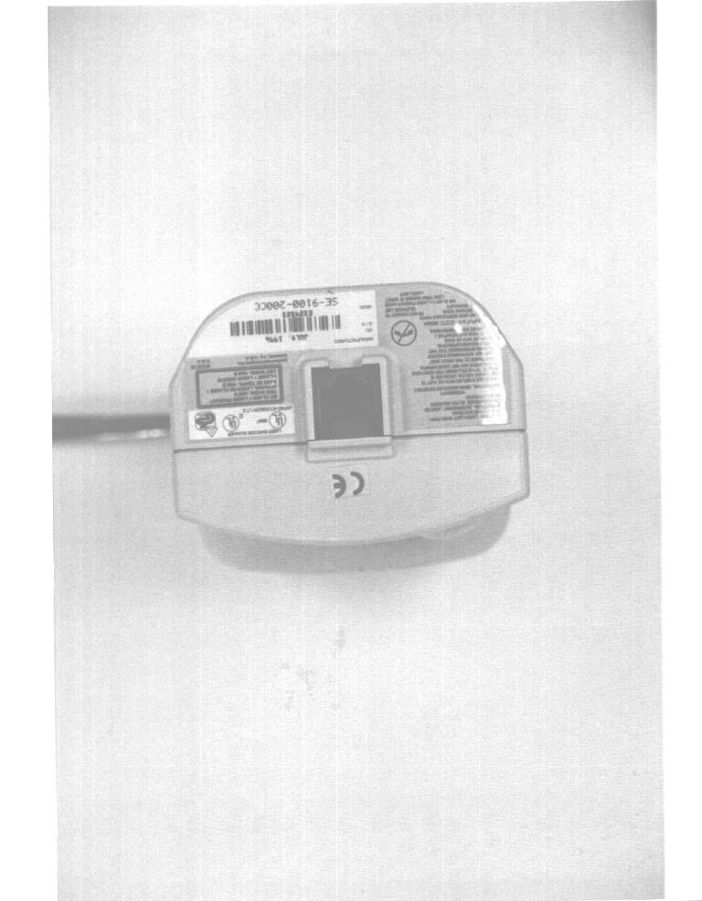
July 21, 1998 Federal Communications Commission Equipment Approval Services P.O. Box 358315 Pittsburgh, PA 15251-5315 Subject:Corrected information for FCC ID: ME9RFMODEMPCT 731 Confirmation Number: EA90121 To Whom It May Concern: I am electronically submitting a new set of product photographs for Continuum's PCT product. Photos from another product were accidentally mixed in with the photos originally submitted. The file name for the new photos is: pctfotos.pdf If there are any questions or problems please donβt hesitate to contact me at the number listed above, or by email, [email protected]. Sincerely, Chris Byleckie Technical Director
1249 birchwood drive Β· sunnyvale, California Β· United States
| # | Rule Parts | Frequency Range | Power Output |
|---|---|---|---|
| 1 | 15C | 906 MHz - 924 MHz | 331.00 mW |

Price Check Basestation Transmitter
Equipment Class
DSS - Part 15 Spread Spectrum Transmitter