MJYMPHRemote Control Transmitter
Applied Electronics Company
Click to zoom
Application Details
- Equipment Class
- DXX - Part 15 Low Power Communication Device Transmitter
- Date of Grant
- Mar 16, 2008
- Application Purpose
- Original Equipment
- Date of Application
- Mar 16, 2008
- Equipment Note
- Remote Control Transmitter
- Frequency Range
- 903.00000000 - 922.00000000
- Company
- Applied Electronics Company
- Country
- United States
Documents & Files
Document Text
Text extracted from the exhibit documents filed with the FCC. Open a document above to read the original.
Operational Description
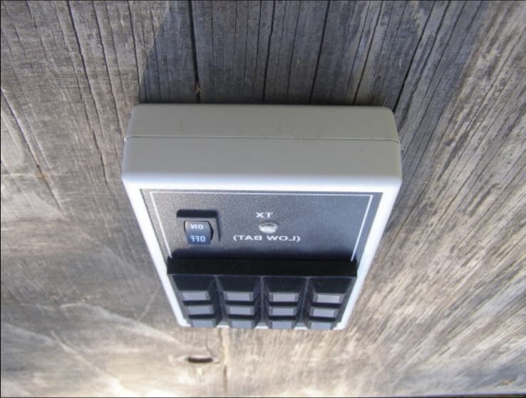
3132 Brown Street Boise, ID 83714 Phone (208) 344-2015 Fax (208) 344-2103 February 6, 2008 RE : Circuit Description for MP Series Transmitter Author : Darrell Downam Users interface with the transmitter through a keypad on the front of the transmitter. By pressing a button on the keypad a signal is sent to the microprocessor. That signal in turn is converted into a number that is compiled with an address code, that is pre-selected and set by jumpers. This compiled number is the sent serially at 2.4KB/s to the Linx Technologies transmitter module (tx module). This signal is then processed by the tx module and radiated at 921.3 Mhz at a level not to exceed FCC standards. The radiated signal is modulated at the 2.4KB/s rate in a Frequency Shift Modulation manor. The unit is battery powered and is controlled by an on/off switch. The battery voltage is obtained from 4 AA batteries that are converted to 5 VDC by a boost/buck DC-DC converter. This converter operates at 19Khz (approx.) and should not radiate any detrimental signals. Low battery conditions are indicated by a LED mounted in the case of the transmitter. The indicator will flash red when a button is pushed on the transmitter keypad. Under normal operation the LED will be a constant green indication. The following is an excerpt from the Linx Technologies datasheet for the employed TX module. The HP3 Series transmitter is a high-performance, multi-channel RF transmitter capable of transmitting both analog (FM) and digital (FSK) information. FM / FSK modulation offers significant advantages over AM or OOK modulation methods, including increased noise immunity and the receivers ability to capture in the presence of multiple signals. This is especially helpful in crowded bands, such as the one in which the HP3 operates. A precision 12.00MHz Voltage Controlled Crystal Oscillator (VCXO) serves as the frequency reference for the transmitter. Incoming data is filtered to limit the bandwidth, and then used to directly modulate the reference. Direct reference modulation inside the loop bandwidth provides fast start-up, while allowing a wide modulation bandwidth and near DC modulation capability. This also eliminates the need for code balancing. The modulated 12.00MHz reference frequency is applied to the Phase-Locked Loop (PLL). The PLL, combined with a 902 to 928MHz VCXO, forms a frequency synthesizer that can be programmed to oscillate at the desired transmit frequency. An on-board microcontroller manages the PLL programming and greatly simplifies user interface. The microcontroller reads the channel selection lines and programs the on-board synthesizer. This frees the designer from complex programming requirements and allows for manual or software channel selection. The microcontroller also monitors the status of the PLL and indicates when the transmitter is ready to transmit data by pulling the CTS line high. The PLL-locked carrier is amplified to increase the output power of the transmitter and to isolate the VCO from the antenna. The output of the buffer amplifier is connected to a filter network, which suppresses harmonic emissions. Finally, the signal reaches the single-ended antenna port, which is matched to 50 ohms to support commonly available antennas. Ap p li e d Ele c tr o n i c s Co mp a n y
Parts List/Tune Up Info
3132 Brown Street Boise, ID 83714 Phone (208) 344-2015 Fax (208) 344-2103 February 6, 2008 RE : Active Devices List for MP Series Transmitter Author : Darrell Downam 1. Linx Technologies TXM-900-HP3-PPO Transmitter Module a. Listed as same on schematic b. Converts data into RF Signal @ 921.3 Mhz. c. 2.4KB/s Data Rate FSK Modulation 2. Microchip PIC16F877A Microprocessor (U1 on board) a. Converts user keypad input into serial data. b. Outputs serial data to Linx Tech. module. 3. Analog Devices ADP1073A DC-DC Converter (U2 on board) a. Converts 3VDC battery voltage to 5VDC for circuitry. b. Operates @ 19Khz. Ap p li e d Ele c tr o n i c s Co mp a n y MPH Series Transmitter B.O.M. PartDesignatorQuantityPart #Distributor CaseCase1A9408357OKW LabelLabel1MP Series TX LabelScreenTek 12 Button KeypadKeypad184S-AC1-000Grayhill LED LensLens1LC10CLDigikey On/Off SwitchSwitch1EG1509Digikey BatteriesBatteries4LR06Energizer PC BoardPC Board1MP12TX-3Bare Board Group Transmitter ModuleTX11TXM-900-HP3-PPOLinx Technologies Antenna AssemblyANT11ANT-315-HETHLinx Technologies 44 pin PLCC SocketU1/Y11940-44-044-24-00000Digikey PIC16F877A MicrocontollerU11PIC16F877A-I/PMicrochip 4.7K ResistorR114.7KQBKDigikey 10K ResistorR2110KQBKDigikey 680 Ohm ResistorR31680QBKDigikey 680 Ohm ResistorR41680QBKDigikey 910K ResistorR51910KQBKDigikey 100K ResistorR61100KQBKDigikey 100K ResistorR71100KQBKDigikey 10K Resistor SMTR8110K SMT 0806Digikey LEDLED11LN11WP23Digikey 20 Mhz ResonatorX11490-1215Digikey TransistorsQ112N4403Digikey 47uf/10V CapacitorC11PCS2476CTDigikey 47uf/10V CapacitorC21PCS2476CTDigikey 1uf CapacitorsC31P4968Digikey 1uf CapacitorsC41P4968Digikey DC-DC Convertor ChipU21ADP1073N-5.0Digikey 1N5158 DiodeD111N5158Digikey Coil 15nH SMTL11PCD1374CTDigikey Coil 68nH SMTL21PCD1355CTDigikey 10K x 7 Resistor PackRP11770-81-10KDigikey 10K x 5 Resistor PackRP21770-61-10KDigikey Header Pins362663SDigikey Jumpers12A26244Digikey 3132 Brown Street Boise, ID 83714 Phone (208) 344-2015 Fax (208) 344-2103 February 6, 2008 RE : Tune-up Procedure for MP Series Transmitter Author : Darrell Downam 1. Make sure unit has fresh batteries. 2. Make sure antenna assembly is properly oriented. 3. Verify the transmitter field strength in test jig. 4. If output is within limits and spurious emissions are within specifications then unit passes. 5. If the unit does not meet specifications then adjustments to antenna assembly may be required, before retest. 6. If units radiated power is too high then the Linx Tech module may be replaced as there is no adjustment to this unit. 7. An 50 ohm pad may be added to ensure radiated power does not exceed limits. Ap p li e d Ele c tr o n i c s Co mp a n y
Schematics
Applied Electronics Co. 3132 Brown St. Boise ID 83714 Phone (208) 344-2015 Applied Electronics Co. 3132 Brown St. Boise ID 83714 Phone (208) 344-2015
Test Report
Flom Test Labs 3356 N. San Marcos Place, Suite 107 Chandler, Arizona 85225-7176 p0820004, d0820021 (866) 311-3268 phone, (480) 926-3598 fax Date: February 25, 2008 Federal Communications Commission Via: Electronic Filing Attention: Authorization & Evaluation Division Applicant: Applied Electronics Company Equipment: 900 MHz Remote Control Transmitter FCC ID: MJY-MPH FCC Rules: 15.249 Gentlemen: On behalf of the Applicant, enclosed please find Application Form 731, Engineering Test Report and all pertinent documentation, the whole for approval of the referenced equipment as shown. We trust the same is in order. Should you need any further information, kindly contact the writer who is authorized to act as agent. Sincerely yours, Hoosamuddin S. Bandukwala, Lab Director Flom Test Labs 3356 N. San Marcos Place, Suite 107 Chandler, Arizona 85225-7176 p0820004, d0820021 (866) 311-3268 phone, (480) 926-3598 fax List Of Exhibits (FCC Certification (Transmitters) - Revised 9/28/98) Applicant: Applied Electronics Company FCC ID: MJY-MPH By Applicant: 1. Letter Of Authorization 2. Identification Drawings Id Label Location Info Attestation Statement(S) Location of Compliance Statement 3. Documentation: 2.1033(B) (3) User Manual(S) (4) Operational Description (5) Block Diagram (5) Schematic Diagram (7) External Photographs Internal Photographs Parts List Active Devices By F.T.L. Inc. A. Testimonial & Statement of Certification B. Statement of Qualifications Flom Test Labs 3356 N. San Marcos Place, Suite 107 Chandler, Arizona 85225-7176 p0820004, d0820021 (866) 311-3268 phone, (480) 926-3598 fax Test Report for FCC ID: MJY-MPH Model: 900 MHz Remote Control Transmitter to Federal Communications Commission Rule Part(s)15.249 Date Of Report: February 25, 2008 On the Behalf of the Applicant: Applied Electronics Company 3132 Brown Street Boise, ID 83714 Attention of: wWilliam Sellers Phone: 208-344-2015 Fax: 208-344-2103 E-mail: [email protected] Supervised By: Hoosamuddin S. Bandukwala, Lab Director Flom Test Labs 3356 N. San Marcos Place, Suite 107 Chandler, Arizona 85225-7176 p0820004, d0820021 (866) 311-3268 phone, (480) 926-3598 fax The applicant has been cautioned as to the following: 15.21 Information to User. The users manual or instruction manual for an intentional radiator shall caution the user that changes or modifications not expressly approved by the party responsible for compliance could void the user's authority to operate the equipment. 15.27(a) Special Accessories. Equipment marketed to a consumer must be capable of complying with the necessary regulations in the configuration in which the equipment is marketed. Where special accessories, such as shielded cables and/or special connectors are required to enable an unintentional or intentional radiator to comply with the emission limits in this part, the equipment must be marketed with, i.e. shipped and sold with, those special accessories. However, in lieu of shipping or packaging the special accessories with the unintentional or intentional radiator, the responsible party may employ other methods of ensuring that the special accessories are provided to the consumer, without additional charge. Information detailing any alternative method used to supply the special accessories for a grant of equipment authorization or retained in the verification records, as appropriate. The party responsible for the equipment, as detailed in § 2.909 of this chapter, shall ensure that these special accessories are provided with the equipment. The instruction manual for such devices shall include appropriate instructions on the first page of text concerned with the installation of the device that these special accessories must be used with the device. It is the responsibility of the user to use the needed special accessories supplied with the equipment. Flom Test Labs 3356 N. San Marcos Place, Suite 107 Chandler, Arizona 85225-7176 p0820004, d0820021 (866) 311-3268 phone, (480) 926-3598 fax Testimonial And Statement Of Certification This is to certify that: 1. That the application was prepared either by, or under the direct supervision of, the undersigned. 2. That the technical data supplied with the application was taken under my direction and supervision. 3. That the data was obtained on representative units, randomly selected. 4. That, to the best of my knowledge and belief, the facts set forth in the application and accompanying technical data are true and correct. Certifying Engineer: Hoosamuddin S. Bandukwala, Lab Director Flom Test Labs 3356 N. San Marcos Place, Suite 107 Chandler, Arizona 85225-7176 p0820004, d0820021 (866) 311-3268 phone, (480) 926-3598 fax Table Of Contents Rule Description Page Test Report 1 2.1033(c) General Information Required 2 Standard Test Conditions and Engineering Practices 4 Test Results Summary 5 15.249(a) Fundamental Field Strength 6 15.249(d) Radiated Spurious Emissions 7 . Test Equipment Utilized 8 Flom Test Labs 3356 N. San Marcos Place, Suite 107 Chandler, Arizona 85225-7176 p0820004, d0820021 (866) 311-3268 phone, (480) 926-3598 fax Page 1 of 9 Required information per ISO 17025-2005, paragraph 5.10.2: a) Test Report b) Laboratory: (FCC: 31040/SIT) (Canada: IC 2044A-1) Flom Test Lab, Inc. 3356 N. San Marcos Place, Suite 107 Chandler, AZ 85225 c) Report Number: d0820021 d) Client: Applied Electronics Company e) Identification: 900 MHz RC Transmitter Description: Remote Control Transmitter f) EUT Condition: Not required unless specified in individual tests. g) Report Date: February 25, 2008 EUT Received: h, j, k): As indicated in individual tests. i) Sampling method: No sampling procedure used. l) Uncertainty: In accordance with FTL internal quality manual. m) Supervised by: Hoosamuddin S. Bandukwala, Lab Director n) Results: The results presented in this report relate only to the item tested. o) Reproduction: This report must not be reproduced, except in full, without written permission from this laboratory. Flo…
Text truncated - open the document above for the full version.
Test Report
Annex 1 902 MHz Band Edge Compliance 928 MHz Band Edge Compliance
Contact Information
Applicant
William Sellers(President)
Technical Contact
Flom Test LabHoosamuddin Bandukwala
[email protected]480-926-3100
3356 S. San Marcos Pl. · Chandler, Arizona · United States
Test Firm
Compliance Testing, LLCMichael Schafer
Technical Specifications
| # | Rule Parts | Frequency Range | Power Output |
|---|---|---|---|
| 1 | 15C | 903 MHz - 922 MHz | - |
Other Applications from Applied Electronics Company
MJYMPJ
Mar 20, 2008Hand Held Transmitter
Equipment Class
DSC - Part 15 Security/Remote Control TransmitterMJY-ICRB
Jan 23, 1996CXX - Communications Rcvr for use w/ licensed Tx and CBs
Equipment Class
CXX - Communications Rcvr for use w/ licensed Tx and CBs