MKDAR247SCANNING RECEIVER PART OF TRANSCEIVER
ADI Communications Corporation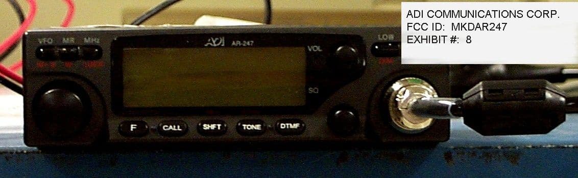
Click to zoom
Application Details
- Equipment Class
- CSR - Scanning Receiver
- Date of Grant
- Nov 03, 1999
- Application Purpose
- Original Equipment
- Date of Application
- Aug 18, 1999
- Equipment Note
- SCANNING RECEIVER PART OF TRANSCEIVER
- Frequency Range
- 215.00000000 - 229.99500000
- Country
- Taiwan
Documents & Files
Document Text
Text extracted from the exhibit documents filed with the FCC. Open a document above to read the original.
Attestation Statements
STATEMENT October 12, 1999 Federal Communications Commission Authorization and Evaluation Division 7435 Oakland Mills Road Columbia, MD 21046 To whom it may concern: We, ADI Communications Corp., hereby assured that our product AR-247 cannot be altered to receive cellular band by any modifications ( tuning, control, filtering , change parts or modify circuit ). That is because following reason: 1. The oscillate frequency of VCO is 240MHz Max. only. 2. The working frequency of synthesizer “MB1504” that can not over 600MHz. Sincerely, ADI Communications Corp. W.J.Tso ADI Communications Corp. No.193,Sec. 1,Chungching Road, Taya,Taichung,Taiwan 428,R.O.C. Tel: 886-4-5600511 Fax: 886-4-5601827
Attestation Statements
STATEMENT October 27, 1999 Federal Communications Commission Authorization and Evaluation Division 7435 Oakland Mills Road Columbia, MD 21046 To whom it may concern: We, ADI Communications Corp., hereby assured that our product AR-247 cannot be altered to receive cellular band by any modifications ( tuning, control, filtering , change parts or modify circuit ). That is because following reason: 1. ADI/AR247 FCC/INQ a. The design features is based on the following: - The VCO fixing the frequency range from 180- 230MHz so that it can not to receive the CELLULAR BAND FOR UP TO 800MHz. - The frequency of synthesizer(MB1504) using range are below the 520MHz, it can't be to modified up to 800 MHz. - All the design features inside using " helical filter" ( L8, L9 ) and also fix for 215-230 MHz ranges it can't be modified too. - The receiving image rejection spec. are > 80 dB. So that it can not to receive the CELLULAR BAND FOR UP TO 800MHz. - The transmit frequency range fixing from 222- 224.995MHz so that it can not to receive the CELLULAR BAND FOR UP TO 800MHz. b. The design step taken as follow ; - Basically AR-247 is a superheterodyne receiver , it can only be receive signal range from 215 ~ 230 MHz. also the VCO range are 184.5 ~ 199.15 MHz in between , there are mixing a fixing IF frequency 30.85 MHz to working on it so this is much lower then the receive range. - The receiving range use "band pass filter" to attenuate fixing helical filter(L8,L9) range from 215- 230 MHz, with limit to up to 60dB so it can not to receive CELLULAR BAND. ADI Communications Corp. No.193,Sec. 1,Chungching Road, Taya,Taichung,Taiwan 428,R.O.C. Tel: 886-4-5600511 Fax: 886-4-5601827 Sincerely, ADI Communications Corp. W.J.Tso
Schematics
1 2 3 4 5 6 7 8 9 10 11 12 12 11 10 9 8 7 6 5 4 3 2 1 Ti t l e Number Revi si Si ze A1 Date: 17-Aug-1999 Sheet o f Fi l e: D: \WELLO\SCH\A R Drawn B y 1234567 MOD10V 8V DCS CV GND O/ P 65 48 123456 9 8V I N 5V 2341 XIXO 765 LOCKDATA CK STB MID POWER 7 OUT 8 7 HI POWER ANT. CABLE C1 15p(DI P) C3 1p C2 0. 5p R110K R210K C4 1000p C81000p C5 15p(DI P) C6 0. 5p C71p C11 22p(DIP) C12 39p(DI P) D4 MI 3 08 C162p C19 1000p C21 1000p R6 33K R447 C17 1000p R7 100 C18100p C222p C9 1000p R16 47 R24 47 C23 1000p C31 1000p C102 0.01u C2639p R25 1K R261K L12 IF=30.85MHz + C103 47u/ 25V R98 330K Q27 2SC2712Y R94 1.8K R921. 8K R93 10K R9610K R95 10K Q24 2SB1119S (BBS) Q26 2SC2712Y XF 2 30. 85MHz R28 1. 2K XF 1 30. 85MHz Q28 2SC2712Y R99 22K + C105 47u/ 25V C1040.01u Q23 2SB1119S (BBS) R9722K R100 47K C38 1000p C36 1000p Q8 2SC2714Y R32 100 R311K R30330K R29470 R33330K L1410u R35150 X1 30.395MHz C4018p C421000p CD1 CDBM455C16 213456 CN2 R3927K R38 27K R40330 + C115 47u 25V C118 0.01u + C117 47u/ 25V J1 C1190. 1u R111 1 POWER I NDC 13.8V SPEAKER C112 0.022u R110220 + C114 10u50V + C113 47u 25V R102 1K C109 1u R103 1K R1044.7K + C1104. 7u50V R10522K + C90 1000u 25V C91 0.01u C98 0. 01u + C97 47u 25V I/P 1 O/ P 3 2 U2 MC 7 8 0 8 C T C96 0. 01u R814701/ 2W R8010K Q21 2SB1302S (BJS) R10627KR10747K R108 33K R831K I/ P 1 O/ P 3 2 U3NJM78L05UA R904. 7K R86 22 1 2 3 4 5 6 7 8 9 10 11 12 13 CN4 Q17 2SC2712Y + C76 220u 10V C750. 01u R66 1. 5K + C77220u10V L161u R614. 7K C72 1000p R62 2.2K R60100 Q16 2SC2759 (U23) C70 5p C71 1000p GND 1 O/ P 2 NC 3 NC 4 NC 5 NC 6 I/ P 7 NC 8 U1 LA5010M R47 0 C15 5p (MICA) L150. 5*3*9. 5T R411201/ 2W C501000p C59 1000p R59 2. 2K C7310p R1502 1K C1507 1p L1504 1u C1509 15p L15050. 33u C1511 0. 5p C1510 15p R1506 47 C15141000p R1510100 R1508 4. 7K Q1502 2SC3120 (HB) R1509 10K C79 1000p R1303 1K Q1301 2SC4116 (GR) R1301100K C13021000p R13053. 3K C13030. 033u C1304 27p R1307 180K R1308 33K R1310 47K R1312220K C13050. 1u + C13061u/16V R1311470K R1309560K R1316 0 C13083300p R1315 82K R1314 82K R1313 82K C13101000p R1306 0 C1311 100p R73100 C87 0. 01u R761K C88 1000p R7815K R74100K R72 4. 7K C82 1000p R6910K R7010K R6727KVR450K + C1404 2. 2u10V R1409 10K C14091000p C1407 1p Q1402 2SC2714Y L14011u C1408 10p C14061000p R1402 100 C1412 0. 022u + C1411 4.7u/10V C1001000p R1410 47K R140110K C14031000p C14050.01u R1413 3.3K C14100. 022u R1414 1. 8K Q14042SC4116BL R1405 18K VC310p C61 1000p 1 2 3 4 5 6 7 8 9 10 11 12 13 CN3 C108 4p X2 12. 8MHz D3 MI 4 07 R491K L1506150n MURATA C130982p R6822K Q182SD1757K C81 0.027u R1403 220K R1411 10K R141522K D12 GP30A C35 6p C30 1000p R22220 C44 1000p Q29 2SD1757K R36100K R37 100K C111 470p R109 47K C99 0.01u + C101 47u/25V Q9 2SJ106 (VG) R1407 18K R1406 18K C56 1u VR210K R50100K + C116 470u/ 10V R894. 7K C890. 1u C46 1u Q1 3SK241 VR310K R521. 5K C1307 560p R1304 100 C1301 0. 1u R1302 22K + C83 2.2u/10V C84 1000p C80 1u R884. 7K R874.7K Q15 2SD1406(Y) D11 1SS181(A3) C62 1000P R85 22 C93 0.01u R45 22 1/ 2W R65 22 R63 100 C78 0.01u R1408 10K R1412 100 C1502 1000P C1506 1p R1501 470 L15021u C1512 10P R1504 100 C15011000p Q15012SK508(K52) L15035CBM C10 10p(DI P) R5 100K D1503 1SV231 D15021SV231 Q6 3SK241 S-METER DEVIATION MAIN BOARD XI 1 XO 2 VP 3 VCC 4 DO 5 GND 6 LD 7 FIN 8 CK 9 DT 10 LE 11 FC 12 FR 13 FP 14 $P 15 $R 16 U1401MB1 5 04 D1403DA204K D1402DA204K Q1403 2SA1235F A1A5 VCO D14018.2V ANTENNA D1 MA 7 1 6 D2 MA 7 1 6 IF1 I/P 1 GN D 2 XI 3 XO 4 MO 5 8V 6 AF 7 CD 8 SC 9 SQ 10 SM 11 DET 12 NAG 13 RD 14 AF O/P 15 GN D 16 A1A1 C4168p CF1 CFWM455F + C45 47u/ 25V VR1100K OUT 1 CV 2 GN D 3 GN D 4 NC 5 GN D 6 GN D 7 8V 8 GN D 9 GN D 10 GN D 11 IN 12 VHF A1A7 D141SS184 D15 1SS184 1 3 4 5 Q12 FMW1 R531.2K R5510K R5410K R561. 5K R581K R57 3. 3K Q14 2SA1162 /SY C67 1000p C64 4700p C664700p + C63 1u/ 16V C651000p 2 1 3 4 5 Q13FMW1 2 C690. 1u Q10 DTC124EK(25) Q11 DTC124EK(25) C941000p D16IMN10 A1A4 PLL DTMF NC GND GND GND GND A1A3 MIC AMP (BC217I301Q) C860. 1u Q19 2SC2712Y C850. 039u R7510K R774.7K CN1 I/P 1 BYP ASS 2 FB 3 GN D 4 GN D 5 O/P 6 BOOT 7 VD D 8 U5UPC1241H STB* 1 DATA 2 CLOCK 3 Q1 4 Q2 5 Q3 6 Q4 7 GND 8 QS 9 QS* 10 Q8 11 Q7 12 Q6 13 Q5 14 EN 15 VDD 16 U4BU4094BCFV D13 UDZ16B R7947K EXT. SP. MO N ITON ERDMI CGNDGNDA R- 2 B BC27 8 WE L LC7582 LCD HOLDER LCD BOARD C3020. 039U R303 100 1/ 8W S31 32 S30 31 S29 30 S28 29 S27 28 S26 27 S25 26 S24 25 24 S23 23 S22 22 S21 21 S20 20 S19 19 S18 18 S17 17 S3 2 33 S3 3 34 S3 4 35 S3 5 36 S3 6 37 S3 7 38 S3 8 39 S3 9 40 S4 0 41 S4 1 42 S4 2 43 S4 3 44 S4 4 45 S4 5 46 S4 6 47 S4 7 48 S48 49 S49 50 S50 51 S51 52 S52 53 S53 54 OSC 55 VD D 56 INH 57 VL O D 58 VSS 59 CE 60 CLK 61 DATE 62 COM2 63 COM1 64 S1 1 S2 2 S3 3 S4 4 S5 5 S6 6 S7 7 S8 8 S9 9 S1 0 10 S1 1 11 S1 2 12 S1 3 13 S1 4 14 S1 5 15 S1 6 16 U301 LC7582 R3022. 7K1/ 8W C303 1U C304 1U R310820K C301680P R30139K1/ 8W S4 7 1 S4 6 2 S4 5 3 S4 4 4 S4 2 5 S4 1 6 S4 3 7 S4 0 8 S3 9 9 S3 8 10 S3 1 11 S2 9 13 S3 0 12 S2 8 14 S2 7 15 S2 6 16 S2 5 17 S2 4 18 S3 7 19 S2 3 20 S2 2 21 S2 1 22 S2 0 23 S3 6 24 S1 9 25 S1 8 26 S1 7 27 S1 6 28 S3 5 29 S1 5 30 S1 4 31 S1 3 32 S1 2 33 S3 4 34 S3 3 35 S1 1 36 S1 0 37 S9 38 S8 39 S7 40 S6 41 S3 2 42 S5 43 S4 44 S3 45 S2 46 S1 47 COM1 48 COM2 49 LCD PL1LAMP PL2 LAMP PL3LAMP PL4 LAMP R309271W R308271W R307 271W R306271W D301LFB01 R3041001/ 2W R3051001/ 2W PL5LAMP 1 2 3 4 5 6 7 8 9 CN301 C491u C107 1u C106 1u C7410p PL6LED TO DTMF BO A Q20 DTC144EK D5 MI 308 R3 0 VC110p VC2 6p L8 HELI CAL FI LTER Q5 2SK937-Y5 L9 HELI CAL FILTER C27 1000p R1722 R19 0 L1147n C3222p D8 1SV128 C33 1000p L1018n C2947p R20 47 R2122K C28 2p L7 47n L6 39n L5 0. 65* 3*5T L3 0.65*3*2. 5T L2 0.65*3*2. 5T L1 0.5*3*9. 5T C24 1000p R10 0 R15 0 TP1 18P R23 X L131u C37 1000p I/P 1 VC 1 2 VC 2 3 O/P 4 U6M6 8 7 2 9 C57 1000p + C5310u50V C52 1000p C511000p D10 1SV128 C681000p C60 1000p R64 0 + C92 47u 25V R84 10 R1507 47 R1503 68K C1503 100p D15011SV231 L15011u DATACLOCKLCD STB5VGNDLAMPNCDIMDIM GND 13.8V 5V 13.6V 8V BZ VOL2 VOL1 DCS TONE ME MIC GND GND OV P STB1 LED STB2 CL K DA TA D…
Text truncated - open the document above for the full version.
Test Report
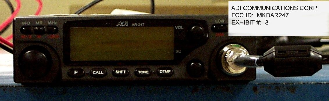
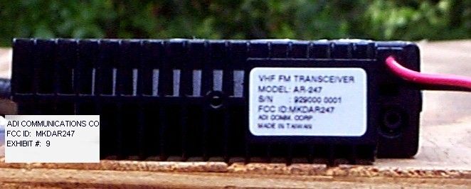
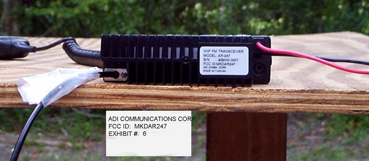
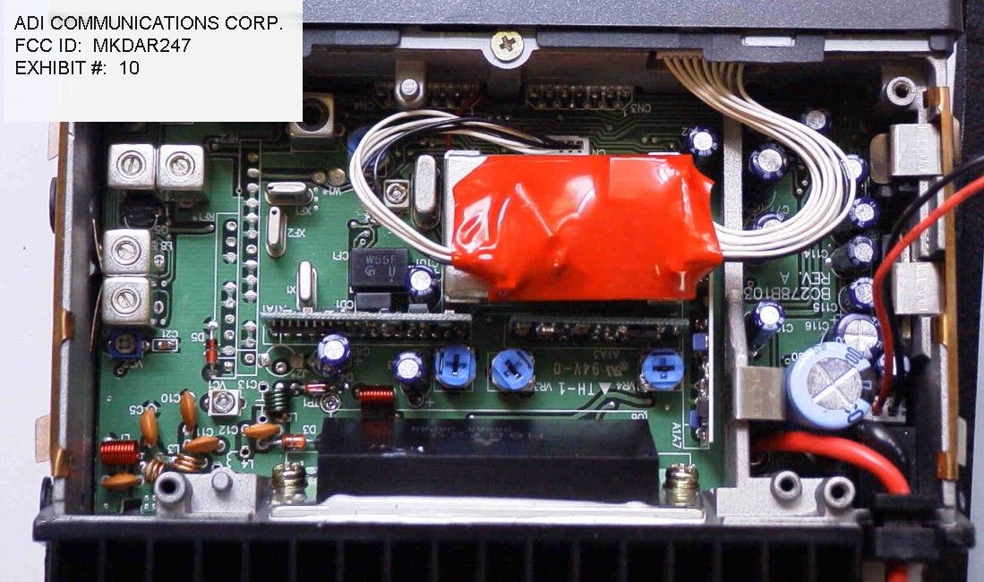
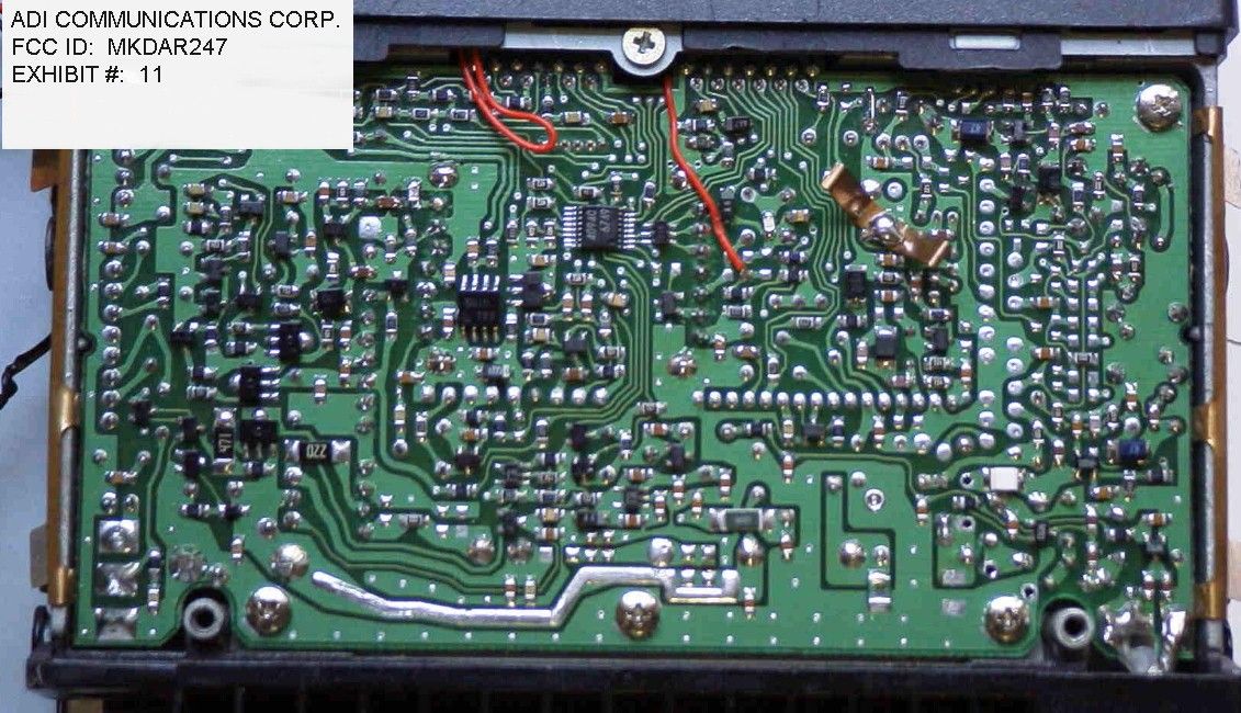
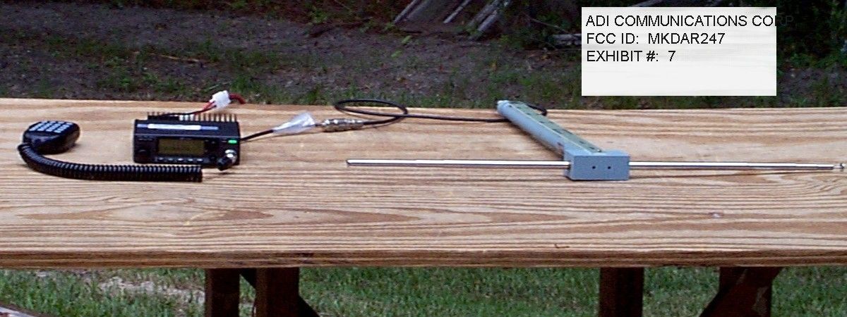
TABLE OF CONTENTS LIST APPLICANT: ADI COMMUNICATIONS CORPORATION FCC ID: MKDAR247 TEST REPORT CONTAINING: PAGE 1......TEST PROCEDURE PAGE 2......TEST PROCEDURE & CIRCUIT DESCRIPTION PAGE 3......RADIATION INTERFERENCE TEST DATA EXHIBITS CONTAINING: EXHIBIT 1............POWER OF ATTORNEY LETTER EXHIBIT 2............STATEMENT PER 15.121(a) EXHIBIT 3............BLOCK DIAGRAMS EXHIBIT 4............SCHEMATICS EXHIBIT 5A-5UU.......INSTRUCTION MANUAL EXHIBIT 6............SAMPLE OF FCC ID LABEL AND SKETCH OF LOCATION EXHIBIT 7............TEST SETUP PHOTOGRPAH EXHIBIT 8............EXTERNAL PHOTO - FRONT SIDE EXHIBIT 9...........EXTERNAL PHOTO - BACK SIDE EXHIBIT 10...........INTERNAL PHOTO - COMPONENT SIDE EXHIBIT 11...........INTERNAL PHOTO - COPPER SIDE APPLICANT: ADI COMMUNICATIONS CORPORATION FCC ID: MKDAR247 REPORT #: F:\CUS\A\ADI\ADI353T9\ADI353T9RPT PAGE: TABLE OF CONTENTS LIST APPLICANT: ADI COMMUNICATIONS CORPORATION FCC ID: MKDAR247 TEST EQUIPMENT LIST 1. Spectrum Analyzer: Hewlett Packard 8566B - Opt 462, w/ preselector 85685A, & Quasi-Peak Adapter HP 8565OA, & HP 8449B - OPT H02 Cal. 7/6/99 2. Signal Generator, Hewlett Packard 8640B, cal. 10/1/98 3. Signal Generator, HP 8614A Serial No.2015A07428 cal. 5/27/99 3. Eaton Biconnical Antenna Model 94455-1 20-200 MHz Serial No. 0997 Cal. 10/30/98 4. Electro-Metric Dipole Kit, 20-1000 MHz, Model TDA-30 10/31/98 5. Electro-Metric Horn 1-18 GHz, Model RGA-180, Cal. 10/30/98 6. Electro-Metric Antennas Model TDA-30/1-4,Cal. 10/15/98 7. Electro-Metric Line Impedance Stabilization Network Model No. EM-7821, Serial No. 101; 100KHz-30MHz 50uH. Cal.11/19/98 8. Electro-Metric Line Impedance Stabilization Network Model No. EM-7820, Serial No. 2682; 10KHz-30MHz 50uH. Cal. 11/19/98 9. Special low loss cable was used above 1 GHz 10. Tenney Temperature Chamber TEST PROCEDURE GENERAL: This report shall NOT be reproduced except in full without the written approval of TIMCO ENGINEERING, INC. RADIATION INTERFERENCE: The test procedure used was ANSI STANDARD C63.4-1992 using a HEWLETT PACKARD spectrum analyzer with a prese- lector. The bandwidth of the spectrum analyzer was 100 kHz with an appropriate sweep speed. The analyzer was calibrated in dB above a microvolt at the output of the antenna. The resolution bandwidth was 100KHz and the video bandwidth was 300KHz. The ambient temperature of the UUT was 80oC with a humidity of 76%. FORMULA OF CONVERSION FACTORS: The Field Strength at 3m was estab- lished by adding the meter reading of the spectrum analyzer (which is set to read in units of dBuV) to the antenna correction factor sup- plied by the antenna manufacturer. The antenna correction factors are stated in terms of dB. The gain of the Preselector was accounted for in the Spectrum Analyzer Meter Reading. Example: Freq (MHz) METER READING + ACF = FS 33 20 dBuV + 10.36 dB = 30.36 dBuV/m @ 3m POWER LINE CONDUCTED INTERFERENCE: The procedure used was ANSI STAN- DARD C63.4-1992 using a 50uH LISN. Both lines were observed. The bandwidth of the spectrum analyzer was 10kHz with an appro- priate sweep speed. The ambient temperature of the UUT was 80oC with a humidity of 76%. APPLICANT: ADI COMMUNICATIONS CORPORATION FCC ID: MKDAR247 REPORT #: F:\CUS\A\ADI\ADI353T9\ADI353T9RPT PAGE #: 1 TEST PROCEDURES CONTINUED APPLICANT: ADI COMMUNICATIONS CORPORATION FCC ID MKDAR247 ANSI STANDARD C63.4-1992 10.1.7 MEASUREMENT PROCEDURES: The unit under test was placed on a table 80 cm high and with dimensions of 1m by 1.5m. The table used for radiated measurements is capable of continuous rotation. When an emission was found, the table was rotated to produce the maximum signal strength. At this point, the antenna was raised and lowered from 1m to 4m. The antenna was placed in both the horizontal and vertical planes. The situation was similar for the conducted measurement except that the table did not rotate. The EUT was setup as described in ANSIC63.4-1992 with the EUT 40 cm from the vertical ground wall. CIRCUIT DESCRIPTION: In the receive mode the signal comes in on the receive antenna to the double tuned circuit to the super-regenerative detector Q-3, where the audio is detected. From Q-3 the audio goes to the volume resistor R15 to the input to the three(3) stage audio amplification, Q1, Q4 & Q5. Q5 drives the audio output transform- er T3 which is connected to the speaker. ANTENNA AND GROUND CIRCUITRY This unit makes use of a external 5 inch antenna. The antenna is inductively coupled. This unit is powered from a 9.0V battery. No ground connection is provided. The unit relies on the ground tract of the printed circuit board. APPLICANT: ADI COMMUNICATIONS CORPORATION FCC ID: MKDAR247 REPORT #: F:\CUS\A\ADI\ADI353T9\ADI353T9RPT PAGE #: 2 APPLICANT: ADI COMMUNICATIONS CORPORATION FCC ID: MKDAR247 NAME OF TEST: RADIATION INTERFERENCE RULES PART NUMBER: 15.109 REQUIREMENTS: 30 to 80 MHz: 40.0 dBuV/M @ 3 METERS 88 to 216 MHz: 43.5 dBuV/M 216 to 960 MHz: 46.0 dBuV/M ABOVE 960 MHz: 54.0 dBuV/M TEST RESULTS: A search was made of the spectrum from 30 to 1000 MHz and the measurements indicate that the unit DOES meet the FCC requirements. TEST DATA: ANTENNA TUNED EMISSION METER READING COAX CORRECTION FIELD FREQ FREQUENCY AT 3 METERS LOSS FACTOR STRENGTH MARGIN MHz MHz dBuV dB dB dBuV/m@3m dB ANT 215.00 184.14 23.00 0.90 14.30 38.20 5.30 H 215.00 368.32 15.60 1.40 16.08 33.08 12.92 H 215.00 552.50 10.00 1.60 19.72 31.32 14.68 H 215.00 736.60 11.70 2.00 21.79 35.49 10.51 V 222.00 191.20 18.90 0.90 13.55 33.35 10.15 H 222.00 382.30 16.70 1.40 16.49 34.59 11.41 H 229.99 199.14 16.90 0.90 12.69 30.49 13.01 H 229.99 398.30 18.00 1.40 16.95 36.35 9.65 H 229.99 597.40 10.40 1.60 20.08 32.08 13.92 H SAMPLE CALCULATION: FSdBuV/m = MR(dBuV) + ACFdB. TEST PROCEDURE: ANSI STANDARD C63.4-1992 using a Hewlett Packard Model 8566B spectrum analyzer, a Hewlett Packard Model 85685A Preselector, a Hewlett Packard Model 85650A Quasi-Peak adapter, an Electro-Metric Dipole Kit, and an Eaton Model 94455-1 Bicon…
Text truncated - open the document above for the full version.
Test Report
APPLICANT: ADI COMMUNICATIONS CORPORATION FCC ID: MKDAR247 NAME OF TEST: 38dB REJECTION RATIO RULES PART NUMBER: 15.121(b) REQUIREMENTS: 38dB REJECTION RATIO TO SENSITIVITY OF OF THE RECEIVER. TEST SET-UP /---------\ /----------\ /---------\ |RF SIGNAL| |RECEIVER | | AUDIO | |GENERATOR|---|UNDER TEST|---| LOAD | \---------/ \----------/ \---------/ /----------\ |DISTORTION| | METER | \----------/ TEST PROCEDURE: The reference sensitivity was measured in accor- dance with TIA/EIA-603; a. Equipment connected as illustrated b. A standard signal was applied to the receiver input terminals. c. Receiver output audio output was adjusted for rated output. d. The RF Signal generator was adjusted to the lowest level to produce a 12dB SINAD without the audio output dropping more than 3dB. e. This was done across the different bands to establish a reference level. The reference taken was the highest sensitivity in all of the bands. f. The output of the signal generator was then adjusted to a level of 50dB above the reference level. g. The receiver was then set to the low end of the 1st band and the signal generator was tuned over to frequency range of 824-849MHz and 869-894MHz in search of a response. h. Step g was repeated at the middle, and top on the 1st band then repeated in the same way for all of the other bands. TEST RESULTS: The UUT does meet the 38dB REJECTION RATIO. PERFORMED BY: S. S. SANDERS DATE: AUGUST 13, 1999 APPLICANT: ADI COMMUNICATIONS CORPORATION FCC ID: MKDAR247 REPORT #: F:\CUS\A\ADI\ADI353T9\ADI353T9RPT PAGE #: 4
Test Report
TIMCO ENGINEERING INC. PO Box 370 849 SR 45 Newberry, Florida 32669 Ph. 352.472.5500 Fax. 352.331.8840 [email protected] 10/28/99 TO: JOE DICHOSO FCC Subject: ADI COMMUNICATIONS CORPORATION FCCID: MKDAR247 REFERENCE: EA95189 I tried to call you because I had some problems understanding your email. Anyway here is what I think you want me to do. APPLICANT: ADI Communications Corporation FCC ID: MKDAR247 NAME OF TEST: 38dB REJECTION RATIO RULES PART NUMBER: 15.121(b) REQUIREMENTS: 38dB REJECTION RATIO TO SENSITIVITY OF THE RECEIVER. TEST SET-UP /---------\ /----------\ /---------\ |RF SIGNAL| |RECEIVER | | AUDIO | |GENERATOR|---|UNDER TEST|---| LOAD | \---------/ \----------/ \---------/ /----------\ |DISTORTION| | METER | \----------/ TEST PROCEDURE: The reference sensitivity was measured in accor- dance with TIA/EIA-603; a. Equipment connected as illustrated b. A standard signal was applied to the receiver input terminals. c. Receiver output audio output was adjusted for rated output. d. The RF Signal generator was adjusted to the lowest level to produce a 12dB SINAD without the audio output dropping more than 3dB. Make note of sensitivity level. e. This was done across the different bands to establish a reference level. The reference taken was the highest sensitivity in all of the bands. f. The output of the signal generator was then adjusted to a level of 60dB above the reference level. 10/28/99 PAGE2OF2 g. With the level set 60dB the level measured in step d, h. Set squelch on receiver to threshold, The signal level required to open the squelch must be lower than the level measured in step d. i. Cause the receiver to scan or step-it through its complete range of frequencies. j. If receiver stops or unsquelches on any frequency, record the frequency and then adjust the level until a 12dB SINAD is produced. This level must be greater than 38dB. k. Repeat steps f thorugh j for frequencies 836.0, 848.5, 869.1, 881.0, & 893.5MHz. TEST RESULTS: The UUT meet the 38dB REJECTION RATIO. PERFORMED BY: S. S. SANDERS DATE: OCTOBER 27, 1999 I stepped the frequencies on the receiver through its full range of frequencies in 10KHz steps, which is the smallest steps that it will make, I think. Please let me know if this is okay. Thanks for your help. BEST REGARDS, Sid Sanders CHECK OUT OUR WEBSITE @www.timcoengr.com
Test Report
TIMCO ENGINEERING INC. PO Box 370 849 SR 45 Newberry, Florida 32669 Ph. 352.472.5500 Fax. 352.331.8840 [email protected] 11/4/99 TO: JOE DICHOSO FCC Subject: ADI COMMUNICATIONS CORPORATION FCCID: MKDAR247 REFERENCE: EA95189 APPLICANT: ADI Communications Corporation FCC ID: MKDAR247 NAME OF TEST: 38dB REJECTION RATIO RULES PART NUMBER: 15.121(b) REQUIREMENTS: 38dB REJECTION RATIO TO SENSITIVITY OF THE RECEIVER. TEST SET-UP /---------\ /----------\ /---------\ |RF SIGNAL| |RECEIVER | | AUDIO | |GENERATOR|---|UNDER TEST|---| LOAD | \---------/ \----------/ \---------/ /----------\ |DISTORTION| | METER | \----------/ TEST PROCEDURE: The reference sensitivity was measured in accor- dance with TIA/EIA-603; a. Equipment connected as illustrated b. A standard signal was applied to the receiver input terminals. c. Receiver output audio output was adjusted for rated output. d. The RF Signal generator was adjusted to the lowest level to produce a 12dB SINAD without the audio output dropping more than 3dB. Make note of sensitivity level. e. This was done across the different bands to establish a reference level. The reference taken was the worse case sensitiv- ity. f. The output of the signal generator was then adjusted to a level of 60dB above the reference level at a frequency of 824.5MHz. g. With the level set 60dB above the level measured in step e, PAGE2OF2 h. Set squelch on receiver to threshold, The signal level required to open the squelch must be lower than the level measured in step d. i. Cause the receiver to scan or step-it through its complete range of frequencies. j. If receiver stops or unsquelches on any frequency, record the frequency and then adjust the level until a 12dB SINAD is produced. This level must be greater than 38dB above the level in step e. k. Repeat steps f thorugh j for frequencies 836.0, 848.5, 869.1, 881.0, & 893.5MHz. TEST RESULTS: The UUT meet the 38dB REJECTION RATIO. PERFORMED BY: S. S. SANDERS DATE: &DATE& I stepped the frequencies on the receiver through its full range of frequencies in 10KHz steps, which is the smallest steps that it will make, I think. Please let me know if this is okay. Thanks for your help. BEST REGARDS, Sid Sanders
Contact Information
Applicant
W J Tso(QA Supervisor)
Technical Contact
TIMCO ENGINEERING, INC.S.S. SANDERS
[email protected]888-472-2424
P.O. BOX 370 · NEWBERRY, Florida · United States
Non-Technical Contact
TIMCO ENGINEERING, INC.SHARON A HOFFMAN
[email protected]888-472-2424
Test Firm
Timco Engineering, Inc.Sid Sanders
Technical Specifications
| # | Rule Parts | Frequency Range | Power Output |
|---|---|---|---|
| 1 | 15B | 215 MHz - 229.995 MHz | - |
Other Applications from ADI Communications Corporation
MKDAT401
Sep 16, 1999Scanning Receiver
Equipment Class
CSR - Scanning Receiver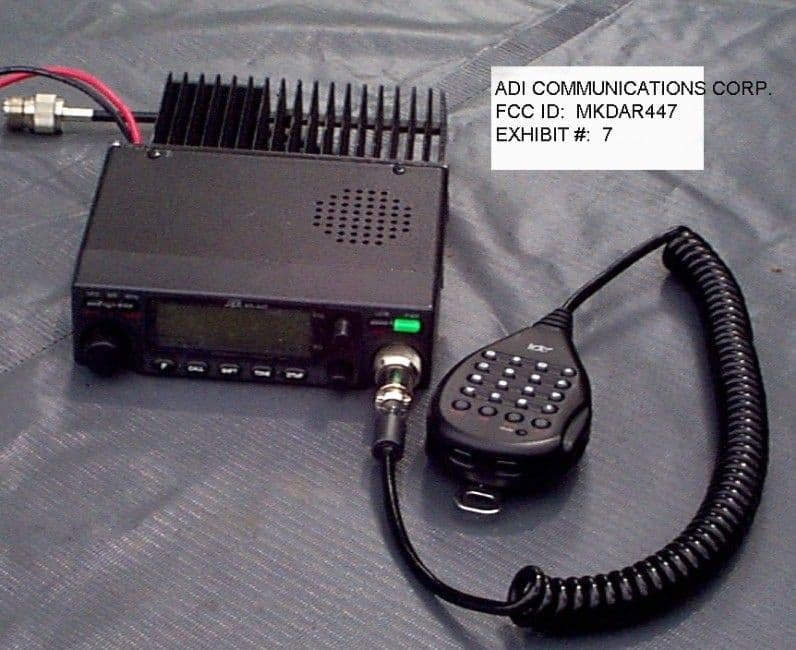
MKDAR447
Jun 21, 1999CSR - Scanning Receiver
Equipment Class
CSR - Scanning Receiver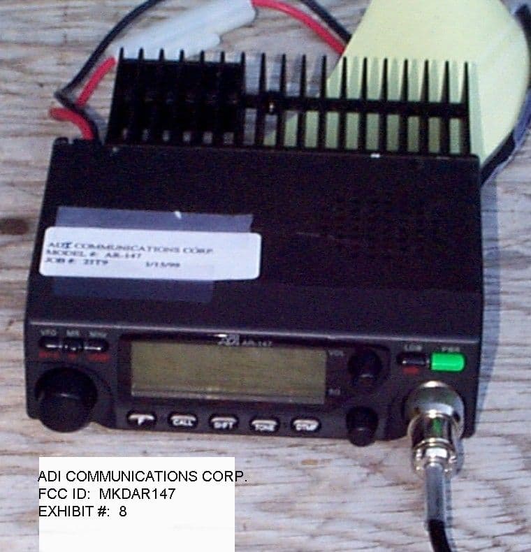
MKDAR147
May 10, 1999MOBILE TRANSCEIVER
Equipment Class
CSR - Scanning ReceiverMKDAT201
Sep 11, 1996CXX - Communications Rcvr for use w/ licensed Tx and CBs
Equipment Class
CXX - Communications Rcvr for use w/ licensed Tx and CBsMKDAT600
Aug 22, 1996CXX - Communications Rcvr for use w/ licensed Tx and CBs
Equipment Class
CXX - Communications Rcvr for use w/ licensed Tx and CBs