MKYTXPT911Transmitter
Mytek Korea Co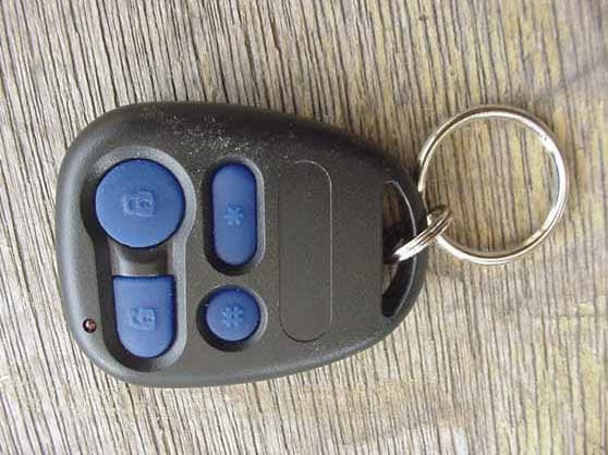
Click to zoom
Application Details
- Equipment Class
- DSC - Part 15 Security/Remote Control Transmitter
- Date of Grant
- May 29, 2003
- Application Purpose
- Original Equipment
- Date of Application
- May 29, 2003
- Equipment Note
- Transmitter
- Frequency Range
- 433.92000000 - 433.92000000
- Company
- Mytek Korea Co
- Country
- South Korea
Documents & Files
Document Text
Text extracted from the exhibit documents filed with the FCC. Open a document above to read the original.
Users Manual
WWW.ULTRASTARTERS.COM OWNER’S GUIDE AUTOMATIC AND MANUAL TRANSMISSION MODELS Advanced Remote Vehicle Starting System 12501250 1250M1250M FCC/ID Notice ATTENTION This device complies with Part 15 of the FCC rules. Operation is subject to the following conditions: (1) This device may not cause harmful interference, and (2) This device must accept any interference received, including interference that may cause undesired operation. CAUTION: Changes or modifications not expressly approved by the part responsible for compliance void the user’s authority to operate this devise. ! -The system must be placed into Service Mode before any service work is started on the vehicle. It is the sole responsibility of the vehicle owner to ensure that this is done. The manufacturer accepts no liability or responsibility for accidental starting of the vehicle. CARBON MONOXIDE - Never Start In A Enclosed Building (Garage, Carport etc..) The Hood Pin Safety Switch Must Always Be Installed! Never Install Automatic Transmission Remote Starters On Manual Transmission Vehicles! See website for a full size printable version of this manual. Owner’s Guide 1. Press and hold the # button for two seconds. 2. The system will flash the park lights and honk the horn(optional) five times. 3. This feature can help find your vehicle in a crowded parking lot. 2 sec. 1.Press and hold the UNLOCK button for three seconds. 2.The doors will unlock, continue holding the unlock button for three more seconds, the trunk release will then activate. The trunk release will be confirmed by one park light flash. Note: The trunk release output will not activate when the ignition key is in the “On” position. 3 sec. 1.Press and release the LOCK button on the remote transmitter. 2.The park lights will flash and the horn (optional) will honk one time. 3.The doors will lock. (With Keyless Entry Option) 4.The LED’s on the antenna will start flashing within five seconds. 1.Press and release the UNLOCK button on the remote transmitter. 2.The park lights will flash and the horn (optional) will honk two times. 3.The doors will unlock. (With Keyless Entry Option) 4.The LED’s on the antenna will stop flashing. 1.Press and hold the LOCK button for three seconds. 2.The park lights will flash and horn will honk (optional) PANIC MODE DISABLE - Press the LOCK button to disable the panic mode and to lock the doors. - Press the UNLOCK button to disable the panic mode and unlock the doors. - Panic Mode will stay activated until disabled by the remote transmitter. 3 sec. 1.Press and release the LOCK & UNLOCK buttons at the same time. 2.If the doors are locked this will unlock the doors without horn honks, the park lights will flash two times to confirm the doors have unlocked. 3.If the doors are unlocked this will lock the doors without horn honks, the park lights will flash one time to confirm the doors have locked. Together Lock Doors Unlock Doors Silent Lock And Unlock Trunk Release Car Finder Mode Panic Mode BASIC OPERATIONSBASIC OPERATIONS REMOTE STARTER FEATURES Press Once to Lock the doors. (Hold For Panic Mode) Press 2nd Time & Hold for Constant Lock Output Press Once to Unlock the doors. Press & Hold for Trunk / Aux Output Press Once for Start -(2 Times if programmed for Safety Start) Press & Hold for 3 seconds to turn off the remote starter. Press & Release then press START and hold for Timer Mode 2nd Car Operation 2nd Car Press the # button at the same time as the command for the second car. This feature requires special programming from the dealer. Turbo Timer Mode 1.While the vehicle is running with the key, press and release the # button. 2.The park lights will turn on and the horn (Optional) will honk once. 3.Turn the ignition key “Off” and the vehicle will continue to run about 2 minutes. While running Owners Guide 3 sec. While running BASIC OPERATIONS REMOTE STARTER FEATURESREMOTE STARTER FEATURES 3 1st 2nd-6 sec Diagnostics Reservation Mode - Manual Transmission Models Only Remote Stop Idle Mode Remote Start Extended Run Time 1.Press and release the button. 2.The Park lights will flash and the horn(optional) will honk one time. 3.When the vehicle has started, the system will flash the park lights four times then remain “On” while the vehicle is running. 4. The vehicle will continue to run for the programmed runtime. (normally 15 minutes). 1.Press and hold the button for three seconds. The remote starter will shut down. 2.The park lights will flash two times and the horn(optional) will honk two times. Note: Pressing the brake pedal or opening hood will also stop the vehicle. 1.While the vehicle is running with key, press the button. 2.The park lights will turn on and the horn(optional) will honk once. 3.Turn the ignition key “Off” and the vehicle will continue to run. 4. Exit the vehicle and leave it running safely without the keys in the ignition. Always lock the doors if the vehicle is left running. Timer Mode. (Starts the vehicle in at a pre-set start interval) 1.Press and release the # button, then press and hold the button for six seconds. The parking lights turn “On” to confirm entering Timer Mode. 2.While the park lights are “On” the start cycle can be selected. 1 hour cycle Press LOCK button 1 Park Light Flash 2 hour cycle Press UNLOCK button 2 Park Light Flashes 3 hour cycle Press button 3 Park Light Flashes 4 hour cycle Press button 4 Park Light Flashes 3.The system will start the vehicle at the selected start cycle. The vehicle will run for it’s runtime then shut off. The system will repeat this for a maximum 24 hour period. TO CANCEL TIMER MODE 1.Press and release the # button, then press and hold the button for four seconds. 2.The System will respond with two flashes and two horn honks (optional). 3. Starting the vehicle with the key or by remote will also disable Timer Mode. # TO INSURE SAFE STARTING OF MANUAL TRANSMISSION VEHICLES 1. With the vehicle running, apply the park brake then press and release the brake pedal. 2. The par…
Text truncated - open the document above for the full version.
Test Report
Report Number: B20212D1 FCC Part 15 Subpart B and FCC Section 15.231 Test Report Transmitter Model: TXM-PT911 114 OLINDA DRIVE, BREA, CALIFORNIA 92823 PHONE: (714) 579-0500 FAX: (714) 579-1850 Page 1 of 16 FCC PART 15, SUBPART B and C TEST REPORT for TRANSMITTER MODEL: TXM-PT911 Prepared for MYTEK KOREA COMPANY 4FL. SHINKUMCHON, TELEPHONE OFFICE #1093, DOKSHAN 1 DONG, KUMCHON-GU, SEOUL, KOREA Prepared by:_____________________ KYLE FUJIMOTO Approved by:____________________ MICHAEL CHRISTENSEN COMPATIBLE ELECTRONICS INC. 114 OLINDA DRIVE BREA, CALIFORNIA 92823 (714) 579-0500 DATE: APRIL 24, 2003 REPORT APPENDICES TOTAL BODY A B C D E PAGES 16 2 2 2 10 15 47 This report shall not be reproduced except in full, without the written approval of Compatible Electronics. Report Number: B20212D1 FCC Part 15 Subpart B and FCC Section 15.231 Test Report Transmitter Model: TXM-PT911 114 OLINDA DRIVE, BREA, CALIFORNIA 92823 PHONE: (714) 579-0500 FAX: (714) 579-1850 Page 2 of 16 TABLE OF CONTENTS Section / Title PAGE GENERAL REPORT SUMMARY 4 SUMMARY OF TEST RESULTS 4 1. PURPOSE 5 2. ADMINISTRATIVE DATA 6 2.1 Location of Testing 6 2.2 Traceability Statement 6 2.3 Cognizant Personnel 6 2.4 Date Test Sample was Received 6 2.5 Disposition of the Test Sample 6 2.6 Abbreviations and Acronyms 6 3. APPLICABLE DOCUMENTS 7 4. Description of Test Configuration 8 4.1 Description of Test Configuration - EMI 8 4.1.1 Cable Construction and Termination 9 5. LISTS OF EUT, ACCESSORIES AND TEST EQUIPMENT 10 5.1 EUT and Accessory List 10 5.2 EMI Test Equipment (Lab X) 11 6. TEST SITE DESCRIPTION 12 6.1 Test Facility Description 12 6.2 EUT Mounting, Bonding and Grounding 12 7. Test Procedures 13 7.1 Radiated Emissions (Spurious and Harmonics) Test 13 7.2 Bandwidth of the Fundamental 15 8. CONCLUSIONS 16 Report Number: B20212D1 FCC Part 15 Subpart B and FCC Section 15.231 Test Report Transmitter Model: TXM-PT911 114 OLINDA DRIVE, BREA, CALIFORNIA 92823 PHONE: (714) 579-0500 FAX: (714) 579-1850 Page 3 of 16 LIST OF APPENDICES APPENDIX TITLE A Laboratory Recognitions B Modifications to the EUT C Additional Models Covered Under This Report D Diagrams, Charts, and Photos • Test Setup Diagrams • Radiated Emissions Photos • Antenna and Effective Gain Factors E Data Sheets LIST OF FIGURES FIGURE TITLE 1 Plot Map And Layout of Radiated Site Report Number: B20212D1 FCC Part 15 Subpart B and FCC Section 15.231 Test Report Transmitter Model: TXM-PT911 114 OLINDA DRIVE, BREA, CALIFORNIA 92823 PHONE: (714) 579-0500 FAX: (714) 579-1850 Page 4 of 16 GENERAL REPORT SUMMARY This electromagnetic emission test report is generated by Compatible Electronics Inc., which is an independent testing and consulting firm. The test report is based on testing performed by Compatible Electronics personnel according to the measurement procedures described in the test specifications given below and in the "Test Procedures" section of this report. The measurement data and conclusions appearing herein relate only to the sample tested and this report may not be reproduced without the written permission of Compatible Electronics, unless done so in full. This report must not be used to claim product endorsement by NVLAP or any other agency of the U.S. Government. Device Tested: Transmitter Model: TXM-PT911 S/N: N/A Product Description: See Expository Statement. Modifications: The EUT was not modified during the testing. Manufacturer: Mytek Korea Company 4FL. Shinkumchon, Telephone Office #1093, Dokshan 1 Dong, Kumchon-Gu, Seoul, Korea Test Date: February 12, 2002 Test Specifications : EMI requirements CFR Title 47, Part 15 Subpart B; and Subpart C, Sections 15.205, 15.209, and 15.231 Test Procedure: ANSI C63.4: 1992 Test Deviations: The test procedure was not deviated from during the testing. SUMMARY OF TEST RESULTS TEST DESCRIPTION RESULTS 1 Conducted RF Emissions, 450 kHz - 30 MHz This test was not performed because the EUT operates on battery power only and cannot be plugged into the AC public mains. 2 Radiated RF Emiss ions, 10 kHz - 4400 MHz Complies with the Class B limits of CFR Title 47, Part 15, Subpart B; and Subpart C, sections 15.205, 15.209, and 15.231. Report Number: B20212D1 FCC Part 15 Subpart B and FCC Section 15.231 Test Report Transmitter Model: TXM-PT911 114 OLINDA DRIVE, BREA, CALIFORNIA 92823 PHONE: (714) 579-0500 FAX: (714) 579-1850 Page 5 of 16 1. PURPOSE This document is a qualification test report based on the Electromagnetic Interference (EMI) tests performed on the Transmitter Model: TXM-PT911. The EMI measurements were performed according to the measurement procedure described in ANSI C63.4: 1992. The tests were performed in order to determine whether the electromagnetic emissions from the equipment under test, referred to as EUT hereafter, are within the Class B specification limits defined by CFR Title 47, Part 15, Subpart B; and Subpart C, sections 15.205, 15.209, and 15.231. Report Number: B20212D1 FCC Part 15 Subpart B and FCC Section 15.231 Test Report Transmitter Model: TXM-PT911 114 OLINDA DRIVE, BREA, CALIFORNIA 92823 PHONE: (714) 579-0500 FAX: (714) 579-1850 Page 6 of 16 2. ADMINISTRATIVE DATA 2.1 Location of Testing The EMI tests described herein were performed at the test facility of Compatible Electronics, 114 Olinda Drive, Brea, California 92823. 2.2 Traceability Statement The calibration certificates of all test equipment used during the test are on file at the location of the test. The calibration is traceable to the National Institute of Standards and Technology (NIST) . 2.3 Cognizant Personnel Mytek Korea Company Timothy Choi Director Compatible Electronics, Inc. Kyle Fujimoto Test Engineer Michael Christensen Test Engineer 2.4 Date Test Sample was Received The test sample was received on February 12, 2002. 2.5 Disposition of the Test Sample The sample has not been returned to Mytek Korea Company as of February 12, 2002. 2.6 Abbreviations and Acronyms The following abbreviations and acronyms may be used in this docu…
Text truncated - open the document above for the full version.
Contact Information
Applicant
Timothy Choi(Company Director)
Technical Contact
Compatible ElectronicsKyle Fujimoto
[email protected]714-579-0500
114 Olinda Drive · Brea, California · United States
Test Firm
Compatible ElectronicsScott McCutchan
714-579-0500Fax: 714-579-1850
Technical Specifications
| # | Rule Parts | Frequency Range | Power Output |
|---|---|---|---|
| 1 | 15.231 | 433.92 MHz - 433.92 MHz | - |
Other Applications from Mytek Korea Co
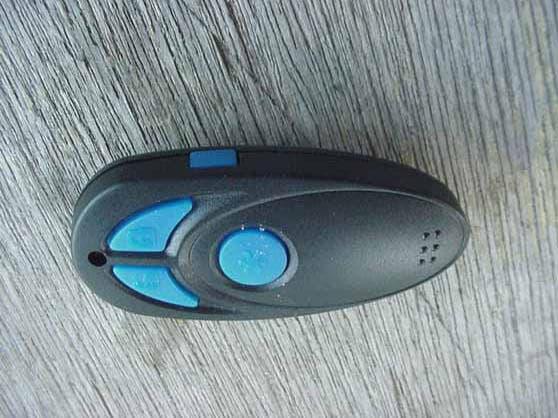
MKYTXPT4G
May 29, 2003Transmitter
Equipment Class
DSC - Part 15 Security/Remote Control Transmitter
MKYTR1350TX
Jul 29, 20022-Way FM Transceiver
Equipment Class
DSR - Part 15 Remote Control/Security Device TransceiverMKYMT9207RX
Aug 20, 1996CRR - Superregenerative Receiver
Equipment Class
CRR - Superregenerative ReceiverMKYSSLRA2RX
Aug 19, 1996Automotive Security System Receiver
Equipment Class
CRR - Superregenerative ReceiverMKYSS850TX
Aug 04, 1996Car Alarm System Transmitter
Equipment Class
DSC - Part 15 Security/Remote Control Transmitter