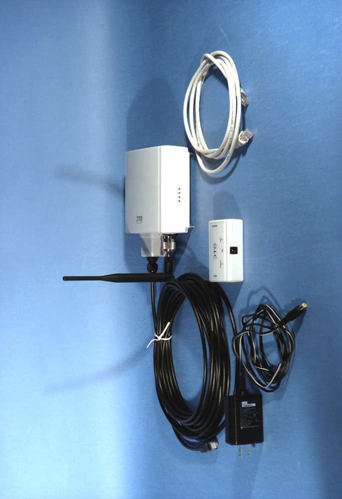
MKZ2411EZYLINK-E2.4GHz Spread Spectrum Station Radio
OTC Wireless Inc
Click to zoom
Application Details
- Equipment Class
- DSS - Part 15 Spread Spectrum Transmitter
- Date of Grant
- Feb 14, 2002
- Application Purpose
- Original Equipment
- Date of Application
- Feb 14, 2002
- Equipment Note
- 2.4GHz Spread Spectrum Station Radio
- Frequency Range
- 2412.00000000 - 2462.00000000
- Company
- OTC Wireless Inc
- Country
- United States
Documents & Files
Document Text
Text extracted from the exhibit documents filed with the FCC. Open a document above to read the original.
Users Manual
2411EZYLINK-E User’s Manual OTC Wireless, Inc. 2 Copyright © 1997-2000 OTC Wireless Inc., Fremont, CA. All rights reserved. This manual is copyrighted with all rights reserved. No part of this publication may be reproduced, transmitted, transcribed, stored in a retrieval system or translated into any language in any form by any means without the written permission of OTC Wireless, Incorporated. Trademarks AirEZY, the AirEZY logo, AMU, OTC Wireless Inc., and the OTC Wireless logo are trademarks of OTC Wireless, Inc. Limited Warranty, Disclaimer, Limitation of Liability For a period of one (1) year from the date of purchase by the retail customer, OTC Wireless Inc., warrants the 2411EZYLINK-E wireless Internet access solution against defects in materials and workmanship. OTC Wireless will not honor this warranty if there has been any attempt to tamper with or remove the unit’s chassis. This warranty does not cover and OTC Wireless will not be liable for any damage or failure caused by misuse, abuse, acts of God, accidents, or other causes beyond OTC Wireless’s control, or claim by other than the original purchaser. If, after inspection, OTC Wireless determines there is a defect, OTC Wireless will repair or replace the 2411EZYLINK-E unit at no cost to you. To return defective merchandise to OTC Wireless please call OTC Wireless Customer Service at (510)-490-8288 to obtain a Return Merchandise Authorization (RMA) Number. In no event shall OTC Wireless, Incorporated be responsible or liable for any damages arising: • From the use of the product • From the loss of use, revenue or profit of the product; or • As a result of any event, circumstance, action, or abuse beyond the control of OTC Wireless, Incorporated; whether such damages be direct, indirect, consequential, special or otherwise and whether such damages are incurred by the person to whom this warranty extends or a third party. Warranty Return Policy If you have a problem with your 2411EZYLINK-E product, please call OTC Wireless Technical Support at (510)490-8288. OTC Wireless Technical Support will assist with resolving any technical difficulties you may have with your OTC Wireless product. After calling OTC Wireless Technical Support, if your product is found to be defective, you may return the product to OTC Wireless after obtaining an RMA number from OTC Wireless Customer Service. The product must be returned in its original packaging. The RMA number should be clearly marked on the outside of the box. OTC Wireless cannot be held responsible for any product returned without an RMA number, and no product will be accepted without an RMA number. When calling OTC Wireless, please provide the following information to expedite service: • Customer account number • Invoice number 3 • Date of Sale • Model number of product • Serial number of product FCC Identification MKZ2411EZYLINK-E FCC Warning This equipment has been tested and found to comply with the limits for a Class B digital device, pursuant to Part 15 of the FCC Rules. These limits are designed to provide reasonable protection against harmful interference in an industrial / commercial installation. This equipment generates, uses, and can radiate radio frequency energy and, if not installed and used in accordance with the instructions, may cause harmful interference to radio communications. However, this is not a guarantee that interference will not occur in a particular installation. IMPORTANT NOTE To comply with FCC RF exposure compliance requirements, the following installation and device operating configuration must be satisfied • Do not alter the antenna. Only use the antenna that is installed in this transmitter. • This device must be installed and placed at the position which can provide at least 2M separation distance from all persons. 4 Table of Content Chapter Title Page 1 Introduction 5 1.1 Theory of Operation 5 1.2 Network Topologies 7 2 Hardware Installation 14 2.1 The Hardware 14 2.2 Installation 16 3 Configuring the AMU 20 3.1 Default Configuration of AMU 21 3.2 Modifying the Default AMU Configuration 21 3.3 Configuring AMU using Web Browser 21 3.4 Configuring AMU using an External SNMP Manager 22 3.5 Telnet 22 3.6 File Transfer to AMU 23 4 Configuring, Monitoring the Base Station 24 and the Client Station 4.1 Using a Browser 24 4.2 Using an External SNMP Manager 34 4.3 AMU Web User Administration 37 5 Product Specifications 40 5.1 Base Station Specifications 40 5.2 Client Station Specifications 41 5 1. Introduction 2411EZYLINK-E is a point-to-multiple-points wireless data networking system. It can be used by internet service providers as a means of last-mile connection to the users. It can also be used to form a campus network. Its data-transmitting burst rate is 11 Mbps. 1.1 Theory of Operation The 2411EZYLINK-E consists of the Base Station 2411EZYLINK-E-BST and the Client Station 2411EZYLINK-E-CPE. The Base Station consists of the Access Management Unit (AMU) 2411EZYLINK- E-BST-AMU and the Base Radio Transceiver 2411EZYLINK-E-BST-TRX. The base station is installed at the site that has access to the Internet backbone or at the central site of a campus network. The Client Station consists of the Client Radio Transceiver 2411EZYLINK-E-CPE-TRX and/or the Buffer Box 2411EZYLINK-E-CPE-BFB. The client station is installed at the Internet service subscribers’ site or the satellite site in a campus network. All the 2411EZYLINK-E equipment is designed to work with Ethernet interface. The Radio Transceiver converts the Ethernet data packets into radio packets and uses direct sequence spread spectrum modulation to turn the data packets into 2.4 GHz radio signals. The Base Radio Transceiver and the Client Radio Transceivers each has a unique RFID. A packet to be relayed between two stations uses the RFID of the originating transceiver as its source address and the RFID of the intended receiving transceiver as its destination address. The packet transmitted by the originating t…
Text truncated - open the document above for the full version.
Block Diagram
block11Mbps York Sung/Thomas Lo Sept. 2001, rev. 2 DM9008 U6 Network Interface Control P51XAG3 U4 CPU HFA3861 U10 DSS Base-band Processor AS7C31026 U3 SRAM Modulator Up-converter DMP-VCX748 U15 748 MHz VCO IF LO RF PLL UPG152TA U20 T/R Switch Down Converter Demodulator MDR743F FL3 RF Filter Ethernet Interface 855653L1 FL1 IF Filter SkyFish11Mbps Radio Functional Block Diagram IF PLL DMP-VCX2074 U23 2.407GHz VCO RF LO T/R Switch IF Amp LNA HFA3783 IQ Modulator /Demodulator & Synthiesizer U14 HFA3683 RF-IF Converter & Synthesizer U21 Driver Amp Power Amp HFA3983 U24 XCS10XL-4C U9 FPGA F4106 U17 44MHz Oscillator AT29LV010A U5 Flash OSC-3NCLN Y10 44MHz Oscillator j MDR743F FL4 RF Filter
Cover Letter(s)
From: Denise Teng Sent: Thursday, February 14, 2002 1:36 PM To: Mike Kuo Subject: FW: OTC WIRELESS, INC., FCC ID:MKZ2411EZYLINK-E, AN01T1669, CCS project no:01U1006 Hi Mike, Here's the new MPE calculation. regards, -----Original Message----- From: Denise Teng Sent: Thursday, February 14, 2002 12:30 PM To: Mike Kuo Cc: Steve Cheng; Hue Vang; Anne Liang Subject: RE: OTC WIRELESS, INC., FCC ID:MKZ2411EZYLINK-E, AN01T1669, CCS project no:01U1006 Hi Mike, Please see attached files for the revised test report and revised User Manual. If you need me to upload to TCB again, please let me know. Thanks! regards, Denise -----Original Message----- From: Steve Cheng Sent: Wednesday, February 13, 2002 9:25 PM To: Mike Kuo; Hue Vang Cc: Denise Teng; Anne Liang; Steve Cheng Subject: RE: OTC WIRELESS, INC., FCC ID:MKZ2411EZYLINK-E, AN01T1669, CCS project no:01U1006 Dear Mike, We have put the answers immediate follow each of your question below. Thanks. Best regards, Steve -----Original Message----- From: Mike Kuo Sent: Monday, February 04, 2002 6:25 PM To: Steve Cheng; Hue Vang Cc: Denise Teng; Anne Liang Subject: OTC WIRELESS, INC., FCC ID:MKZ2411EZYLINK-E, AN01T1669, CCS project no:01U1006 Importance: High Question #1: In accordance with user manual, the designed output power is 100mW. However, the max. output measured with Spectrum analyzer is 230.14mW/Low Channel, with power meter is 40.74mW/High Channel, with Summation method is 162.76mW/Low channel. Please explain the differences. Please ignore the 40.74mW average power reading and 230.14 spectrum reading. Those are for eng info only. We have remove it from the original report and new report have been up-loaded. Question #2: MPE calculation submitted is using 23.6dBm as max. conducted output power with 18 dBi antenna gain. The calculated separation distance is 34 cm which is over 20cm. Based upon the description is user manual, the requirement separation distance for this device which the antenna is fixed-mounted on outdoor permanent structures is 2 meter. The user manual is indicating 20cm separation distance. However, in order to determine the correct separation distance, the answer for question #1 has to be provided. We have corrected the separation distance to 2M in the users manual. Best Regards ========================= Mike Kuo Compliance Certification Services 561F Monterey Road Morgan Hill CA 95037 Telephone number:408-463-0885 EXT:105 Fax number :408-463-0888 E-Mail:[email protected]
Cover Letter(s)
October 25, 2001 To whom it may concern, The changes we did here are: Mod.#1 Added ferrite core (Fair-Rite, Part # 0444164181) onto RJ45 with single turn. Mod.#2 Added ferrite core (Fair-Rite, Part # 0443164151) onto DC Power Line with two turns. Mod.#3 Replacing the R75 (0ohm), R76 (0ohm) with ferrite bead. Yan Zheng Production Engineer
ID Label/Location Info
PROPOSED FCC ID LABEL AND LOCATION OTC WIRELESS, INC. This device complies with Part 15 of the FCC Rules. Operation is subject to the following two conditions: (1) this device may not cause harmful interference, and (2) this device must accept any interference received, including interference that may cause undesired operation. FCC ID: MKZ2411EZYLINK-E FCC ID LABEL FCC ID LABEL
Operational Description
5 1. Introduction 2411EZYLINK-E is a point-to-multiple-points wireless data networking system. It can be used by internet service providers as a means of last-mile connection to the users. It can also be used to form a campus network. Its data-transmitting burst rate is 11 Mbps. 1.1 Theory of Operation The 2411EZYLINK-E consists of the Base Station 2411EZYLINK-E-BST and the Client Station 2411EZYLINK-E-CPE. The Base Station consists of the Access Management Unit (AMU) 2411EZYLINK- E-BST-AMU and the Base Radio Transceiver 2411EZYLINK-E-BST-TRX. The base station is installed at the site that has access to the Internet backbone or at the central site of a campus network. The Client Station consists of the Client Radio Transceiver 2411EZYLINK-E-CPE-TRX and/or the Buffer Box 2411EZYLINK-E-CPE-BFB. The client station is installed at the Internet service subscribers’ site or the satellite site in a campus network. All the 2411EZYLINK-E equipment is designed to work with Ethernet interface. The Radio Transceiver converts the Ethernet data packets into radio packets and uses direct sequence spread spectrum modulation to turn the data packets into 2.4 GHz radio signals. The Base Radio Transceiver and the Client Radio Transceivers each has a unique RFID. A packet to be relayed between two stations uses the RFID of the originating transceiver as its source address and the RFID of the intended receiving transceiver as its destination address. The packet transmitted by the originating transceiver can be received by all the transceivers within the effective receiving range. Only the transceiver with the correct RFID matching the destination address will process the information contained in the packet. All the other stations will discard the packet. Each packet is encrypted before being transmitted by the radio. The RF channel and the encryption code have to be set the same for two stations to communicate with each other. The Base Station and all the Client Stations are pre-configured in the factory with the same default RF channel and encryption code. The user system administrator can use OTC’s system administration software to change the settings (see Chapter 4 for details). The communication between the Client Stations and the Base Station is based on a polling process. The RFID of each Client Station to be served by a Base Station needs to be registered in a polling list stored in the Base Station transceiver. The OTC’s system administration software can be used to add or delete the RFIDs of the Client Station transceivers in the Base Station transceiver. In addition to the Client Station access management, The Access Management Unit (AMU) provides the following functions: 1. Flow control between the network backbone and multiple Base Radio Transceivers. 2. SNMP and Web based Interface for monitoring and configuring the multiple Base RadioTransceivers (one AMU can be connected to up to 4 Base Radio Transceivers via a switching hub) and the Client RadioTransceivers servered by each Base Transceiver Radio. 3. Ethernet bridging, including Spanning Tree support. The use of the Buffer Box at the Client Station is optional. If the client site has only a small number of computer stations, the use of the Buffer Box may not be required. When the number of computer stations on the client site is greater than eight, it is recommended that a Buffer Box be used with the Client Radio Transceiver. The Buffer Box provides the following functions: 1. Flow control between the client’s local network and the Client Transceiver Radio. 6 2. Ethernet bridging, including Spanning Tree support. Please refer to Chapters 3 and 4 for using and configuring the AMU and the 2411EZYLINK-E network system. 1.1 Typical System Configuration using 2411EZYLINK-E (Single Radio Base Station) . Multiple-radio Base Station Hub /Switch / Router 2411EZYLINK-E -CPE-TRX Client Station without Buffer Box 2411EZYLINK-E -CPE Small Network ( < 8 computer stations) 2411EZYLINK-E -CPE-BFB 2411EZYLINK-E -CPE-TRX Hub /Switch / Router Client Station with Buffer Box 2411EZYLINK-E -CPE Large Network (>8 computer stations) Base Station 2411EZYLINK-E 2411EZYLINK-E & 2411EZYLINK-9 -BST-AMU 2411EZYLINK-E -BST-TRX Internet Backbone Access Management Unit Base Radio Transceiver Client Radio Transceiver Buffer Box Client Radio Transceiver 2411EZYLINK-E BST- 2411EZYLINK-E BST- Interne Backbon 2411EZYLINK-E ISP- BST- 2411EZYLINK-E ISP- BST- 2411EZYLINK-E ISP- BST- Switc Access Management Base Radio Base Radio
Operational Description
Necessary Explanations to present to TELEC for certification. 1. Outline of Design and Development We need more explanations in details in writing with describing exact names of parts and numerical values. 1) How "Stability of Frequency" is designed ? We design and control the frequency stability by Phase-locked-loop control implemented in the Synthesizers contained in the HFA3683 RF-IF converter IC, U21, and the HFA3783 IQ Modulator and demodulator IC, U14. VCO’s (DMP-VCX2074, U23 for RF, DMP-VCX743, U15 for IF) feed the LO to the synthesize and their frequencies are compared to reference clock with temperature- guaranteed stability of +/-25ppm with a stabilized power supply. 2) How "Spurious Emissions" is suppressed ? Components of Spurious are few due to the fact that we design to get the Transmission Frequency directly from the output of VCO, and in addition we suppress the emission from antenna by inserting BPF (SAW filter, FL1 for the IF) and two BPF in the RF transmission chain--FL4 before the PA and FL3 between the PA and the antenna.. 3) How "Frequency Modulation" is controlled and limited ? We utilized the balanced differential analog signals from the accurate transmit DAC inside the DSS Base Band Processor HFA3861, U10 .as the input to the IQ modulator inside HFA3783, U14. In addition, this signal is dc-coupled and digitally filtered. The combined accuracy in the IQ input and the base-band filtering keeps the spread bandwidth constant. 4) How "Transmit Power" is controlled and limited ? We design to stabilize the Transmission Power by reading the power level from the voltage of a detector integrated with the Power Amp IC, HFA3983, U24 and then adjust the drive amp gain to maintain a constant transmission power. 5) How "secondarily emitted radio wave from Receiver" is suppressed ? We implemented automatic gain control (AGC) for the receiving circuit. The AGC works to keep the amplitude of the received signal constant along the receiving chain to minimize spurious signal growth due to the non-linearity of the components of the receiving circuit. 2. Considerations to environment of use. We need more explanations in details with describing exact names of parts and numerical values. 1) Temperature Test : ETSI 300 328 tested at –0°C to +55C 2) Humidity Test ETSI 300 019 tested for 5 days at >92% RH at 50°C 3. Designed Specifications and Acceptable Technical Reference Specifications ( 1 ) Transmitter * Frequency Tolerance Designed value : < ±25 ppm Technical reference ETS 300 328 * Occupied Frequency Bandwidth Tolerance Designed value : Fcenter ± 13MHz at –25dBc points Technical reference : FCC part 15.247 * Spreading bandwidth Designed value : 11 MHz at –10dB Technical reference : FCC part 15.247 * Spreading Factor. Value : 11 Mchips/sec at 1.375 Msymbols/sec at 11 mbps datarate. * Spurious Emission Strength Designed value : in compliance with ETS 300328 and FCC part 15.247 Technical reference: ETS 300328 and FCC part 15.247 * Antenna Power and its tolerance Design value : +13.6dBm +1dB, -2dB Technical reference : ETS 300 328 and FCC part 15.247 * Emitted power to adjacent channel Design value : < -30 dBc Technical reference : FCC part 15.247 ( 2 ) Receiver * Secondarily emitted radio wave strength Designed value : in compliance with ETS 300328 and FCC part 15.247 Technical reference: ETS 300328 and FCC part 15.247 4. Explanations of Operations at every part (section) based on Block Diagram. See attached data sheets in pdf format for an example.
Parts List/Tune Up Info
ANT-PATCH-12 2.4 GHz 12 dB Gain Patch Antennas For wireless LAN and ISM band applications s. Advantages Superior performance due to excellent Cross Pole patterns. Flat design provides high efficiency and low back lobes with minimal depth dimension. Easy to install Ball Mount Bracket. Light weight design saves on shipping costs. Broad beam width option allows wide area coverage. Electrical Mechanical Gain, min 12 dB Weight (+ mount) 2 lb Horizontal beamwidth 38 ° Width – in (cm) 8.5 (21.6) Vertical beamwidth 38 ° Height – in (cm) 8.5 (21.6) Front/Back Ratio >30dB Depth – in (cm) 1.125 (2.8) Polarity Linear Lateral thrust@100MPH 10 (22) VSWR 1.5:1 Torsional moment @100MPH with Standard Mount-ft/lbs (m/kg) 0.2 (0.22) Cross polarization >30dB Wind loading –in2 (cm2) 72 (466) Input Power 100 Watts Connector N Female 2.4GHz E-Plane & H-Plane plot of the 12 dB ISM Panel Antenna a Teletronics International Inc. 1803 Research Blvd. Suite 404 Rockville MD 20850 Phone: 301-309-8500 * Fax: 301-309-8851 [email protected] * www.teletronics.com. TELETRONICS INTERNATIONAL ANT-PATCH-18 2.4 GHz 18 dB Gain Patch Antennas For wireless LAN and ISM band applications s. Advantages Superior performance due to excellent Cross Pole patterns. Flat design provides high efficiency and low back lobes with minimal depth dimension. Easy to install Ball Mount Bracket. Light weight design saves on shipping cost. Broad beam width option allows wide area coverage. Electrical Mechanical Gain: min 18dB Weight (+ mount) : 4 lb Horizontal beamwidth: 18 ° Width – in (cm) : 15.5 (39.4) Vertical beamwidth: 18 ° Height – in (cm) : 15.5 (39.4) Front/Back Ratio: >30dB Depth – in (cm) : 1.125 (2.8) Polarity: Linear Lateral thrust@100MPH: 15 (33) VSWR: 1.5:1 Torsional moment @100MPH with Standard Mount-ft/lbs: (m/kg) 0.4 (0.88) Cross polarization: >30dB Wind loading –in2 (cm2): 240 (1552) Input Power : 100 Watts Connector : N Female 2.4GHz E-Plane & H-Plane plot of the 18 dB ISM Panel Antenna a Teletronics International Inc. 1803 Research Blvd. Suite 404 Rockville MD 20850 Phone: 301-309-8500 * Fax: 301-309-8851 Email: [email protected] * www.teletronics.com TELETRONICS INTERNATIONAL
RF Exposure Info
MPE CALCULATION for OTC MKZ2411EZYLINK-E Formula used in the MPE Calculations: E^2/3770 = S, mW/cm2 Pwatts*Ggain = 10^(PdBm-30+GdBi)/10) E, V/m = (Pwatts*Ggain*30)^.5/d, meters d = ((Pwatts*G*30)/3770*S))^0.5 --------- (A) Since S (mW/cm2) =1.00from 1.1310 Table 1 P (dBm) =22.1EUT output power G (dBi) =18.0EUT antenna gain Substitute these parameters into the A above, we have MPE safe distance d (cm) = 28.5 NOTE: For fixed location transmitters with outdoor antenna, minimum separation distance is 2 meter, even if calculations indicate MPE distance is less
Schematics
A A TITLE: ENGINEER: DRAWN BY:SHEET: DATE: REV: OF E D C B A 7654321 7654321 APPR.DATEDESCRIPTIONLTRZONE E D 8 REVISIONS FF 8 8-02-01 SLIDE 2.84V 55 NOTE: CALCULATED FOR ICP = 250UA RF section schematics 8 1700-24EZ-01-01 York Sung York Sung A B C critical 50 ohm trace, w = 14 mils critical 50 ohm trace, w = 14 mils 44MHZ_CW IF+ IF- LE_PLL PE2 RX_RF_GN CLK_PLL DIN_PLL TX_DET GLOBAL$AGND GLOBAL$AGND GLOBAL$VCCB GLOBAL$AGND GLOBAL$AGND GLOBAL$AGNDGLOBAL$AGNDGLOBAL$AGND GLOBAL$AGND GLOBAL$AGND GLOBAL$AGND GLOBAL$AGND GLOBAL$AGND GLOBAL$AGND GLOBAL$AGND GLOBAL$AGND GLOBAL$AGND AGND PE1 GLOBAL$VCCC GLOBAL$VCCA AGND GLOBAL$AGND GLOBAL$AGND GLOBAL$AGND GLOBAL$AGND GLOBAL$+3.3V GLOBAL$+3.3V AGND GLOBAL$+3.3V GLOBAL$AGND AGNDAGND GLOBAL$AGND GLOBAL$AGND GLOBAL$AGND AGND GLOBAL$AGND GLOBAL$AGND GLOBAL$AGND AGND GLOBAL$AGND GLOBAL$AGND GLOBAL$AGND GLOBAL$AGND AGND GLOBAL$AGND AGND GLOBAL$AGND GLOBAL$AGND 3.3V_ANA VCCA VCCB VCCC 3.3V_ANA 3.3V_ANA CLK_PLL DIN_PLL TR_EN PE2 TR_EN 649 R100 0PF (No Lo ad) C116 1.5K R97 100PF C1 32 220PF C120 0.1UF C1 05 10K R100A1 C115 4.7PF OUT IN GROUNDS FL4 MDR743F 1 2 3 4 0.01 UF C1 42 GND BP SHDN OUTIN U19 MAX8867EUK29 1 2 34 5 0.1UF C1 56 R87 0 C1 17 0PF (No Lo ad) 1000PF C146 R84 0 R851k 1 2 C124 0.1UF 10UF C103 1000PF C149 0.01UF C135 7PFC137 10UF C131 C114 7PF RF GROUNDS VCONT VCC U23 DMP VCX2074S6 1 3 5 24678 0.1UF C1 04 R96 3.74K VCC GROUNDS OUT IN U22 UPC2745TB 1 23 4 5 6 1000PF C1 63 C127 0.01UF BLM21P3 00S L17 10K R100C1 R92 82 C134 7PF OUT IN GROUNDS FL3 MDR743F 1 2 3 4 22PF C129 C122 0.01UF 10K R100B1 7PF C119 R98 3.74K C107 0.01 UF L16 2.2NH 20 R82 7PF C147 1000PF C159 3.3 PF C108 C1 43 0.01 UF 1000PF C162 100 R90 1000PF C160 11 .5K R80 10 R93 7PF C1 52 1000PF C121 1000PF C164 0.01UF C1 06 7PF C112 91 R95 LO_GND LO_GND GNDGND GND GND GND GND PE2 PE1 TX_VCC2 TXA_OUT TXA_SUB TX_MX_VCC2- TX_MX_OUT TX_MX_VCC2 TX_MX_VCC1 TX_LO_DR_VCC FLAG1 LO_IN+ LO_IN- FLAG2 LO_VCC RX_LO_DR_VCC TX_MX_IN- RX_MX_OUT- RX_M X_OUT+ TX_MX_I N+ TX_M X_IND RX_ MX_IN PR E_GND PR E_VDD BIAS_GND ITAT_ RES1 BIAS_ VCC CP_ GND CP_D O CP _VDD TXA_ IN TX_VCC1 GND LNA_VCC RX_IN GND BIAS_VCC BIAS_GND H/L LEDATACLKRE F_BY RE F_IN SYN_SUB/GND SYN_V DD SYN_SUB/ GND LD TX_MX_VCC2+ PTAT A_RES GNDGND GND RF_ OUT COL_ OUT ITAT_ RES2 U21 HFA3683A 1 2 3 4 5 6 7 8 9 10 11 12 13 14 15 16 17181920212223242526272829303132 33 34 35 36 37 38 39 40 41 42 43 44 45 46 47 48 49505152535455565758596061626364 1000PF C138 91 R91 1000PF C165 7PF C153 C74D1 10PF 100 R88 C1 45 1000 PF 1.8NH L13 1000PF C158 C1 54 7PF GND GND VCC GND DET_OUT GND GND GND GND GND GND GND GNDGND GND GND GND GND PE VCC * PIN OUT TO CHANGE SUBJECT PADDLE GND GND VCC REXT_OS REXT_DS VCC_DS RFOUT RFIN U24 HFA3983IV 1 2 3 4 5 6 7 8 9 10 11 12 13 1415 16 17 18 19 20 21 22 23 24 25 26 27 28 29 C110 0.01UF R81 9.53K R101510 1 2 1.5K R79 1000PF C139 D2 LU20111_R 1 2 0.1UF C144 7PF C125 1000PF C148 100 R103 270PF C130 C109 4. 7PF C126 7PF L18A 4.7 NH 100 R102 10 R94 100 R104 GND OUT2 OUT1 CONT2 V IN V CONT1 U20UPG152TA-E3 1 2 34 5 6 L10 1.2NH BLM21P300S L19 0.01 UF C118 33NH L12 D3 LU20115_G 1 2 J31 MCX_connector 1 0.06 8UF C140 L18 6.8 NH L15 33NH C1 51 2.7 PF 0.01UF C136 1.8NH L11 10K R74A1 0.01UF C133 0.1UF C1 01 0.01UF C128 C155 1000PF 10K R74B1 0.01UF C123 1.0PF C150 1.1K R83 10K R99 1.1 K R86 1.2NH L14 0.68UFC1 41 10UF C102 C113 4.7PF 220PF C111 100 R89 1 1 2 2 3 3 4 4 5 5 AA BB CC DD TITLE: ENGINEER: DRAWN BY:SHEET: DATE: REV: OF E D C B A 7654321 7654321 APPR.DATEDESCRIPTIONLTRZONE E D C B A 8 REVISIONS FF 8 York Sung 8 York Sung NOTE: CALCULATED FOR 2.84V 45 ICP = 250UA 8-02-01 IF section schematics critical 50 ohm trace, w = 14 mils 1700-24EZ-01-01 1700-24EZ-01-01 IF+ IF- RX_DET RX_AGC TXI+ TXQ+ GLOBAL$+3.3V GLOBAL$DGND GLOBAL$VCCC GLOBAL$VCCC GLOBAL$VCCB VREF GLOBAL$AGND GLOBAL$AGNDGLOBAL$AGND GLOBAL$AGND GLOBAL$AGND GLOBAL$AGND GLOBAL$AGND GLOBAL$AGND GLOBAL$AGND GLOBAL$AGND GLOBAL$AGND GLOBAL$AGND GLOBAL$AGND GLOBAL$AGND GLOBAL$AGND GLOBAL$AGND GLOBAL$AGND GLOBAL$AGND GLOBAL$AGND GLOBAL$AGND GLOBAL$AGND PE1 GLOBAL$AGND 44MHZ_CW GLOBAL$AGND GLOBAL$AGND GLOBAL$AGND GLOBAL$AGND GLOBAL$AGND GLOBAL$AGND GLOBAL$AGND GLOBAL$AGND GLOBAL$AGND TX_AGC VCCBVCCC 3.3V_ANA VCCA VCCC VCCC VCCB 3.3V_ANA GND 3.3V_ANA 3.3V_ANA 3.3V_ANA VCC TXI- TXQ- CLK_PLL LE_PLL2 DIN_PLL LED AGND PE2 VCC PE2 TR_EN RXI+ RXI- RXQ+ RXQ- R77 1k 1 2 10UF C54 C890.022U F C92 GRM230Y5V106Z010AL 1 2 0.1U F C57 C91 0.22UF 2KR73 0R64A 100PF C82 100PF C79 100R101B1 0 R62 R72 3.92K GND BP SHDN OUTIN U13 MAX8867EUK29 1 2 34 5 49. 9 R71 C99 0.1UF C90 3900 PF C97 1000PF 1000PF C157 0.1UF C76 0 R75 10 UF C55 10K R102A1 C96 0.1UF GND ENB VDD OUT U17 F4106-44.000M 1 2 3 4 0.1UF C84 220PF C73 0.1U F C56 10K R102B1 220PF C68 RF GROUNDS VCONT VCC U15 DMP VCX-748S6 1 3 5 24678 U18A TC7S00FCT 1 2 4 5 3 C94 GRM230Y5V106Z010AL 1 2 0 R76 D1 LU20111_R 1 2 0.1UF C77 10K R102C1 L2 39NH R78 1k 1 2 1.5K R74 68PF C78 0.56U H L9 C71 68PF D4 LU20117_Y 12 100 R51 R70 0 CASE GROUNDS CASE GROUNDS IN MAY CHANGE * PINOUT OUT RET OUT RET IN FL1 SAWTEK_855653 12 3 4 56 78 9 10 1112 0 R66 C9822 PF 0 R63 0 R64 100 R52 0 R60 100 PF C58100PFC59 100R101A1 C74 15PF 100R101C1 U16 LX8117-3.3 1 23 GND VOUTVIN C69 15PF C95 GRM230Y5V106Z010AL 1 2 L8 BLM21P300S L3 22NH C83 0.1UF C75 10PF C72 10PF 220PF C66 C100 0.1UF 33NH L4 R652K 220PF C70 0 R65A C60 1000PF C93 GRM230Y5V106Z010AL 1 2 33NH L5 0.1UFC80 RX_AGC_ GND RX_AGC_VCC RXI - RXI+ CA L_EN RX_B B_GND RX_BB_VCC RX_DE M_GND PE2 PE1 RX_ VAGC IF_ DETECT RX_AGC_S UB LO_SUB LO_IN- LO_IN+ LO_VCC LO_GND TXQ- TXQ+ 1.2V_OUT TXI- TXI+ RXQ- RXQ+ SYN TH_SUB SY NTH_GND SYNTH_VDD CLKDATALE CP _VDD CP_D O CP_ GND LD REF_B Y RE F_IN TX_BIAS_GND IF_RX- SPARE IF_RX+ TX_VAGC TX_BIAS_VCC TX_AGC_SUB TX_AGC_GND TX_AGC_VCC IF_TX- IF_TX+ U14 HFA3783 1 2 3 4 5 6 7 8 9 10 11 12 131415161718192021222324 25 26 27 28 29 30 31 32 33 34 35 36 373839404142434445464748 0.1U F C81 10k R48 0.1U F C67 0.1UF C52 2.87 K R57 1000PF C86 C85 1000PF L7 BL M21P300S 0.1UF C88 0.1UF C53 L6 BLM21P300S 0.1UF C61 0…
Text truncated - open the document above for the full version.
Test Report
FCC CFR47 PART 15 CERTIFICATION TEST REPORT FOR 2.4GHz SPREAD SPECTRUM STATION RADIO MODEL: 2411EZLink-E FCC ID: MKZ2411EZYLINK-E REPORT NUMBER: 01U1006-1 ISSUE DATE: OCTOBER 2, 2001 Prepared for OTC WIRELESS INC. 48507 MILMONT DRIVE FREMONT, CA 94538 USA Prepared by COMPLIANCE CERTIFICATION SERVICES 561F MONTEREY ROAD, MORGAN HILL, CA 95037, USA TEL: (408) 463-0885 FAX: (408) 463-0888 REPORT NO: 01U1006-1 FCC ID: MKZ2411EZYLINK-E EUT: 2.4 GHz Spread Spectrum Station Radio DATE : October 18, 2001 Page 2 of 63 COMPLIANCE CERTIFICATION SERVICES DOCUMENT NO: CCSUP4031A 561F MONTEREY ROAD, MORGAN HILL, CA 95037 USA TEL: (408) 463-0885 FAX: (408) 463-0888 This report shall not be reproduced except in full, without the written approval of CCS. This document may be altered or revised by Compliance Certification Services personnel only, and shall be noted in the revision section of the document. TABLE OF CONTENT 1. TEST RESULT CERTIFICATION------------------------------------------------------------------------3 2. EUT DESCRIPTION------------------------------------------------------------------------------------------4 3. TEST METHODOLOGY------------------------------------------------------------------------------------4 4. TEST FACILITY----------------------------------------------------------------------------------------------4 5. ACCREDITATION AND LISTING-----------------------------------------------------------------------4 5.1. Laboratory Accreditations and Listings----------------------------------------------------------------5 6. MEASURING INSTRUMENT CALIBRATION--------------------------------------------------------6 6.1. Measurement Uncertainty--------------------------------------------------------------------------------6 7. SUPPORT EQUIPMENT / TEST DIAGRAM-----------------------------------------------------------7 8. APPLICABLE RULES AND BRIEF TEST RESULT--------------------------------------------------8 9. MODIFICATIONS-------------------------------------------------------------------------------------------13 10. TEST SETUP, PROCEDURE AND RESULT-------------------------------------------------------14 10.1. CONDUCTED POWER-------------------------------------------------------------------------------14 10.2. 6 dB BANDWIDTH MEASUREMENT--------------------------------------------------------------19 10.3. CONDUCTED SPURIOUS EMISSION-------------------------------------------------------------23 10.4. PEAK POWER SPECTRAL DENSITY--------------------------------------------------------------33 10.5. PROCESSING GAIN----------------------------------------------------------------------------------37 10.6. RESTRICTED BAND EDGE MEASUREMENT---------------------------------------------------43 10.7. RADIATED EMISSION-------------------------------------------------------------------------------47 10.8. POWER LINE CONDUCTED EMISSION---------------------------------------------------------54 10.9. SETUP PHOTOS--------------------------------------------------------------------------------------59 REPORT NO: 01U1006-1 FCC ID: MKZ2411EZYLINK-E EUT: 2.4 GHz Spread Spectrum Station Radio DATE : October 18, 2001 Page 3 of 63 COMPLIANCE CERTIFICATION SERVICES DOCUMENT NO: CCSUP4031A 561F MONTEREY ROAD, MORGAN HILL, CA 95037 USA TEL: (408) 463-0885 FAX: (408) 463-0888 This report shall…
Text truncated - open the document above for the full version.
Contact Information
Applicant
Jen Tsao(Program Director)
Test Firm
Compliance Certification Services IncSteve Cheng
Technical Specifications
| # | Rule Parts | Frequency Range | Power Output |
|---|---|---|---|
| 1 | 15C | 2.41 GHz - 2.46 GHz | 163.00 mW |
Other Applications from OTC Wireless Inc
MKZTRIMAR
Sep 08, 2005802.11a/b/g Wireless Ethernet Transceiver
Equipment Class
DTS - Digital Transmission System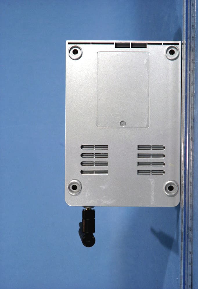
MKZWIJET11G
Apr 29, 2004802.11g Wireless Projector/ Monitor Adapter
Equipment Class
DTS - Digital Transmission System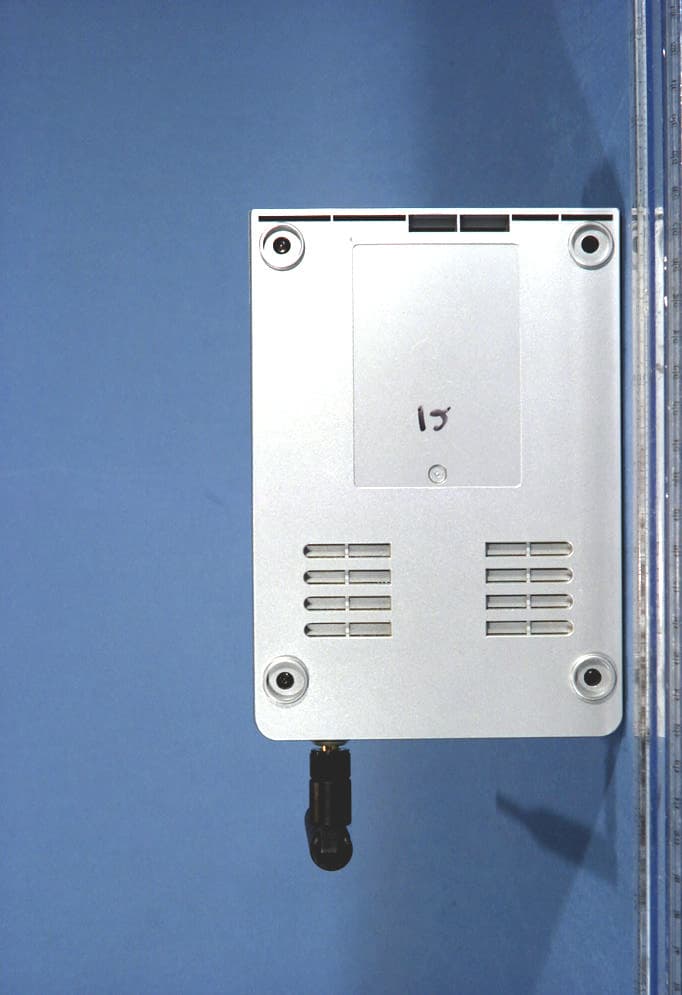
MKZWIJETVIDEO
Apr 29, 2004802.11g Wireless Projector/ Monitor Adapter
Equipment Class
DTS - Digital Transmission System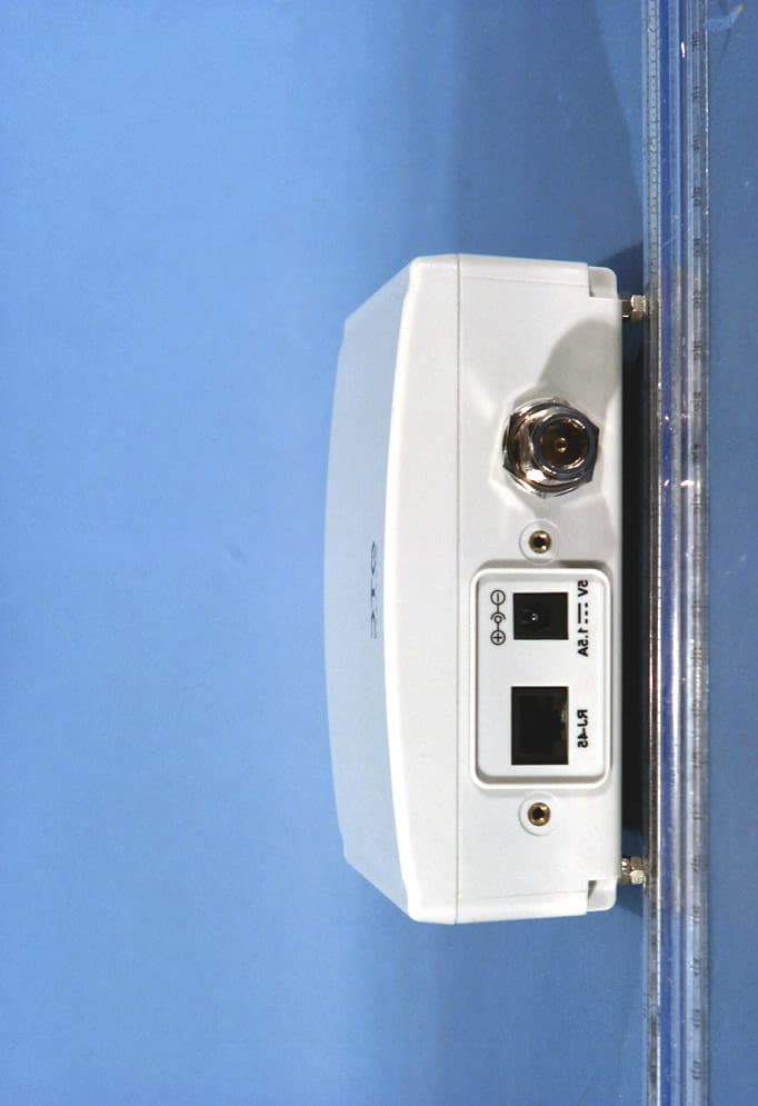
MKZAVCW11G682E
Oct 07, 2003Wireless Ethernet Adapter
Equipment Class
DTS - Digital Transmission System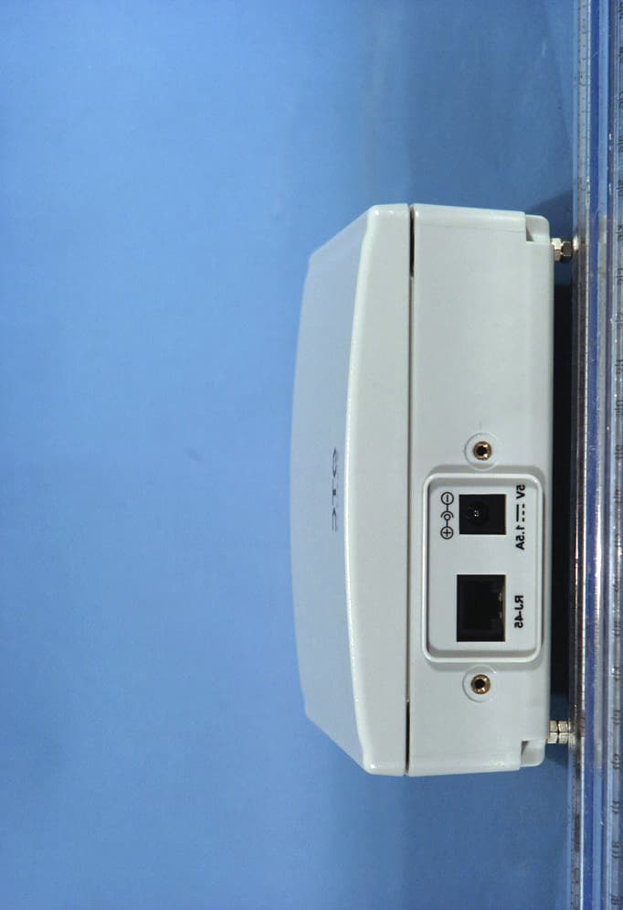
MKZAVCW11G682
Sep 29, 2003Wireless Ethernet Adapter
Equipment Class
DTS - Digital Transmission System