MKZTRIMAR802.11a/b/g Wireless Ethernet Transceiver
OTC Wireless Inc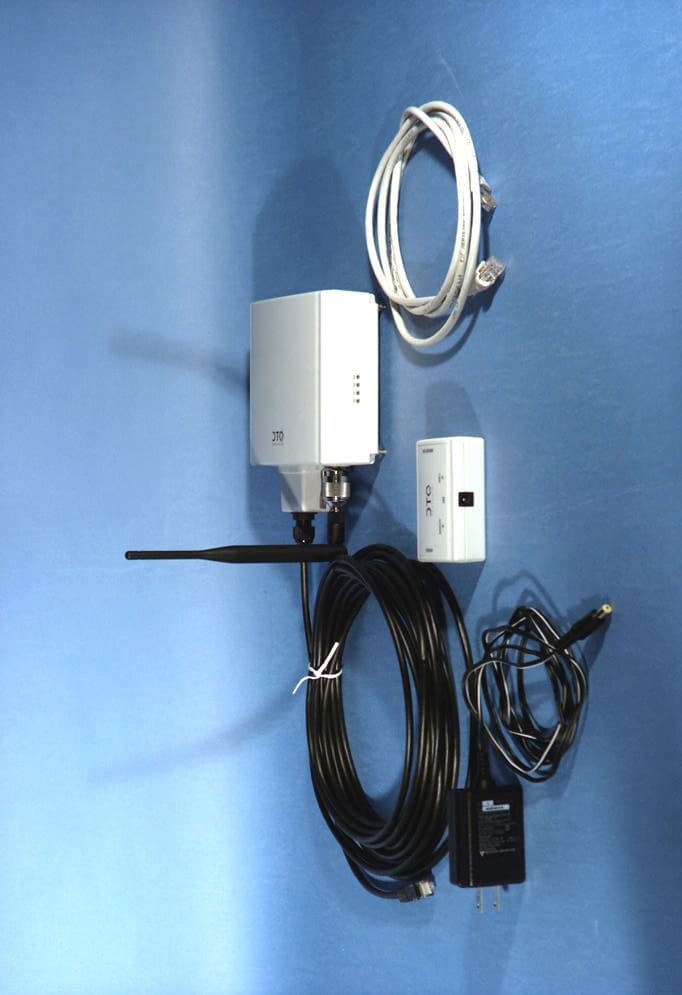
Click to zoom
Application Details
- Equipment Class
- DTS - Digital Transmission System
- Date of Grant
- Sep 08, 2005
- Application Purpose
- Original Equipment
- Date of Application
- Sep 08, 2005
- Equipment Note
- 802.11a/b/g Wireless Ethernet Transceiver
- Frequency Range
- 5745.00000000 - 5825.00000000
- Company
- OTC Wireless Inc
- Country
- United States
Documents & Files
Document Text
Text extracted from the exhibit documents filed with the FCC. Open a document above to read the original.
Users Manual
Trimar - Tri-Mode Advanced Radio - AP 802.11a/g/b Advanced Wireless LAN Access Point Technical Manual www.otcwireless.com ASR-G-102 Technical Manual ii Trimar-AP Trimar Wireless LAN Access Point Technical Manual Copyright Information in this document is subject to change without notice. Complying with all applicable copyright laws is the responsibility of the user. No part of this document may be reproduced or transmitted in any form or by any means, electronic or mechanical, for any purpose, without the express written permission of the seller. If, however, your only means of access is electronic, permission to print one copy is hereby granted. The seller provides this documentation without warranty, term, or condition of any kind. The seller may make improvements or changes in the product(s) and/or the program(s) described in this documentation at any time. Other product and company names herein may be trademarks of their respective owners. Copyright 2005 OTC Wireless, Inc. All rights reserved. Rev 1.00 ASR-G-102 Technical Manual iii Table of Contents Trimar AP Technical Manual Chapter 1: Introduction.............................................................................................................................4 1.1 Key Features.........................................................................................................................................4 1.2 Hardware Specification...........................................................................................................................5 Specifications.......................................................................................................................................................6 Chapter 2: Product Installation and Basic Operation..........................................................................7 2.1 Safety Statements..................................................................................................................................7 2.1.1 Power..............................................................................................................................................................7 2.1.2 Ethernet Connection.........................................................................................................................................7 2.1.3 Status LED’s....................................................................................................................................................7 Chapter 3: Operating Modes & Functional Features............................................................................9 3.1 DHCP Client for Self...............................................................................................................................9 3.2 Wireless DHCP Server...........................................................................................................................9 3.3 WDS – Wireless Distribution System.......................................................................................................9 3.4 STP- Spanning Tree Protocol.................................................................................................................9 3.5 Transparent Bridge..............................................................................................................................10 3.6 WDS Configurations.............................................................................................................................10 3.7 VLAN..................................................................................................................................................13 3.8 WPA...................................................................................................................................................14 3.9 WLAN packet counter...........................................................................................................................14 Chapter 4: Web-Based Administration.................................................................................................16 4.1 System Requirements for Using Web-Based Administration Tool............................................................16 4.1.1 Access the Web-Based Administration Tool.....................................................................................................16 4.1.2 The factory default IP settings:........................................................................................................................16 4.1.3 Overview of the Web Pages............................................................................................................................17 4.2 Home Page: the “Information” Page......................................................................................................18 4.3 Administration......................................................................................................................................19 4.4 Wireless..............................................................................................................................................22 4.5 Advanced Wireless..............................................................................................................................23 4.6 Access Control.....................................................................................................................................26 4.7 Security...............................................................................................................................................29 4.8 WDS...................................................................................................................................................32 4.9 DHCP Server.......................................................................................................................................33 4.10 Stations...............................................…
Text truncated - open the document above for the full version.
Users Manual
4.6 Access Control 4.7 Security 4.8 WDS 4.9 DHCP Server 4.10 Stations 4.11 Save Configuration - Template 4.12 Help Chapter 5: Troubleshooting 5.1 No Page Displayed When Accessing the Web-based Utility This is either because the radio is extremely busy on the RF side or because the Ethernet connection is problematic. Try hitting the “Refresh” or “Reload” button of the Web browser a few times. If the same message persists, it is unlikely that the problem is caused by a busy radio. Check your Ethernet connection. Make sure you use at least a legitimate CAT-5 cable. Make sure that it is a straight-through cable between the radio and the computer, or a crossover cable between the radio and the hub, if a hub is involved. Check to make sure that the Ethernet card of the computer running the Web- based Utility program is functional and has a correct IP address and subnet mask setting. 5.2 No Radio Link Check the following possible causes: • Make sure that the target radio, the Station, is turned on and operating properly. • Make sure that the “Signal Strength” indicator on the target Station radio’s utility program is not zero. A minimum of 70% is recommended. If the “Signal Strength” is less than 70%, the distance between the Trimar-AP and the targeted Station radio may be too far. Decrease the distance to see if the radio link can be established. • Make sure that the target Station radio’s SSID is blank or the same as that for the Trimar-AP Access Point. • If the WPA is turned on, make sure that the entire chain of necessary configuration from the host supplicant to the RADIUS is properly configured. If you only turned on WEP and/or 802.1X, again make sure that all the necessary configuration is correct. • For troubleshooting purposes, turn off all the security settings and see if the station radio and the AP can be linked. • Make sure that the target Station radio’s MAC address is added to the “Allowed Station List” if this feature on Trimar-AP is turned on. • Make sure that there is no RF interference present in the radio network. 5.3 No Network Connection While the Radio Link is Good If the target Station radio’s utility indicates good “link quality” with Trimar-AP, but the host computer/device cannot be connected to the network • Make sure that the Yellow LED on the radio is NOT constantly ON. If it is, Ethernet connection is questionable. • Make sure the Ethernet Adapter of the host computer/device is properly installed. • Make sure that the UTP cable connecting the Trimar-AP radio and the network equipment (switch or router) meets at least the CAT-5 standard and has the correct straight-through or cross-over connection. Perform similar checks of the Ethernet cable connection of the target Station radio to its host device. • Make sure that the IP address of the host computer/device connected to the target Station radio is properly set up for the network. 5.4 Poor Link Quality If the “Signal Strength” is reasonably high (>70%) and the “Link Quality” is not zero, but the “Link Quality” stays in the Poor range, it could be due to one of the following reasons: • Make sure that radio interference is not present in the radio network. • Make sure that the radio is not surrounded by many strongly reflecting (metallic) surfaces. With multiple reflecting surfaces between the radio in question and the target radio, a severe “multi-path” problem may introduce high bit error rate despite a strong “Signal Strength”. • Make sure that there is not a condition of severe packet collision caused by a “hidden node” problem. A “hidden node” problem is the situation where the RF signal from two or more Station radios cannot reach each other (but can reach the AP). In such situation, multiple Stations may attempt to transmit data packet to the AP at the same time and therefore cause packet collision. To solve this problem, either re-arrange the Stations in question such that the RF signals are mutually sensible by all Stations, or turn-on the RTS/CTS protocol by setting the “RTS threshold ” on the “Config” tab to a reasonably small value (300, for example). There is no guarantee that the packet collision can be entirely eliminated by invoking RTS/CTS protocol, but the severity can be reduced enough to see visible improvement of the link quality. • Change “Burst time ” value to zero when signal strength is marginal or site survey detects other Access Points that are using the same channel or overlapping channels. Overlapping channels are current channel plus/minus four. Maximum number of none overlapping channel is 3 when channel 1, 6 and 11 is used. 5.5 Radio Interference You may be able to eliminate RF interference by trying the following: • Find the “channel” used by the source of the interference and coordinate your network and the interference source to be on channels that are at least 20MHz, but preferably 30MHz, apart. • Reseat the Trimar-AP radio to a location where the interference is minimized for all Station radios in the network. • Avoid using 2.4GHz cordless phone in the vicinity of the radio • Keep the computer with the Trimar-AP radio and its associated Station radios away from the microwave oven and large metal objects. • Consult the dealer or an experienced radio technician for help. 5.6 Settings Appear not to be Modified Check the version of the software to be upgraded and the software currently running in the Trimar-AP AP radio. If they are the same, you must click “Reset to factory defaults” button on index.html page to make software upgrading take effect. This upgrade effectively overwrites the current software with a different set of factory defaults. IMPORTANT: please save your configuration to template right after you have any change so that you can recover your settings. 5.7 Technical Support Please contact OTC Wireless for Technical Support. E-mail: [email protected] Telephone: 1-800-770-6698 (Inside USA), 011-510-490-8288 (Outside USA) Appendix A: Limited Warranty The seller warr…
Text truncated - open the document above for the full version.
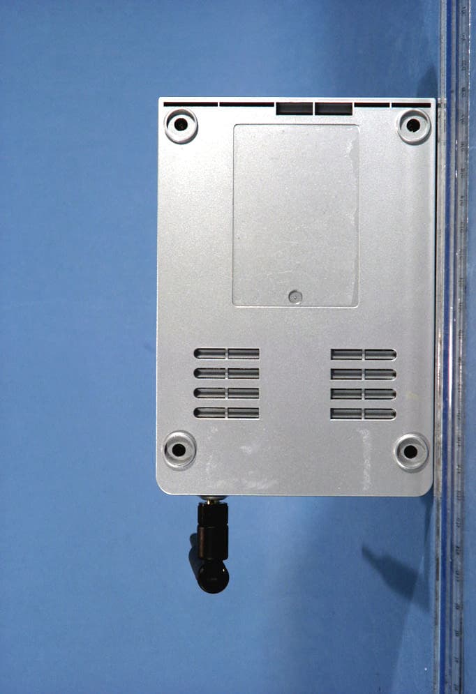
External Photos
OTC FCC ID: MKZTRIMAR EUT Photographs © 2005 PCTEST Lab. 802.11 A/B/G Wireless Ethernet NVLAP Lab Code: 100431-0 OTC FCC ID: MKZTRIMAR EUT Photographs © 2005 PCTEST Lab. 802.11 A/B/G Wireless Ethernet NVLAP Lab Code: 100431-0 OTC FCC ID: MKZTRIMAR EUT Photographs © 2005 PCTEST Lab. 802.11 A/B/G Wireless Ethernet NVLAP Lab Code: 100431-0
ID Label/Location Info
Digital Transmission System (DTS), 15.247 PCTEST LAB TEST REPORT 15.247 FCC Measurement Report Reviewed by: Quality Manager Filename: 0503140197 Test Dates: July 12-15, 2005 EUT Type: 802.11a/b/g Wireless Ethernet FCC ID: MKZTRIMAR Page 44 of 51 © 2005 PCTEST Engineering Laboratory, Inc. CONFIDENTIAL PROPERTY OF PCTEST EXHIBIT B – Labeling Requirements Sample Label & Location New Labeling Requirements Per 2.1074 & 15.19; Docket 95-19 The sample label shown below shall be permanently affixed at a conspicuous location on the device; instruction manual or pamphlet supplied to the user and be readily visible to the purchaser at the time of purchase. However, when the device is so small wherein placement of the label with specified statement is not practical, only the trade name, FCC ID, and the FCC logo must be displayed on the device per Section 15.19 (b)(2). Digital Transmission System (DTS), 15.247 PCTEST LAB TEST REPORT 15.247 FCC Measurement Report Reviewed by: Quality Manager Filename: 0503140197 Test Dates: July 12-15, 2005 EUT Type: 802.11a/b/g Wireless Ethernet FCC ID: MKZTRIMAR Page 45 of 51 © 2005 PCTEST Engineering Laboratory, Inc. CONFIDENTIAL PROPERTY OF PCTEST EXHIBIT B – Labeling Requirements (Cont.) Sample Label & Location FCC ID Label
Internal Photos
OTC FCC ID: MKZTRIMAR EUT Photographs © 2005 PCTEST Lab. 802.11 A/B/G Wireless Ethernet NVLAP Lab Code: 100431-0 OTC FCC ID: MKZTRIMAR EUT Photographs © 2005 PCTEST Lab. 802.11 A/B/G Wireless Ethernet NVLAP Lab Code: 100431-0 OTC FCC ID: MKZTRIMAR EUT Photographs © 2005 PCTEST Lab. 802.11 A/B/G Wireless Ethernet NVLAP Lab Code: 100431-0 OTC FCC ID: MKZTRIMAR EUT Photographs © 2005 PCTEST Lab. 802.11 A/B/G Wireless Ethernet NVLAP Lab Code: 100431-0 OTC FCC ID: MKZTRIMAR EUT Photographs © 2005 PCTEST Lab. 802.11 A/B/G Wireless Ethernet NVLAP Lab Code: 100431-0 OTC FCC ID: MKZTRIMAR EUT Photographs © 2005 PCTEST Lab. 802.11 A/B/G Wireless Ethernet NVLAP Lab Code: 100431-0
RF Exposure Info
© 2005 PCTEST Engineering Laboratory, Inc. RF Exposure Evaluation - Maximum Permissible Exposure (MPE) 1. Introduction This document attempts to prove the safety of radiation generated by RF devices to the human body. The limit for Maximum Permissible Exposure (MPE), specified in FCC 1.1210, is listed below. The power generated by this product is measured by a power meter. Through use of the Friis transmission formula and the maximum gain of the antenna, the distance from the product at which compliance with the MPE limit is achieved may be calculated. Alternatively, near field measurements may be performed to demonstrate compliance at a specific measurement distance. Near field probe: Wandel & Goltermann EMR-20. 2. RF Exposure Limit According to FCC 1.1310: the criteria listed in the following table shall be used to evaluate the environmental impact of human exposure to radio-frequency (RF) radiation as specified in 1.1307(b). LIMITS FOR MAXIMUM PERMISSIBLE EXPOSURE (MPE) Frequency Range (MHz) Electric Field Strength (V/m) Magnetic Field Strength (A/m) Power Density (mW/cm 2 ) Average Time (Minutes) (A) Limits For Occupational / Control Exposures 30-300 61.4 .163 1.0 6 300-1500 ... ... F/300 6 1500-100,000 ... ... 5 6 (B) Limits For General Population / Uncontrolled Exposure 30-300 27.5 .073 .2 30 300-1500 ... ... F/1500 30 1500-100,000 ... ... 1.0 30 F = Frequency in MHz 3. Friis Formula Friis transmission formula: Pd = (P out *G) / (4pr 2 ) Where: Pd = power density in mW/cm 2 (MPE limit) P out = output power to antenna in mW G = gain of antenna in linear scale p = 3.1416 r = distance between observation point and center of the radiator in cm Ref.: David K. Cheng, Field and Wave Electromagnetics, Second Edition, Page 640, Eq. (11.133) © 2005 PCTEST Engineering Laboratory, Inc. 4. EUT Operating Condition Software provided by the client enabled the EUT to transmit and receive data at lowest, middle, and highest channels individually. 5. Climate Condition The temperature and relative humidity: 22°C and 78% RH 6. Measurement Results Channel Channel Frequency (MHz) Output Power to Antenna (mW) Power Density (mW/cm 2 ) 6 2437 91.4 .018 64 5320 62.7 .012 1. Data taken with all transmitters operating simultaneously 7. Conclusion The device meets the mobile 20cm separation distance as specified in Section 2.1091 of the FCC Rules. An appropriate RF exposure compliance statement will be placed in the user’s manual.
Test Report
© 2005 PCTEST Engineering Laboratory, Inc. PCTEST ENGINEERING LABORATORY, INC. 6660 – B Dobbin Road • Columbia, MD 21045 • USA Telephone 410.290.6652 / Fax 410.290.6654 http://www.pctestlab.com (email: [email protected]) CERTIFICATE OF COMPLIANCE MANUFACTURER NAME & ADDRESS : DATE & LOCATION OF TESTING: OTC Wireless, Inc. Date(s) of Tests: July 12-15, 2005 48499 Milmont Drive Test Report S/N: 0503140197 Freemont, CA 94538 Test Site: PCTEST Lab, Columbia, MD FCC ID: MKZTRIMAR APPLICANT: OTC WIRELESS, INC. SUMMARY: Model No.: TRIMAR Equipment EUT Type: 802.11a/b/g Wireless Ethernet Max. Output Power: 19.50 dBm Peak Conducted (b) 19.60 dBm Peak Conducted (g) 19.55 dBm Peak Conducted (a) Frequency Range: 2412 - 2462 MHz (DSSS/OFDM) 5745 – 5825 MHz (OFDM) FCC Classification: Digital Transmission System (DTS) FCC Rule Part(s): Parts 15.247; ANSI C-63.4-2003 Test Device Serial No.: S/N: Pre-Production This equipment has been shown to be capable of compliance with the applicable technical standards as indicated in the measurement report and was tested in accordance with the measurement procedures specified in ANSI C-63.4-2003. I authorize and attest to the accuracy of data. All measurements reported herein were performed by me or were made under my supervision and are correct to the best of my knowledge and belief. I assume full responsibility for the completeness of these measurements and vouch for the qualifications of all persons taking them. PCTEST certifies that no party to this application has been denied the FCC benefits pursuant to Section 5301 of the Anti- Drug Abuse Act of 1988, 21 U.S.C. 862. Digital Transmission System (DTS), 15.247 PCTEST LAB TEST REPORT 15.247 FCC Measurement Report Reviewed by: Quality Manager Filename: 0503140197 Test Dates: July 12-15, 2005 EUT Type: 802.11a/b/g Wireless Ethernet FCC ID: MKZTRIMAR Page i of i © 2005 PCTEST Engineering Laboratory, Inc. CONFIDENTIAL PROPERTY OF PCTEST TABLE OF CONTENTS ATTESTATION STATEMENTS.............................................................................................................................1 FCC 15.247 MEASUREMENT REPORT COVER PAGE............................................................................................2 1.0 INTRODUCTION............................................................................................................................................3 1.1 EVALUATION PROCEDURE........................................................................................................................................................3 1.2 SCOPE...........................................................................................................................................................................................3 1.3 PCTEST TEST LOCATION.............................................................................................................................................................3 2.0 PRODUCT INFORMATION...........................................................................................................................4 2.1 EQUIPMENT DESCRIPTION........................................................................................................................................................4 2.2 ENCLOSURE.................................................................................................................................................................................4 2.3 EMI SUPPRESSION DEVICE(S)/MODIFICATIONS.......................................................................................................................4 3.0 DESCRIPTION OF TEST.................................................................................................................................5 3.1 CONDUCTED EMISSIONS..........................................................................................................................................................5 3.2 RADIATED EMISSIONS................................................................................................................................................................6 4.0 ANTENNA REQUIREMENTS..........................................................................................................................7 5.0 TEST EQUIPMENT CALIBRATION DATA.....................................................................................................8 EXHIBIT A. SUMMARY OF TEST RESULTS.................................................................................................................9 EXHIBIT A. 6dB BANDWIDTH MEAUREMENT (802.11A/B/G).....................................................................................10-18 EXHIBIT A. OUTPUT POWER MEASUREMENT (802.11A/B/G).....................................................................................19-21 EXHIBIT A. POWER SPECTRAL DENSITY...................................................................................................................22-27 EXHIBIT A. BANDEDGE............................................................................................................................................28-30 EXHIBIT A. RADIATED FUNDAMENTAL & HARMONIC MEASUREMENTS..................................................................31-39 EXHIBIT A. RADIATED RESTRICTED BAND MEASUREMENTS.....................................................................................40-41 EXHIBIT A. RECEIVER MODE LINE CONDUCTED & RADIATED SPURIOUS................................................................42-43 EXHIBIT B. LABELING REQUIREMENTS....................................................................................................................44-45 EXHIBIT C. BLOCK DIAGRAM/SCHEMATICS.............................................................................................................46 EXHIBIT D. OPERATIONAL DESCRIPTION..........................................................................…
Text truncated - open the document above for the full version.
Test Setup Photos
OTC FCC ID: MKZTRIMAR EUT Photographs © 2005 PCTEST Lab. 802.11 A/B/G Wireless Ethernet NVLAP Lab Code: 100431-0 OTC FCC ID: MKZTRIMAR EUT Photographs © 2005 PCTEST Lab. 802.11 A/B/G Wireless Ethernet NVLAP Lab Code: 100431-0 OTC FCC ID: MKZTRIMAR EUT Photographs © 2005 PCTEST Lab. 802.11 A/B/G Wireless Ethernet NVLAP Lab Code: 100431-0
Contact Information
Applicant
Jen Tsao(Program Director)
Technical Contact
PCTEST Engineering Lab., Inc.Randy Ortanez
[email protected]410-290-6652
6660-B Dobbin Road · Columbia, Maryland · United States
Test Firm
PCTEST Engineering Laboratory, Inc.Randy Ortanez
Technical Specifications
| # | Rule Parts | Frequency Range | Power Output |
|---|---|---|---|
| 2 | 15C | 5.75 GHz - 5.83 GHz | 90.00 mW |
Other Applications from OTC Wireless Inc
MKZWIJET11G
Apr 29, 2004802.11g Wireless Projector/ Monitor Adapter
Equipment Class
DTS - Digital Transmission System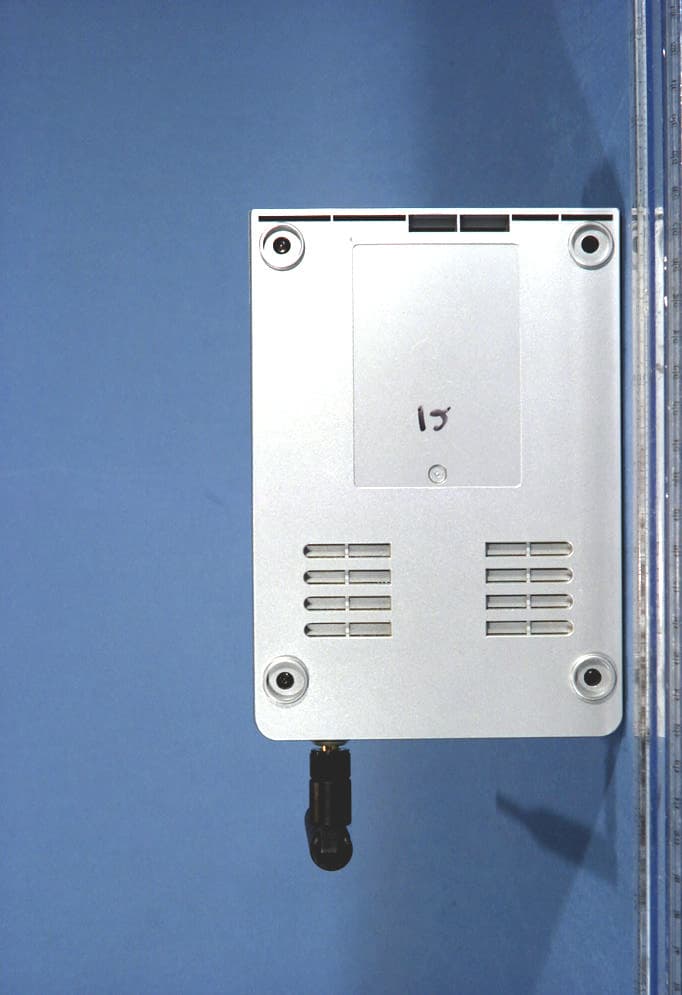
MKZWIJETVIDEO
Apr 29, 2004802.11g Wireless Projector/ Monitor Adapter
Equipment Class
DTS - Digital Transmission System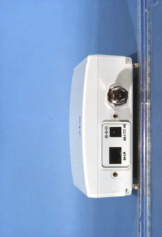
MKZAVCW11G682E
Oct 07, 2003Wireless Ethernet Adapter
Equipment Class
DTS - Digital Transmission System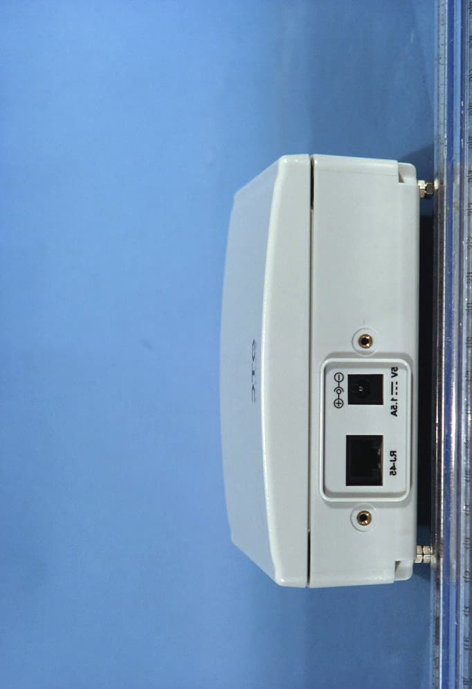
MKZAVCW11G682
Sep 29, 2003Wireless Ethernet Adapter
Equipment Class
DTS - Digital Transmission System
MKZWEA11G03682
Aug 27, 2003802.11g Wireless Ethernet Adapter
Equipment Class
DTS - Digital Transmission System