MKZEZY2411BT2.4GHz DS Spread Specturm Data Transceiver
OTC Wireless Inc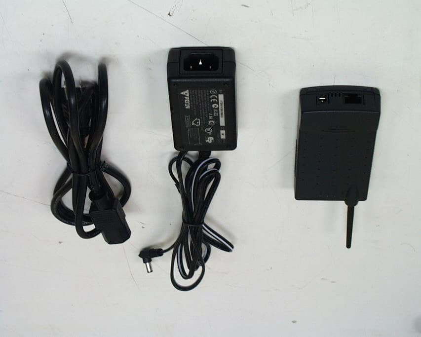
Click to zoom
Application Details
- Equipment Class
- DTS - Digital Transmission System
- Date of Grant
- Oct 27, 2002
- Application Purpose
- Original Equipment
- Date of Application
- Oct 27, 2002
- Equipment Note
- 2.4GHz DS Spread Specturm Data Transceiver
- Frequency Range
- 2412.00000000 - 2462.00000000
- Company
- OTC Wireless Inc
- Country
- United States
Documents & Files
Document Text
Text extracted from the exhibit documents filed with the FCC. Open a document above to read the original.
Users Manual
WiFi Wireless Ethernet Adapter AirEZY-2411-BT (ASR-102/ACR-201) User Guide AirEZY 2411 BT (ASR-102/ACR-201) Wireless Ethernet Adapter User’s Manual Copyright Information in this document is subject to change without notice. Complying with all applicable copyright laws is the responsibility of the user. No part of this document may be reproduced or transmitted in any form or by any means, electronic or mechanical, for any purpose, without the express written permission of the seller. If, however, your only means of access is electronic, permission to print one copy is hereby granted. The seller provides this documentation without warranty, term, or condition of any kind. The seller may make improvements or changes in the product(s) and/or the program(s) described in this documentation at any time. Other product and company names herein may be trademarks of their respective owners. Copyright 2001, 2002 OTC Wireless, Inc. All rights reserved. Revision: v1.12, 9/30/2002 i Table of Contents AirEZY-2411-BT (ASR-102/ACR-201) User’s Manual Chapter 1 INTRODUCTION 1 Data Sheet 2 Chapter 2 INSTALLATION 3 Installing the Hardware 3 Power 3 Ethernet connection 3 Status LEDs 3 Optional Hardware 5 Installing the Utility Software 6 System Requirement 6 Installation 6 Chapter 3 UTILITY SOFTWARE 7 Use the Utility Program 7 Overview of the Tabs 7 Configure AirEZY-2411-BT 7 Configure AirEZY-2411-BT as an Access Point (ASR-102) 8 Configure AirEZY-2411-BT as a Station (ACR-201) 12 Set up the Encryption 13 Obtain the Link Information 15 View the Packet Statistics 16 Uninstall the Utility Software 17 Chapter 4 TROUBLESHOOTING 18 Blank Pages Appear When Open the Utility Program 18 No Radio Link When Set Up As a Station 18 No Radio Link When Set Up As an AP 18 No Network Connection While the Radio Link is Good 19 Poor Link Quality 19 Radio Interference 20 Technical Support 20 Appendix A: LIMITED WARRANTY 21 Wireless LAN Hardware 21 Wireless LAN Software 21 Appendix B: REGULATROY COMPLIANCE 22 GLOSSARY 24 ii Chapter 1 INTRODUCTION AirEZY-2411-BT is an 802.11b compliant, or WiFi, radio with a 10-BaseT interface. Two features separate AirEZY-2411-BT from many other 802.11b-compliant radios. Firstly, this 802.11b-compliant (WiFi) radio can be configured as either a Station (ACR-201) or an AP (ASR-102). Secondly, when configured as a Station, the 10-BaseT interface affords it a true plug-and-play feature that is unavailable from any other 802.11b Station radios are based on either a PCMCIA or a USB interface and require the installation of a driver on the host computer. This driver-less feature also means that the operation of the radio is OS (operating system) independent. When configured as a Station, i.e. ACR-201, the driver-less feature enables wireless connectivity for any computing devices/systems installed with any OS (operating system), as long as an Ethernet communication port is available. Ethernet-equipped workstations in a corporate environment, for example, benefit greatly from this driver-less feature—the IT workforce has one less driver to worry when upgrading an OS or when salvaging an OS crash. Special computing/networking devices, such as printer servers, POS (point of sales) machines may not even have an easy way of installing a driver for a radio. When configured as an AP, i.e., ASR-102, AirEZY-2411-BT, offers a no-frill, seamless way of fitting a wireless network into an existing wired LAN infrastructure. It does not even require the assignment of an extra IP address. Existing wired-network resources such as DHCP, VPN, firewall, etc., reach across the ASR-102 to the client workstations with total transparency. Unlike many other 802.11b APs on the market, which offer network functions that are duplicative to the existing network, this AP simply wirelessly collects a group of workstations or other kinds of computing devices into the existing network—just like a hub. AirEZY-2411-BT has a compact form-factor that blends easily into a home/office environment. It also lends particularly well to portable applications. The specifications are given on the next page. 1 A Utility program is needed to pre-configure AirEZY-2411-BT prior to putting the radio in operation. And the Utility program can be used to monitor the communication condition once the radio is in operation. Once configured, the radio runs self-sufficiently without the aid of any driver program in the host computer connected to the radio. This Utility program therefore is intended to be, in most cases, just a tool for the network operators. An end user simply plugs the pre-configured radio into a host computer or a network device equipped with a RJ-45 receptacle without ever being expose to this Utility program. The Utility program is simple to install and easy to use through its graphic user interface. The details are described in Chapter 3. AirEZY-2411-BT (ASR-102/ACR-201) WiFi Radio Specifications Model AirEZY-2411-BT Standard 802.11 and 802.11b Host Interface Ethernet, 802.3, RJ-45 receptacle Frequency 2.4GHz – 2.495GHz RF Channels 11 channels (US, Canada), 13 channels (Europe), 13 channels (Japan) Transmission power 14dBm at antenna input typical Receiver sensitivity -80dBm @1e-5 BER typical Antenna Dipole antenna with ~2dBi gain Data Rate 11, 5.5, 2 or 1 Mbps fixed rate, or configured to automatic rate selection Modulation CCK, Direct Sequence Spread Spectrum Link Distance ~1200 ft in open space Network Types Support both the ad hoc mode and the infrastructure mode Data Encryption Support the standard 64-bit WEP and the optional 128-bit WEP Support User-enabled Dynamic WEP key generation and distribution Network Security Selectable levels of access control: SSID hidden in beacon, exact SSID match and MAC-address-based allowed-list; password protected AP configuration AC adapter Output: 5V, 2.6A; Input:100-120V, 50-60Hz, ~1.0A max Current consumption <480mA (max. reached in transmit-mode) LED Indicators 4: Power, Transmission, Receiving, …
Text truncated - open the document above for the full version.
ID Label/Location Info
PROPOSED FCC ID LABEL AND LOCATION OTC WIRELESS, INC. This device complies with Part 15 of the FCC Rules. Operation is subject to the following two conditions: (1) this device may not cause harmful interference, and (2) this device must accept any interference received, including interference that may cause undesired operation. FCC ID: MKZEZY2411BT FCC ID LABEL
Test Report
FCC ID :MKZEZY2411BT Report No.:510-9110-002F Page 1 of 40 Industrial Technology Research Institute Electronics Research & Service Organization Bldg. 17, 195-4 Sec. 4, Chung Hsing Rd., Chutung,Hsinchu, 310 Taiwan,Republic Of China TEL : 886-3-5917069 FAX : 886-3-5825720 ELECTROMAGNETIC COMPATIBILITY TEST REPORT Company : OTC Wireless, INC. Address : 48507 Milmont Drive Fremont, CA 94538, USA Product name : Ethernet Dongle Model name : ASR-102 // ACR-201 Date Received : OCT. 1, 2002 Date Tested : OCT. 1-3, 2002 Note: The two models names are just for marketing issue. The all other data is the same. MEASUREMENT REQUIREMENT USED : 47 CFR Part 15, Subpart B and Subpart C (Section 15.247), ANSI C63.4-1992 WE HEREBY CERTIFY THAT: The measurements shown in the attachment were made in accordance with the procedures indicated, and the energy emitted by the equipment was found to be within the limits applicable. We assume full responsibility for the accuracy and completeness of these measurements and vouch for the qualifications of all persons taking them. Notes : 1. This report will be invalid if duplicated or photocopied in part. 2. This report refers only to the specimen(s) submitted to test, and is invalid as seperately used. 3. This report is invalid without examination stamp and signature of this institute. 4. The tested specimen(s) will be preserved for thirty days from the data issued. 5. The report must not be used to claim product certification, approval, or endorsement by NVLAP, NIST, or any agency of the federal government. FCC ID :MKZEZY2411BT Report No.:510-9110-002F Page 2 of 40 Industrial Technology Research Institute Electronics Research & Service Organization Bldg. 17, 195-4 Sec. 4, Chung Hsing Rd., Chutung,Hsinchu, 310 Taiwan,Republic Of China TEL : 886-3-5917069 FAX : 886-3-5825720 TABLE OF CONTENTS TITLEPAGE NO. 1. GENERAL INFORMATION ...................................................................................................... 4 1.1 GENERAL STATEMENT ................................................................................................ 4 1.2 GENERAL DESCRIPTION OF EUT & POWER ............................................................ 4 1.3 DESCRIPTION OF PERIPHERALS ................................................................................ 5-6 1.4 EUT & PERIPHERALS SETUP DIAGRAM ................................................................... 7 1.5 EUT OPERATING CONDITION ..................................................................................... 7 1.6 DESCRIPTION OF TEST SITE........................................................................................ 8 1.7 SUMMARY OF TEST RESULTS ..................... ......... .................. ...... ... ... ......8 2. CONDUCTED POWERLINE TEST .......................................................................................... 9 2.1 TEST EQUIPMENTS........................................................................................................ 9 2.2 TEST SETUP ..................................................................................................................... 9 2.3 CONDUCTED POWER LINE EMISSION LIMIT .......................................................... 10 2.4 TEST PROCEDURE ......................................................................................................... 10 2.5 UNCERTAINTY OF CONDUCTED EMISSION............................................................ 10 2.6 CONDUCTED RF VOLTAGE MEASUREMENT.......................................................... 12 2.7 PHOTOS OF CONDUCTION TEST ................................................................................ 12 3. RADIATED EMISSION TEST................................................................................................... 13 3.1 TEST EQUIPMENTS........................................................................................................ 13 3.2 TEST SETUP ..................................................................................................................... 13 3.3 RADIATION LIMIT ......................................................................................................... 14 3.4 TEST PROCEDURES ....................................................................................................... 15 3.5 UNCERTAINTY OF RADIATED EMISSION................................................................ 15 3.6 RADIATED RF NOISE MEASUREMENT ..................................................................... 16-24 3.7 PHOTOS OF OPEN SITE ................................................................................................. 25-26 4. 6dB BANDWIDTH MEASUREMENT ...................................................................................... 27 4.1 TEST EQUIPMENTS........................................................................................................ 27 4.2 TEST SETUP ..................................................................................................................... 27 4.3 LIMITS OF 6dB BANDWIDTH MEASUREMENT ....................................................... 27 4.4 TEST PROCEDURE ......................................................................................................... 27 4.5 UNCERTAINTY OF CONDUCTED EMISSION............................................................ 27 4.6 TEST RESULTS................................................................................................................28 4.7 PHOTO OF 6DB BANDWIDTH MEASURERMENT .................................................... 29 5. MAXIMUM PEAK OUTPUT POWER...................................................................................... 30 5.1 TEST EQUIPMENTS........................................................................................................ 30 5.2 TEST SETUP ..................................................................................................................... 30 5.3…
Text truncated - open the document above for the full version.
Test Setup Photos
FCC ID :MKZEZY2411BT Report No.:510-9110-002F Page 12 of 40 Industrial Technology Research Institute Electronics Research & Service Organization Bldg. 17, 195-4 Sec. 4, Chung Hsing Rd., Chutung,Hsinchu, 310 Taiwan,Republic Of China TEL : 886-3-5917069 FAX : 886-3-5825720 2.7 PHOTOS OF CONDUCTION TEST FCC ID :MKZEZY2411BT Report No.:510-9110-002F Page 25 of 40 Industrial Technology Research Institute Electronics Research & Service Organization Bldg. 17, 195-4 Sec. 4, Chung Hsing Rd., Chutung,Hsinchu, 310 Taiwan,Republic Of China TEL : 886-3-5917069 FAX : 886-3-5825720 3.7 PHOTOS OF OPEN SITE FCC ID :MKZEZY2411BT Report No.:510-9110-002F Page 26 of 40 Industrial Technology Research Institute Electronics Research & Service Organization Bldg. 17, 195-4 Sec. 4, Chung Hsing Rd., Chutung,Hsinchu, 310 Taiwan,Republic Of China TEL : 886-3-5917069 FAX : 886-3-5825720 3.7 PHOTOS OF OPEN SITE
Contact Information
Applicant
Jen Tsao(Program Director)
Test Firm
Compliance Certification Services Inc.Paul Liau
Technical Specifications
| # | Rule Parts | Frequency Range | Power Output |
|---|---|---|---|
| 1 | 15C | 2.41 GHz - 2.46 GHz | 45.00 mW |
Other Applications from OTC Wireless Inc
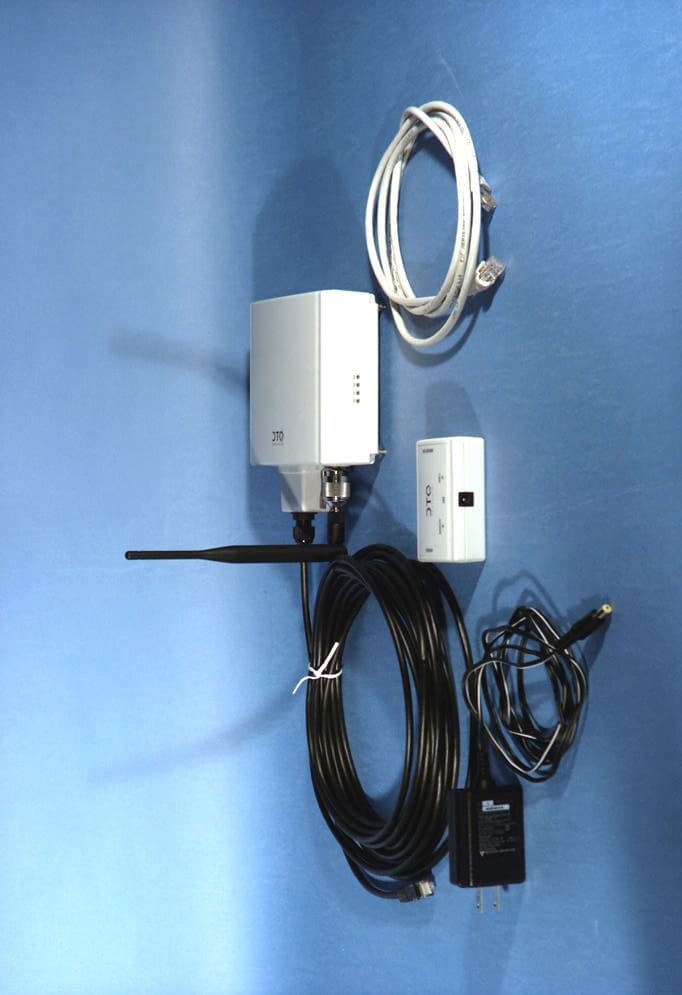
MKZTRIMAR
Sep 08, 2005802.11a/b/g Wireless Ethernet Transceiver
Equipment Class
DTS - Digital Transmission System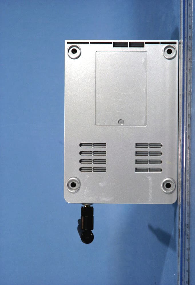
MKZWIJET11G
Apr 29, 2004802.11g Wireless Projector/ Monitor Adapter
Equipment Class
DTS - Digital Transmission System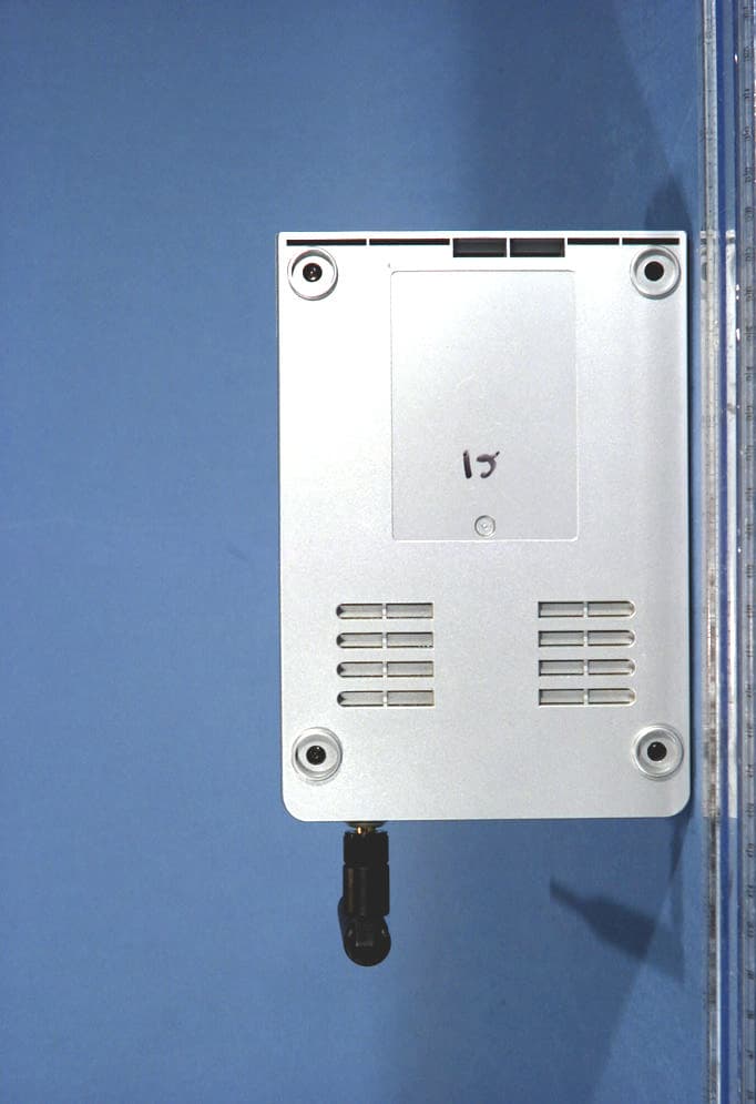
MKZWIJETVIDEO
Apr 29, 2004802.11g Wireless Projector/ Monitor Adapter
Equipment Class
DTS - Digital Transmission System
MKZAVCW11G682E
Oct 07, 2003Wireless Ethernet Adapter
Equipment Class
DTS - Digital Transmission System
MKZAVCW11G682
Sep 29, 2003Wireless Ethernet Adapter
Equipment Class
DTS - Digital Transmission System