MKZWEA11G03682802.11g Wireless Ethernet Adapter
OTC Wireless Inc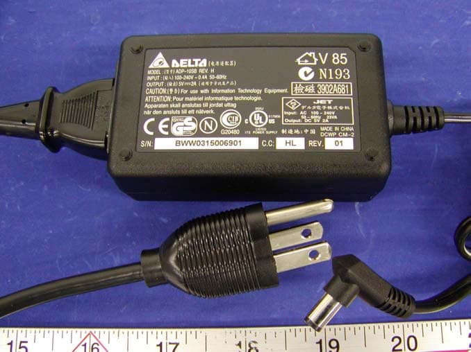
Click to zoom
Application Details
- Equipment Class
- DTS - Digital Transmission System
- Date of Grant
- Aug 27, 2003
- Application Purpose
- Original Equipment
- Date of Application
- Aug 27, 2003
- Equipment Note
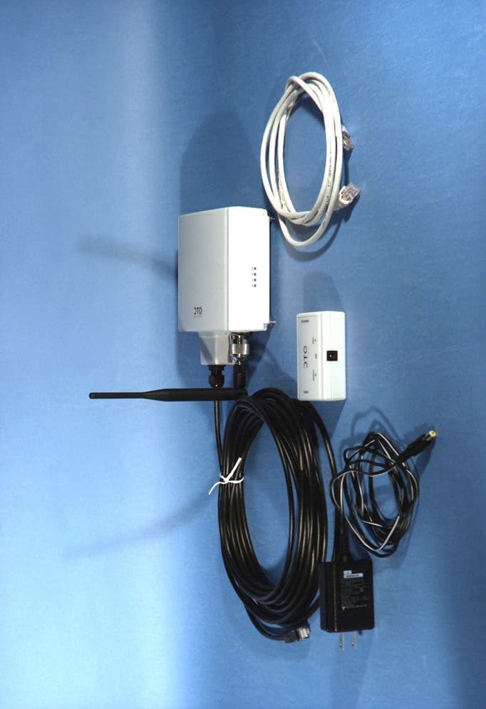
- 802.11g Wireless Ethernet Adapter
- Frequency Range
- 2412.00000000 - 2462.00000000
- Company
- OTC Wireless Inc
- Country
- United States
Documents & Files
Document Text
Text extracted from the exhibit documents filed with the FCC. Open a document above to read the original.
Users Manual
ACR-201-G 802.11g Wireless Ethernet Adapter Technical Manual www.otcwireless.com ACR-201-G Technical Manual ii ACR-201-G Wireless Ethernet Adapter Technical Manual Copyright Information in this document is subject to change without notice. Complying with all applicable copyright laws is the responsibility of the user. No part of this document may be reproduced or transmitted in any form or by any means, electronic or mechanical, for any purpose, without the express written permission of the seller. If, however, your only means of access is electronic, permission to print one copy is hereby granted. The seller provides this documentation without warranty, term, or condition of any kind. The seller may make improvements or changes in the product(s) and/or the program(s) described in this documentation at any time. Other product and company names herein may be trademarks of their respective owners. Copyright 2001-2003 OTC Wireless, Inc. All rights reserved. Rev 3.00c August 11, 2003 ACR-201-G Technical Manual iii Table of Contents ACR-201-G Technical Manual Chapter 1 Introduction..................................................................................................... 1 ACR-201-G Radio .......................................................................................................... 2 Specifications ..................................................................................................................2 Chapter 2 Installation....................................................................................................... 3 Safety Statements............................................................................................................ 3 Installing the Hardware................................................................................................... 3 Power........................................................................................................................... 3 Ethernet Connection...................................................................................................... 3 Status LED’s................................................................................................................. 3 System Requirements for Web-based Utility program ................................................... 6 Chapter 3 Web-Based Utility Software........................................................................... 7 Use the Web-Based Utility Program............................................................................... 7 Overview of the Web Pages............................................................................................ 7 Basic Information............................................................................................................ 8 Wireless......................................................................................................................... 10 Security ......................................................................................................................... 10 Advance ........................................................................................................................12 Admin ........................................................................................................................... 14 Help............................................................................................................................... 17 Chapter 4 Troubleshooting ............................................................................................ 18 No Page Displayed When Accessing the Web-based Utility ....................................... 18 No Radio Link............................................................................................................... 18 No Network Connection While the Radio Link is Good .............................................. 18 Poor Link Quality ......................................................................................................... 19 Radio Interference......................................................................................................... 19 TFTP Timeouts ............................................................................................................. 20 Settings Appear not to be Modified .............................................................................. 20 Technical Support ......................................................................................................... 20 Appendix A: Limited Warranty .................................................................................... 21 Appendix B: Regulatory Compliance .......................................................................... 22 ACR-201-G Technical Manual 1 Chapter 1 Introduction ACR-201-G is an 802.11g compliant radio with a 100-BaseT interface that acts as a Wireless Adapter. What separates the ACR-201-G from many other 802.11g-compliant radios is that its 100-BaseT interface affords a true plug-and-play feature that is unavailable from any other 802.11g Station radios that are based on either a PCMCIA or a USB interface and require the installation of a driver on the host device. This driver-free feature also means that the operation of the radio is OS (operating system) independent. The driver-free feature enables wireless connectivity for any computing devices/systems with any OS (operating system), as long as the device has an Ethernet communication port available. Ethernet-equipped workstations in a corporate environment, for example, benefit greatly from this driver-less feature—the IT workforce has one less driver to worry when upgrading an OS or when salvaging an OS crash. Special computing/networking devices, such as printer servers, POS (point of sales) machines may not even have an easy way of installing a driver for a radio. In addition to supporting the connection of a single computer or device to an 802.11g Access Point in…
Text truncated - open the document above for the full version.
Attestation Statements
Bay Area Compliance Laboratory Corp. 230 Commercial Street Sunnyvale, CA 94085 Tel: (408) 732-9162 Fax: (408) 732-9164 www.baclcorp.com 27 August 2003 Re: response to evaluation report R0307211, question #5 We have measured the distance to the antenna both from the base to the closest point of the antenna on two of the thinnest laptops available, namely the Sony Vaio and the Toshiba Portege. On both models, due to the normally recommended and published configuration and due to the more conveniently expected user location during reasonable and normal use, the device antenna would be at least 20 cm from the body. Hans Mellberg Engineering Manager
External Photos
EXHIBIT C - EUT EXTERNAL PHOTOGRAPHS EUT – Chassis Top View EUT – Chassis Rear View EUT – Chassis Bottom View AKII Power Adapter View DELTA Power Adapter View
ID Label/Location Info
EXHIBIT A - FCC ID LABEL INFORMATION Proposed FCC ID Label Specifications: Text is black or white in color and is left justified. Labels are silk- screened and shall be “permanently affixed” at a conspicuous location on the EUT. Proposed Label Location on EUT Bottom Side of EUT/FCC ID Label FCC ID: MKZWEA11G03682 This device complies with Part 15 o the FCC Rules. Operation is subject to the following two conditions: (1) this device may not cause harmful interference, and (2) this device must accept any interference received, including interference that may cause undesired operation. 2.1875" 1.0"
Internal Photos
EXHIBIT C - EUT INTERNAL PHOTOGRAPHS EUT – Chassis Cover Off View EUT – Component View 1 EUT – Component View 2 EUT – Component View with Antenna EUT – Solder View EUT – Solder View with Antenna EUT – Transceiver Component View EUT – Transceiver Component with Shield Removed View EUT –Transceiver Solder View 1 EUT – Transceiver Solder View 2 Antenna Connection View
Test Report
Note: This test report is specially limited to the above client company and product model only. It may not be duplicated without prior written consent of Bay Area Compliance Laboratory Corporation. This report must not be used by the client to claim product endorsement by NVLAP or any agency of the U.S. Government. FCC PART 15 SUBPART C EMI MEASUREMENT AND TEST REPORT For OTC Wireless, Inc 48507 Milmont Drive Fremont, CA 94538 FCC ID: MKZWEA11G03682 2003-08-13 This Report Concerns: Original Report Equipment Type: 802.11g Wireless Ethernet Adapter Test Engineer: Ling Zhang / Report No.: R0307211 Test Date: 2003-07-24 Reviewed By: Ming Jing / Prepared By: Bay Area Compliance Laboratory Corporation (BACL) 230 Commercial Street Sunnyvale, CA 94085 Tel: (408) 732-9162 Fax: (408) 732 9164 OTC Wireless, Inc FCC ID: MKZWEA11G03682 Report # R0307211Rpt.doc Page 2 of 50 FCC Part 15.247 Test Report TABLE OF CONTENTS 1 - GENERAL INFORMATION..................................................................................................................................4 1.1 PRODUCT DESCRIPTION FOR EQUIPMENT UNDER TEST (EUT) .......................................................................4 1.2 OBJECTIVE.............................................................................................................................................................4 1.3 RELATED SUBMITTAL(S)/GRANT(S).......................................................................................................................4 1.4 TEST METHODOLOGY............................................................................................................................................4 1.5 TEST FACILITY.......................................................................................................................................................5 1.6 TEST EQUIPMENT LIST...........................................................................................................................................5 1.7 SUPPORT EQUIPMENT LIST AND DETAILS..............................................................................................................6 1.8 EXTERNAL I/O CABLING LIST AND DETAILS.........................................................................................................6 1.9 POWER SUPPLY INFORMATION...............................................................................................................................6 2 - SYSTEM TEST CONFIGURATION.....................................................................................................................7 2.1 JUSTIFICATION.......................................................................................................................................................7 2.2 EUT EXERCISE SOFTWARE....................................................................................................................................7 2.3 SPECIAL ACCESSORIES...........................................................................................................................................7 2.4 SCHEMATICS / BLOCK DIAGRAM...........................................................................................................................7 2.5 EQUIPMENT MODIFICATIONS.................................................................................................................................7 2.6 CONFIGURATION OF TEST SYSTEM.........................................................................................................................8 2.7 TEST SETUP BLOCK DIAGRAM...............................................................................................................................8 3 - SUMMARY OF TEST RESULTS..........................................................................................................................9 4 - CONDUCTED OUTPUT POWER MEASUREMENT......................................................................................10 4.1 STANDARD APPLICABLE......................................................................................................................................10 4.2 MEASUREMENT PROCEDURE................................................................................................................................10 4.3 TEST EQUIPMENT.................................................................................................................................................10 4.4 MEASUREMENT RESULT......................................................................................................................................10 5 – 6 DB BANDWIDTH ..............................................................................................................................................14 5.1 STANDARD APPLICABLE......................................................................................................................................14 5.2 MEASUREMENT PROCEDURE................................................................................................................................14 5.3 TEST EQUIPMENT.................................................................................................................................................14 5.4 MEASUREMENT RESULT......................................................................................................................................14 6 - SPURIOUS EMISSION AT ANTENNA TERMINAL.......................................................................................18 6.1 STANDARD APPLICABLE......................................................................................................................................18 6.2 MEASUREMENT PROCEDURE................................................................................................................................18 6.3 TEST EQUIPMENT..................................................................…
Text truncated - open the document above for the full version.
Test Report
OTC Wireless, Inc FCC ID: MKZWEA11G03682 Report # R0307211Rpt.doc Page 18 of 50 FCC Part 15.247 Test Report 6 - SPURIOUS EMISSION AT ANTENNA TERMINAL 6.1 Standard Applicable According to §15.209 (f) and §15.33(a), in some cases the emissions from an intentional radiator must be measured to beyond the tenth harmonic of the highest fundamental frequency designed to be emitted by the intentional radiator because of the incorporation f a digital device. If measurements above the tenth harmonic are so required, the radiated emissions above the tenth harmonic shall comply with the general radiated emission limits applicable to the incorporated digital device, as shown in §15.109 and as based on the frequency of the emission being measured, or, except for emissions contained in the restricted frequency bands shown in §15.205, the limit on spurious emissions specified for the intentional radiator, whichever is the higher limit. 6.2 Measurement Procedure 1. Check the calibration of the measuring instrument (SA) using either an internal calibrator or a known signal from an external generator. 2. Position the EUT as shown in figure 4 without connection to measurement instrument. Turn on the EUT and connect its antenna terminal to measurement instrument via a low loss cable. Then set it to any one measured frequency within its operating range, and make sure the instrument is operated in its linear range. 3. Set the SA on Max-Hold Mode, and then keep the EUT in transmitting mode. Record all the signals from each channel until each one has been recorded. 4. Set the SA on View mode and then plot the result on SA screen. 5. Repeat above procedures until all frequencies measured were complete. 6.3 Test Equipment Manufacturer Model No. Serial No. Calibration Due Date HP 8564E Spectrum Analyzer 2003-12-06 6.4 Measurement Result Please refer to following pages for plots of spurious emission. OTC Wireless, Inc FCC ID: MKZWEA11G03682 Report # R0307211Rpt.doc Page 19 of 50 FCC Part 15.247 Test Report OTC Wireless, Inc FCC ID: MKZWEA11G03682 Report # R0307211Rpt.doc Page 20 of 50 FCC Part 15.247 Test Report OTC Wireless, Inc FCC ID: MKZWEA11G03682 Report # R0307211Rpt.doc Page 21 of 50 FCC Part 15.247 Test Report OTC Wireless, Inc FCC ID: MKZWEA11G03682 Report # R0307211Rpt.doc Page 22 of 50 FCC Part 15.247 Test Report OTC Wireless, Inc FCC ID: MKZWEA11G03682 Report # R0307211Rpt.doc Page 23 of 50 FCC Part 15.247 Test Report OTC Wireless, Inc FCC ID: MKZWEA11G03682 Report # R0307211Rpt.doc Page 24 of 50 FCC Part 15.247 Test Report OTC Wireless, Inc FCC ID: MKZWEA11G03682 Report # R0307211Rpt.doc Page 25 of 50 FCC Part 15.247 Test Report OTC Wireless, Inc FCC ID: MKZWEA11G03682 Report # R0307211Rpt.doc Page 26 of 50 FCC Part 15.247 Test Report OTC Wireless, Inc FCC ID: MKZWEA11G03682 Report # R0307211Rpt.doc Page 27 of 50 FCC Part 15.247 Test Report OTC Wireless, Inc FCC ID: MKZWEA11G03682 Report # R0307211Rpt.doc Page 28 of 50 FCC Part 15.247 Test Report OTC Wireless, Inc FCC ID: MKZWEA11G03682 Report # R0307211Rpt.doc Page 29 of 50 FCC Part 15.247 Test Report OTC Wireless, Inc FCC ID: MKZWEA11G03682 Report # R0307211Rpt.doc Page 30 of 50 FCC Part 15.247 Test Report OTC Wireless, Inc FCC ID: MKZWEA11G03682 Report # R0307211Rpt.doc Page 31 of 50 FCC Part 15.247 Test Report 7 - PEAK POWER SPECTRAL DENSITY 7.1 Standard Applicable According to §15.247 (d), digitally modulated systems, the peak power spectral density conducted from the intentional radiator to the antenna shall not be greater than 8 dBm in any 3 kHz band during any time interval of continuous transmission. 7.2 Measurement Procedure 1. Check the calibration of the measuring instrument using either an internal calibrator or a known signal from an external generator. 2. Position the EUT was set without connection to measurement instrument. Turn on the EUT and connect its antenna terminal to measurement instrument via a low loss cable. Then set it to any one measured frequency within its operating range, and make sure the instrument is operated in its linear range. 3. Adjust the center frequency of SA on any frequency be measured and set SA to 6MHz span mode. And then, set RBW and VBW of spectrum analyzer to proper value. 4. Repeat above procedures until all frequencies measured were complete. 7.3 Test Equipment Manufacturer Model No. Serial No. Calibration Due Date HP 8564E Spectrum Analyzer 2003-12-06 7.4 Measurement Results Frequency (MHz) Peak Power Spectral Density (dBm) Standard (dBm) Result 2412 -12.50 ≤ 8 Compliant 2437 -12.67 ≤ 8 Compliant 802.11b 2462 -13.00 ≤ 8 Compliant 2412 -20.00 ≤ 8 Compliant 2437 -25.83 ≤ 8 Compliant 802.11g 2462 -26.50 ≤ 8 Compliant 7.5 Plot of Peak Power Spectral Density Please refer to following pages for plots of peak power spectral density. OTC Wireless, Inc FCC ID: MKZWEA11G03682 Report # R0307211Rpt.doc Page 32 of 50 FCC Part 15.247 Test Report OTC Wireless, Inc FCC ID: MKZWEA11G03682 Report # R0307211Rpt.doc Page 33 of 50 FCC Part 15.247 Test Report OTC Wireless, Inc FCC ID: MKZWEA11G03682 Report # R0307211Rpt.doc Page 34 of 50 FCC Part 15.247 Test Report
Test Report
OTC Wireless, Inc FCC ID: MKZWEA11G03682 Report # R0307211Rpt.doc Page 35 of 50 FCC Part 15.247 Test Report 8 - 100 KHZ BANDWIDTH OF BAND EDGES 8.1 Standard Applicable According to §15.247(c), in any 100 kHz bandwidth outside the frequency bands in which the spread spectrum intentional radiator is operating, the radio frequency power that is produced by the intentional radiator shall be at least 20 dB below that in the 100 kHz bandwidth within the band that contains the highest level of the desired power, based on either an RF conducted or a radiated measurement. In addition, radiated emissions which fall in the restricted bands, as defined in §15.205(a), must also comply with the radiated emission limits specified in §15.209(a) see §15.205(c)). 8.2 Measurement Procedure 1. Check the calibration of the measuring instrument using either an internal calibrator or a known signal from an external generator. 2. Position the EUT without connection to measurement instrument. Turn on the EUT and connect its antenna terminal to measurement instrument via a low loss cable. Then set it to any one measured frequency within its operating range, and make sure the instrument is operated in its linear range. 3. Set both RBW and VBW of spectrum analyzer to 100 kHz with a convenient frequency span including 100kHz bandwidth from band edge. 4. Measure the highest amplitude appearing on spectral display and set it as a reference level. Plot the graph with marking the highest point and edge frequency. 5. Repeat above procedures until all measured frequencies were complete. 8.3 Test Equipment Manufacturer Model No. Serial No. Calibration Due Date HP 8564E Spectrum Analyzer 2003-12-06 8.4 Measure Results Please refer to following pages for plots of band edge. OTC Wireless, Inc FCC ID: MKZWEA11G03682 Report # R0307211Rpt.doc Page 36 of 50 FCC Part 15.247 Test Report OTC Wireless, Inc FCC ID: MKZWEA11G03682 Report # R0307211Rpt.doc Page 37 of 50 FCC Part 15.247 Test Report OTC Wireless, Inc FCC ID: MKZWEA11G03682 Report # R0307211Rpt.doc Page 38 of 50 FCC Part 15.247 Test Report 9 - ANTENNA REQUIREMENT 9.1 Standard Applicable For intentional device, according to § 15.203, an intentional radiator shall be designed to ensure that no antenna other than that furnished by the responsible party shall be used with the device. And according to § 15.247 (1), if transmitting antennas of directional gain greater than 6 dBi are used the power shall be reduced by the amount in dB that the directional gain of the antenna exceeds 6 dBi. 9.2 Antenna Connected Construction The gain of dipole antenna used for transmitting is 2 dBi, and the antenna connector is uniquely designed with no consideration of replacement. OTC Wireless, Inc FCC ID: MKZWEA11G03682 Report # R0307211Rpt.doc Page 39 of 50 FCC Part 15.247 Test Report 10 - SPURIOUS RADIATED EMISSION 10.1 Measurement Uncertainty All measurements involve certain levels of uncertainties. The factors contributing to uncertainties are spectrum analyzer, cable loss, antenna factor calibration, antenna directivity, antenna factor variation with height, antenna phase center variation, antenna factor frequency interpolation, measurement distance variation, site imperfections, mismatch (average), and system repeatability. Based on NIS 81, The Treatment of Uncertainty in EMC Measurements, the best estimate of the uncertainty of a radiation emissions measurement at BACL is + 4.0 dB. 10.2 EUT Setup The radiated emission tests were performed in the open area 3-meter test site, using the setup in accordance with the ANSI C63.4-1992. The specification used was the FCC 15 Subpart C limits. The spacing between the peripherals was 10 centimeters. External I/O cables were draped along the edge of the test table and bundle when necessary. The EUT was connected with 120Vac/60Hz power source. 10.3 Spectrum Analyzer Setup According to FCC Rules, 47 CFR §15.33 (a) (1), the system was tested to 25GHz. During the radiated emission test, the spectrum analyzer was set with the following configurations: Frequency Range RBW Video B/W Below 30MHz 10kHz 10kHz 30 – 1000MHz 100kHz 100kHz Above 1000MHz 1MHz 1MHz 10.4 Test Procedure For the radiated emissions test, the Host PC system power cord was connected to the AC floor outlet since the power supply used in the EUT did not provide an accessory power outlet. Maximizing procedure was performed on the six (6) highest emissions to ensure EUT compliance is with all installation combinations. All data was recorded in the peak detection mode. Quasi-peak readings was performed only when an emission was found to be marginal (within -4 dBμV of specification limits), and are distinguished with a "Qp" in the data table. OTC Wireless, Inc FCC ID: MKZWEA11G03682 Report # R0307211Rpt.doc Page 40 of 50 FCC Part 15.247 Test Report 10.5 Corrected Amplitude & Margin Calculation The Corrected Amplitude is calculated by adding the Antenna Factor and Cable Factor, and subtracting the Amplifier Gain from the Amplitude reading. The basic equation is as follows: Corr. Ampl. = Indicated Reading + Antenna Factor + Cable Factor - Amplifier Gain The “Margin” column of the following data tables indicates the degree of compliance with the applicable limit. For example, a margin of -7dBμV means the emission is 7dBμV below the maximum limit for Subpart C. The equation for margin calculation is as follows: Margin = Corr. Ampl. – Subpart C Limit 10.6 Test Equipment Manufacturer Model No. Serial No. Calibration Due Date HP 8564E Spectrum Analyzer 2003-12-06 10.7 Summary of Test Results According to the data in section 10.8, the EUT complied with the FCC Title 47, Part 15, Subpart C, section 15.205, 15.207 and 15.247, and had the worst margin of: For802.11b: -12.6 dB at 7236.00 MHz in the Vertical polarization, Low Channel -12.9 dB at 7311.00 MHz in the Vertical polarization, Middle Channel -13.1 dB at 7386.00 MHz in the Vertical polarization, High Channel -2.1 dB at 480.02 MHz in the Vertical p…
Text truncated - open the document above for the full version.
Test Setup Photos
EXHIBIT B - TEST SETUP PHOTOGRAPHS Conducted Emission - Front View Conducted Emission - Side View Radiated Emission - Front View Radiated Emission - Rear View
Contact Information
Applicant
Jen Tsao(Program Director)
Test Firm
Bay Area Compliance LaboratoryJohn Chan
Technical Specifications
| # | Rule Parts | Frequency Range | Power Output |
|---|---|---|---|
| 1 | 15C | 2.41 GHz - 2.46 GHz | 42.00 mW |
Other Applications from OTC Wireless Inc
MKZTRIMAR
Sep 08, 2005802.11a/b/g Wireless Ethernet Transceiver
Equipment Class
DTS - Digital Transmission System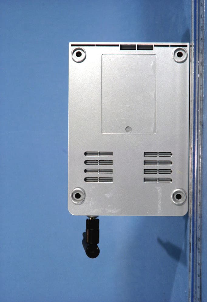
MKZWIJET11G
Apr 29, 2004802.11g Wireless Projector/ Monitor Adapter
Equipment Class
DTS - Digital Transmission System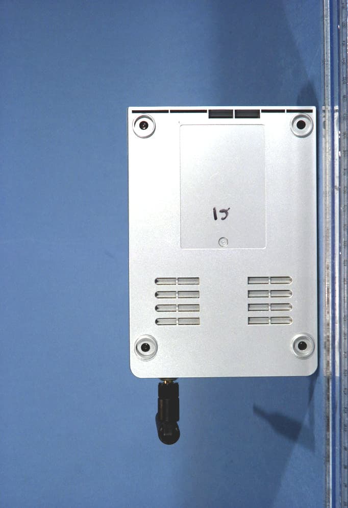
MKZWIJETVIDEO
Apr 29, 2004802.11g Wireless Projector/ Monitor Adapter
Equipment Class
DTS - Digital Transmission System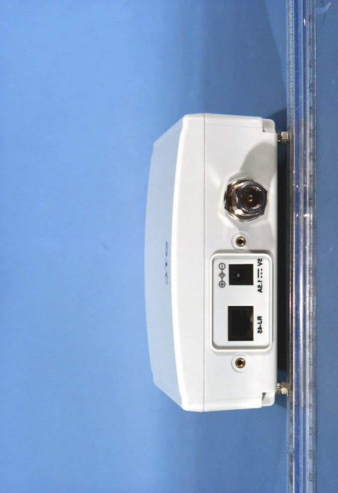
MKZAVCW11G682E
Oct 07, 2003Wireless Ethernet Adapter
Equipment Class
DTS - Digital Transmission System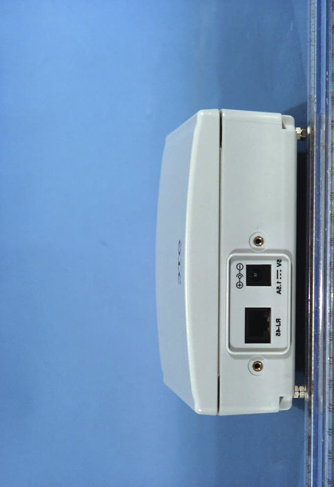
MKZAVCW11G682
Sep 29, 2003Wireless Ethernet Adapter
Equipment Class
DTS - Digital Transmission System