MNISI481Wireless Transmitter
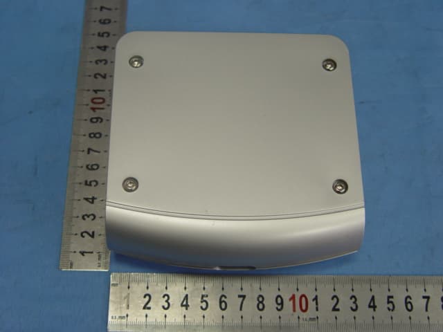
Sharper Image, The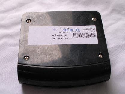
Click to zoom
Application Details
- Equipment Class
- DXX - Part 15 Low Power Communication Device Transmitter
- Date of Grant
- Aug 15, 2004
- Application Purpose
- Original Equipment
- Date of Application
- Aug 15, 2004
- Equipment Note
- Wireless Transmitter
- Frequency Range
- 913.00000000 - 916.10000000
- Company
- Sharper Image, The
- Country
- United States
Documents & Files
Document Text
Text extracted from the exhibit documents filed with the FCC. Open a document above to read the original.
Users Manual
INCLUDES IMPORTANT SAFETY INFORMATION READ ALL INSTRUCTIONS BEFORE USING THIS APPLIANCE SAVE THESE INSTRUCTIONS SI494 Instructions Wireless Stereo Speaker System ® PRODUCT ILLUSTRATION Dear Sharper Image Customer, Thank you for your purchase of a Sharper Image Design product. We appreciate your business very much. Please accept my personal assurance of your complete satisfaction with this product’s quality and performance. We offer generous return privileges and excellent warranties on all our products. For more than 25 years, The Sharper Image has shared the fun of discovering innovative products that make life easier and more enjoyable. We’ve been in business a long time because we are an exciting place to shop and - just as importantly - we strive to deliver great customer service that exceeds your expectations. Enjoy your purchase! Respectfully, Richard Thalheimer Founder, Chairman and Chief Executive Offi cer Shop our complete Internet catalog. n Important Safety Instructions READ AND SAVE THESE INSTRUCTIONS Important Safety Instructions READ AND SAVE THESE INSTRUCTIONS Important Safety Instructions Important Safety Instructions Important Safety Instructions Connecting the Transmitter Connect the transmitter AC Adapter to the transmitter DC power input jack and plug the transmitter AC Adapter into any 110-120V wall outlet. Connecting to a stereo receiver Connect the mini plug on the end of the Audio Input Cable to the mini jack on the “Y” Cable Adapter Connect the RCA plugs on the other end of the “Y” Cable Adapter to the audio outputs of a stereo receiver/amp or other audio source. Connecting to a television Connect the mini plug on the end of the Audio Input Cable to the mini jack on the “Y” Cable Adapter. Connect the dual RCA plugs on the other end of the “Y” Cable Adapter to the RCA-type audio outputs of a TV. WARNING: DO NOT connect the RCA plugs of the “Y” Cable Adapter to a speaker output on the audio source. If you use the speaker output of an audio source to connect the transmitter, you will permanently damage the transmitter. It is designed to work with RCA-type line/variable outputs only. Connecting the Speakers and Subwoofer Stereo Speakers Ensure the Power button is turned OFF. Insert the power cord from a Speaker AC Adapter(9V 1000ma) into the Speaker dc Power Input Jack. lug the Speaker AC Adapter into any standard wall outlet. Repeat for another speaker. Note: Be sure to use the AC adapter rated 120V AC Input and 9V DC output. Subwoofer Ensure the Power button is turned OFF. Plug another end of the power cord into any standard wall outlet. Transmitter Confi guration urn ON the Audio Source (i.e. Stereo Receiver, TV, etc.) so that you can hear sound from the source. Switch ON the transmitter by turn the Power Switch to “ON”. The Power Indicator should be lit. Pivot the Antenna to the upright, vertical position. Set the frequency control wheel to its midpoint. Set the volume control wheel to its midpoint. Woofer/Speaker Confi guration Press the power button to switch ON the woofer, the Power Indicator should lit Turn the Tuning Control Wheel until the woofer is tuned to the signal from the transmitter. If the audio source is on and operating, you should now hear sound. Adjust volume as desired. Set the Left/Mono/Right Switch accordingly (SI492 Speakers only) Repeat the above process for speakers. Note: Interference in the form of static and/or distortion can sometimes be heard. If this occurs, confi rm the transmitter/ speaker adjustments of fi ne tune. If the problem persists, refer to the ADDITIONAL INFORMATION section of this manual. Additional Information If there is no sound coming from the system: Confi rm that the Transmitter AC Adapter is fully inserted into the wall outlet and the power cord from the AC adapter is fi rmly connected to the Transmitter Power Input Jack Confi rm that the Speaker AC Adapter is fully inserted into the wall outlet and the power cord from the AC Adapter is fi rmly connected to the Speaker Power Input Jack. Confi rm that the Woofer power cord is fully inserted into the wall outlet . Confi rm that the Transmitter, Speakers and Woofer are switched ON. (i.e. The Power Indicator Light should be lit) Check that the audio source (stereo, TV, etc) is turned on and providing sound as it normally should. Check that the audio source, transmitter, woofer and speaker volume are turned up. Additional Information If there is poor sound coming from the system: Check that the Woofer/Speaker Power Indicator Light is illumi- nated Blue. If not, press the Power button. Check that the antenna of the transmitter is in the upright position. Change the position of the Transmitter Frequency Control Wheel to change the operating frequency, Then readjust the speaker Tuning Control Wheel until you heard a clear sound. Try changing the physical location of the transmitter. Locate it as high and free of obstruction as possible. Avoid placing directly on the top of a TV, computer if possible. Try moving the transmitter, woofer and speakers closer togeth- er. Sending the signal through certain materials, such as wall, glass, tile, and metal, can decrease the effective transmitting distance of the system. Try changing the antenna position, particularly if you think you may be near maximum transmitting range. Statement of FCC compliance Model: SI494 WARNING: Changes or modifi cations to this unit not expressly approved by the party responsible for compliance could void the user’s authority to operate the equipment. This equipment has been tested and found to comply with the limits for a Class B digital device, pursuant to Part 15 of the FCC Rules. These limits are designed to provide reasonable protection against harmful interference in a residential installation. This equipment generates, uses, and can radiate radio frequency energy and, if not installed and used in accordance with the instructions, may cause harmful interference to radio communications. However, th…
Text truncated - open the document above for the full version.
External Photos
PHOTOGRAPH OF THE PRODUCT FRONT VIEW OF THE PRODUCT REAR VIEW OF THE PRODUCT
ID Label/Location Info
WIRELESS TRANSMITTER MODEL: SI481 PATENTS PENDING, MADE IN CHINA DESIGNED IN USA BY SAN FRANCISCO FCC ID: MNISI481 ADAPTER: DC 12V 100mA SI481 Transmitter Box(BACK PLATE) 12/7/04 rev. 3 Back Plate SIZE :30mm x 57mm 1.6mm 1.95mm
Internal Photos
PHOTOGRAPH OF THE PRODUCT INNER CIRCUIT TOP VIEW INNER CIRCUIT BOTTOM VIEW
Operational Description
FCC ID: MNISI481 Circuit Description The 915MHz crystal oscillator drives the base of Q1 the final/buffer amplifier. The modulation provided by IC. The output of Q1 has the matching network consisting of C37 and L3 that limit the harmonic content and effect the proper coupling of the antenna to the output stage. Antenna, Ground and Power Source There is no antenna. There is no external ground connection. The ground is only that of the printed circuit board. Electric current is supplied by a 12V dc.
Test Report
香 港 標 準 及 檢 定 中 心 Hong Kong Standards and Testing Centre Date : 2004-07-29 TEST REPORT Page 1 of 17 No. : HM151338 This report shall not be reproduced unless with prior written approval from the Hong Kong Standards and Testing Centre. 香港新界大埔工業村大宏街10號 10 Dai Wang Street, Taipo Industrial Estate, N.T., Hong Kong Tel: (852) 2666 1888 Fax: (852) 2664 4353 Homepage: www.hkstc.org E-mail: [email protected] For full text of “Conditions of Issuance of Test Report”, please refer to overleaf or refer to the website of STC: www.hkstc.org (the section “Application and Quotation”). Applicant: THE SHARPER IMAGE 650 Davis Street, San Francisco, CA94111, U.S.A. Description of Samples: Model name: Wireless Transmitter Model no.: SI481 Brand name: THE SHARPER IMAGE FCC ID: MNISI481 Date Samples Received: 2004-06-01 Date Tested: 2004-06-12 Investigation Requested: FCC Part 15 Subpart C Conclusions: The submitted product COMPLIED with the requirements of Federal Communications Commission [FCC] Rules and Regulations Part 15. The tests were performed in accordance with the standards described above and on Section 2.2 in this Test Report. Remarks: ---- K C Lee, EMC for Chief Executive 香 港 標 準 及 檢 定 中 心 Hong Kong Standards and Testing Centre Date : 2004-07-29 TEST REPORT Page 2 of 17 No. : HM151338 香港新界大埔工業村大宏街10號 10 Dai Wang Street, Taipo Industrial Estate, N.T., Hong Kong Tel: (852) 2666 1888 Fax: (852) 2664 4353 Homepage: www.hkstc.org E-mail: [email protected] For full text of “Conditions of Issuance of Test Report”, please refer to overleaf or refer to the website of STC: www.hkstc.org (the section “Application and Quotation”). CONTENT: Cover Page 1 of 17 Content Page 2-3 of 17 1.0 General Details 1.1 Test Laboratory Page 4 of 17 1.2 Applicant Details Page 4 of 17 Applicant HKSTC Code Number for Applicant Manufacturer 1.3 Equipment Under Test [EUT] Page 5 of 17 Description of EUT operation 1.4 Date of Order Page 5 of 17 1.5 Submitted Sample Page 5 of 17 1.6 Test Duration Page 5 of 17 1.7 Country of Origin Page 5 of 17 1.8 Additional Information of EUT Page 6 of 17 2.0 Technical Details 2.1 Investigations Requested Page 7 of 17 2.2 Test Standards and Results Summary Page 7 of 17 3.0 Test Results 3.1 Emission Page 8-12 of 17 香 港 標 準 及 檢 定 中 心 Hong Kong Standards and Testing Centre Date : 2004-07-29 TEST REPORT Page 3 of 17 No. : HM151338 香港新界大埔工業村大宏街10號 10 Dai Wang Street, Taipo Industrial Estate, N.T., Hong Kong Tel: (852) 2666 1888 Fax: (852) 2664 4353 Homepage: www.hkstc.org E-mail: [email protected] For full text of “Conditions of Issuance of Test Report”, please refer to overleaf or refer to the website of STC: www.hkstc.org (the section “Application and Quotation”). Appendix A List of Measurement Equipment Page 13 of 17 Appendix B Photographs Page 14-17 of 17 香 港 標 準 及 檢 定 中 心 Hong Kong Standards and Testing Centre Date : 2004-07-29 TEST REPORT Page 4 of 17 No. : HM151338 香港新界大埔工業村大宏街10號 10 Dai Wang Street, Taipo Industrial Estate, N.T., Hong Kong Tel: (852) 2666 1888 Fax: (852) 2664 4353 Homepage: www.hkstc.org E-mail: [email protected] For full text of “Conditions of Issuance of Test Report”, please refer to overleaf or refer to the website of STC: www.hkstc.org (the section “Application and Quotation”). 1.0 General Details 1.1 Test Laboratory The Hong Kong Standards and Testing Centre Ltd. EMC Laboratory 10 Dai Wang Street, Taipo Industrial Estate New Territories, Hong Kong 1.2 Applicant Details Applicant THE SHARPER IMAGE 650 Davis Street, San Francisco, CA94111, U.S.A HKSTC Code Number for Applicant OEE001 Manufacturer OEM Electronics Ltd. Unit 1002-1004, 10/F., Kwai Cheong Centre, 40-52 Kwai Cheong Road, Kwai Chung 香 港 標 準 及 檢 定 中 心 Hong Kong Standards and Testing Centre Date : 2004-07-29 TEST REPORT Page 5 of 17 No. : HM151338 香港新界大埔工業村大宏街10號 10 Dai Wang Street, Taipo Industrial Estate, N.T., Hong Kong Tel: (852) 2666 1888 Fax: (852) 2664 4353 Homepage: www.hkstc.org E-mail: [email protected] For full text of “Conditions of Issuance of Test Report”, please refer to overleaf or refer to the website of STC: www.hkstc.org (the section “Application and Quotation”). 1.3 Equipment Under Test [EUT] Description of Sample Product: Wireless Transmitter Manufacturer: OEM Electronics Ltd. Brand Name: THE SHARPER IMAGE Model Number: SI481 Input Voltage: 12Vd.c. With Adaptor The AC/DC Adaptor used for the tests was a "Winstar" adaptor: Model Number: NA-12, Input: 100-120/220-240Va.c., Ouput: 3-15Vd.c. 1200mA max. 1.3.1 Description of EUT Operation The Equipment Under Test (EUT) is The Sharper Image, Wireless Transmitter. The transmitter is a 2 button transmitter. The EUT continues to transmit while button is being pressed, Modulation by LCR. 1.4 Date of Order 2004-06-01 1.5 Submitted Sample(s): 1 Sample per model 1.6 Test Duration 2004-06-12 1.7 Country of Origin China 香 港 標 準 及 檢 定 中 心 Hong Kong Standards and Testing Centre Date : 2004-07-29 TEST REPORT Page 6 of 17 No. : HM151338 香港新界大埔工業村大宏街10號 10 Dai Wang Street, Taipo Industrial Estate, N.T., Hong Kong Tel: (852) 2666 1888 Fax: (852) 2664 4353 Homepage: www.hkstc.org E-mail: [email protected] For full text of “Conditions of Issuance of Test Report”, please refer to overleaf or refer to the website of STC: www.hkstc.org (the section “Application and Quotation”). 1.8 Additional Information of EUT Submitted Not Available User Manual Part List Circuit Diagram Printed Circuit Board [PCB] Layout Block diagram FCC ID Label 香 港 標 準 及 檢 定 中 心 Hong Kong Standards and Testing Centre Date : 2004-07-29 TEST REPORT Page 7 of 17 No. : HM151338 香港新界大埔工業村大宏街10號 10 Dai Wang Street, Taipo Industrial Estate, N.T., Hong Kong Tel: (852) 2666 1888 Fax: (852) 2664 4353 Homepage: www.hkstc.org E-mail: [email protected] For full text of “Conditions of Issuance of Test Report”, please refer to overleaf or refer to the website of STC: www.hkstc.org (the section “Application and Quotation”). 2.0 Technical Details 2.1 Investigations Requested Perform ElectroMagnetic Interference measurement in acc…
Text truncated - open the document above for the full version.
Test Setup Photos
TEST SET UP PHOTOGRAPH OF THE PRODUCT MEASUREMENT OF RADIATED EMISSION TEST SET UP MEASUREMENT OF CONDUCTED EMISSION TEST SET UP
Contact Information
Applicant
Chuck E Taylor
Test Firm
Hong Kong Standards & Testing Cen.Wilson Wong
Technical Specifications
| # | Rule Parts | Frequency Range | Power Output |
|---|---|---|---|
| 1 | 15C | 913 MHz - 916.1 MHz | - |
Other Applications from Sharper Image, The
MNISI494
May 22, 2005Wireless Stereo Speaker System Transmitter
Equipment Class
DXX - Part 15 Low Power Communication Device Transmitter
MNI-SI367
Oct 17, 2004SECURITY/REMOTE CONTROL TRANSMITTER
Equipment Class
DSC - Part 15 Security/Remote Control Transmitter
MNI-SI567A
Feb 10, 2002Object Finder Receiver
Equipment Class
CRR - Superregenerative Receiver
MNI-SI567
Feb 10, 2002Object Finder's
Equipment Class
DSC - Part 15 Security/Remote Control Transmitter
MNI-SI685
Sep 03, 2001Remote Control Toy Transmitter
Equipment Class
DXX - Part 15 Low Power Communication Device Transmitter