MQ4-MBR-1100Android TV Dongle
Abocom Systems Inc
Click to zoom
Application Details
- Equipment Class
- JBC - Part 15 Class B Computing Device/Personal Computer
- Date of Grant
- Sep 21, 2014
- Application Purpose
- Original Equipment
- Date of Application
- Sep 21, 2014
- Equipment Note
- Android TV Dongle
- Company
- Abocom Systems Inc
- Country
- Taiwan
Documents & Files
Document Text
Text extracted from the exhibit documents filed with the FCC. Open a document above to read the original.
Users Manual
MBR-1100 User Manual i Contents 1. Introduction 1 1.1. Package contents 1 1.2. Physical view 2 2. Hardware Operation 2 2.1. How to connect the player 2 3. Software Operation 3 3.1. System boot-up 3 3.2. Settings 3 4. Technical Data 5 4.1. Specifications 5 IAdea Limited Warranty 6 1 1. Introduction This document describes the hardware of the MBR-1100 and terms of IAdea Limited Warranty. 1.1. Package contents NOT INCLUDED: A USB mouse is required for system setup ATTACH the wireless antenna as shown below, and then screw antenna clockwise onto the post. Media Player Unit HDMI extension cord Ethernet cable Wi-Fi Antenna AC Adapter (with select power plug) ADB USB cable 2 1.2. Physical view Physical features (left to right in above illustration) HDMI 1.4 connector for digital video and audio combined output ADB , Android debug console port Micro USB for power adapter Power and Status LED indicator Ethernet port for network content update Micro SD card slot USB ports for USB content update and configuration S/W Reset button to perform factory reset Wireless antenna post 2. Hardware Operation 2.1. How to connect the player 1 Connect player and display via HDMI port with extension cord Power jack Network Display Power adapter Ethernet / wireless Video Extension cord 3 2 Plug in Ethernet cable (optional) 3 Connect player to power via micro USB port with power adapter 3. Software Operation 3.1. System boot-up 1 After the power is supplied for approximately 40 seconds, the booting animation will be displayed on screen as shown below : 2 The boot-up process takes approximately 75 seconds to complete. After boot-up completes, player will stay in Basic settings menu if no content service has been configured (i.e. first boot-up for brand new unit or after a factory reset). If you have already set content into the player, contents will play back automatically after 15 seconds after boot-up. 3.2. Settings You must attach a USB mouse to the player to configure settings. If the player has touch screen, then the USB mouse is not required, and all the click action can be replaced by tap action. Troubleshooting Tips for media players 1The status LED lights up, but no video is displayed on screen Ensure that your video cable (HDMI) is securely connected. Check if your monitor is turned on and the correct video input source is selected 4 (Fig. 2.2.1) Basic settings: – Network, Time zone and Content. Each time the Basic settings menu is entered, playback will automatically begin after 15 seconds if content services have been previously set. Auto playback can be canceled by clicking on the button before the countdown ends. User is able to enter Advanced Settings by clicking the Advanced button. To enter the menu system at any time during playback, plug in a USB mouse and hold the left mouse key in the corner area as shown below for 10 seconds. If the player has touch screen, then tapping and holding in the corner areas for 10 seconds would also bring you to the menu. *Player will ask for password if password has been configured. 5 4. Technical Data 4.1. Specifications MBR-1100 Video format support POPAI Screen Media Standards S6 (MPEG-1 SIF, 3Mbps CBR) S7 (MPEG-1 480p, 10Mbps CBR) S8 (MPEG-1 720p, 15Mbps CBR) S9 (MPEG-2 480p, 6Mbps CBR) S10 (MPEG-2 720p, 12Mbps CBR) S11 (MPEG-4 AVC, 480p, 6Mbps CBR) S12 (MPEG-4 AVC, 720p, 10Mbps CBR) E4 (VC-1/WMV9, MP@ML, 720p) E7 (MPEG-4 ASP, 480p, 10Mbps CBR) E8 (MPEG-4 AVC, 1080p, 10Mbps CBR) Image format support POPAI Screen Media Standards S1 (JPEG 480p baseline) S2 (JPEG 720p baseline) S3 (JPEG 1080p baseline) E1 (PNG 24bpp+alpha, 480p) E2 (PNG 24bpp+alpha, 720p) E3 (PNG 24bpp+alpha, 1080p) Audio codec support POPAI Screen Media Standards S4 (MPEG L2 audio) S5 (MP3 audio, 320Kbps) Dynamic content W3C HTML5 (HTML, CSS, JavaScript) W3C SMIL 3.0 instructions (sub-set) Physical I/O connectors HDMI 1.4 USB 2.0 x 2 RJ45 Ethernet port Wi-Fi antenna port Micro USB for ADB Local storage 8 GB on-board flash memory (up to 6 hrs of typical 720p video @ 3 Mbps) Micro SD card expansion slot Accessories HDMI extension cord Ethernet cable Wi-Fi antenna ADB USB cable Power requirement 5V 2A DC Power consumption* 6 W Environmental Operating temperature: 0 – 40° C / 32 – 104° F Humidity: 5 – 85% @ 40° C / 32 – 104° F non-condensing Dimensions 107 x 68 x 25.3 mm (4.21 X 2.68 X 1 inches) Weight 108.1 g 0.24 lbs Safety UL / CE certified power supplies Certifications CE / FCC / RoHS Warranty One-year limited parts & labor 6 IAdea Limited Warranty For Media Player Devices Applicable to IAdea product models: MBR-1100 1. IAdea provides, unless extended through optional service programs, one (1) year of limited warranty on its applicable product models listed above. The applicable product must be purchased through an authorized IAdea reseller. Subject to the conditions of this warranty, IAdea will perform necessary service on the product without charge for parts or labor if, in the opinion of IAdea, the product is found to be faulty within the warranty period. IAdea’s sole warranty and obligation will be to repair or replace (at it sole discretion) such products that require warranty during the applicable warranty period in accordance with these conditions. If the product is found to be in correct working order, then IAdea reserves the right to charge you for its time and materials costs. 2. This warranty only applies if the product has been under normal use and reasonable care (in the opinion of IAdea). The warranty covers normal usage for which the unit was originally supplied and does not cover damage, malfunction or failure resulting from use of incorrect voltages, unauthorized installation, accident, misuse, neglect, build-up of dirt or dust, abuse, power surge problems, thunderstorm activity, tampering or repair by unauthorized persons (including unauthorized alterations), unauthorized maintenance, exposure to abnormally corrosive conditions or any foreign object or matte…
Text truncated - open the document above for the full version.
External Photos
Abocom Systems Inc Model: MBR-1100 REPORT NO.: STR14078217I-1 FCC PART 15.247 EXHIBIT 2 - EUT EXTERNAL PHOTOGRAPHS EUT View 1 EUT View 2 Abocom Systems Inc Model: MBR-1100 REPORT NO.: STR14078217I-1 FCC PART 15.247 EUT View 3 EUT View 4 Abocom Systems Inc Model: MBR-1100 REPORT NO.: STR14078217I-1 FCC PART 15.247 EUT View 5 EUT View 6 Abocom Systems Inc Model: MBR-1100 REPORT NO.: STR14078217I-1 FCC PART 15.247 EUT View 6 Antenna View
ID Label/Location Info
Abocom Systems Inc Model: MBR-1100 REPORT NO.: STR14078217I-1 FCC PART 15.247 EXHIBIT 1 - PRODUCT LABELING Proposed FCC ID Label Format FCC ID: MQ4-MBR-1100 This device complies with Part 15 of the FCC Rules. Operation is subject to the following two conditions: (1) This device may not cause harmful interference, and (2) this device must accept any interference received, including interference that may cause undesired operation. Specifications: Text is Black in color and justified. Labels are printed in indelible ink on permanent adhesive silk-screened onto the EUT or shall be affixed at a conspicuous location on the EUT. Proposed Label Location on EUT FCC ID Label Location
ID Label/Location Info
Abocom Systems Inc Model: MBR-1100 REPORT NO.: STR14078217I-1 FCC PART 15.247 EXHIBIT 1 - PRODUCT LABELING Proposed FCC ID Label Format FCC ID: MQ4-MBR-1100 This device complies with Part 15 of the FCC Rules. Operation is subject to the following two conditions: (1) This device may not cause harmful interference, and (2) this device must accept any interference received, including interference that may cause undesired operation. Specifications: Text is Black in color and justified. Labels are printed in indelible ink on permanent adhesive silk-screened onto the EUT or shall be affixed at a conspicuous location on the EUT. Proposed Label Location on EUT FCC ID Label Location
Internal Photos
Abocom Systems Inc Model: MBR-1100 REPORT NO.: STR14078217I-1 FCC PART 15.247 EXHIBIT 2 - EUT INTERNAL PHOTOGRAPHS EUT Housing and Board View Solder Board-Component View 1 Abocom Systems Inc Model: MBR-1100 REPORT NO.: STR14078217I-1 FCC PART 15.247 Solder Board-Component View 2 Solder Board-Component View 3 Abocom Systems Inc Model: MBR-1100 REPORT NO.: STR14078217I-1 FCC PART 15.247 Solder Board-Component View 4
Test Report
Abocom Systems Inc Model: MBR-1100 REPORT NO.: STR14078217I-2 PAGE 1 OF 22 FCC PART 15B FCC Part 15B Measurement and Test Report For Abocom Systems Inc No.77, Yu-Yih Rd., Chu-Nan, Miao-Lih County 35059, Taiwan R.O.C. FCC ID: MQ4-MBR-1100 Test Rule(s): FCC Part 15 Subpart B Product Description: Android TV Dongle Tested Model: MBR-1100 Report No.: STR14078217I-2 Tested Date: 2014-07-23 to 2014-08-27 Issued Date: 2014-08-27 Tested By: Jason Su / Engineer Reviewed By: Lahm Peng / EMC Manager Approved & Authorized By: Jandy so / PSQ Manager Prepared By: Shenzhen SEM.Test Technology Co., Ltd. 1/F, Building A, Hongwei Industrial Park, Liuxian 2nd Road, Bao'an District, Shenzhen, P.R.C.(518101) Tel.: +86-755-33663308 Fax.: +86-755-33663309 Website: www.semtest.com.cn Note: This test report is limited to the above client company and the product model only. It may not be duplicated without prior permitted by Shenzhen SEM.Test Technology Co., Ltd. Abocom Systems Inc Model: MBR-1100 REPORT NO.: STR14078217I-2 PAGE 2 OF 22 FCC PART 15B TABLE OF CONTENTS 1. GENERAL INFORMATION ................................................................................................................................... 3 1.1 PRODUCT DESCRIPTION FOR EQUIPMENT UNDER TEST (EUT) ............................................................................... 3 1.2 TEST STANDARDS ................................................................................................................................................... 4 1.3 TEST METHODOLOGY ............................................................................................................................................. 4 1.4 TEST FACILITY ....................................................................................................................................................... 4 1.5 EUT SETUP AND OPERATION MODE ...................................................................................................................... 5 2. SUMMARY OF TEST RESULTS ........................................................................................................................... 6 3. CONDUCTED EMISSIONS .................................................................................................................................... 7 3.1 MEASUREMENT UNCERTAINTY .............................................................................................................................. 7 3.2 TEST EQUIPMENT LIST AND DETAILS ..................................................................................................................... 7 3.3 TEST PROCEDURE ................................................................................................................................................... 7 3.4 BASIC TEST SETUP BLOCK DIAGRAM ..................................................................................................................... 7 3.5 ENVIRONMENTAL CONDITIONS .............................................................................................................................. 8 3.6 SUMMARY OF TEST RESULTS/PLOTS ...................................................................................................................... 8 3.7 CONDUCTED EMISSIONS TEST DATA ...................................................................................................................... 8 4. RADIATED EMISSIONS ....................................................................................................................................... 15 4.1 MEASUREMENT UNCERTAINTY ............................................................................................................................ 15 4.2 TEST EQUIPMENT LIST AND DETAILS ................................................................................................................... 15 4.3 TEST PROCEDURE ................................................................................................................................................. 15 4.4 TEST RECEIVER SETUP ......................................................................................................................................... 16 4.5 CORRECTED AMPLITUDE & MARGIN CALCULATION ............................................................................................ 16 4.6 ENVIRONMENTAL CONDITIONS ............................................................................................................................ 16 4.7 SUMMARY OF TEST RESULTS/PLOTS .................................................................................................................... 16 Abocom Systems Inc Model: MBR-1100 REPORT NO.: STR14078217I-2 PAGE 3 OF 22 FCC PART 15B 1. GENERAL INFORMATION 1.1 Product Description for Equipment Under Test (EUT) Client Information Applicant: Abocom Systems Inc Address of applicant: No.77, Yu-Yih Rd., Chu-Nan, Miao-Lih County 35059,Taiwan R.O.C. Manufacturer: Abocom Systems Inc Address of manufacturer: No.77, Yu-Yih Rd., Chu-Nan, Miao-Lih County 35059,Taiwan R.O.C. General Description of EUT Product Name: Android TV Dongle Trade Name: / Model No.: MBR-1100 Adding Model(s): XMP-6200 Note: The test data is gathered from a production sample, provided by the manufacturer. The appearance of others models listed in the report is different from main-test model MBR-1100, but the circuit and the electronic construction do not change, declared by the manufacturer. Technical Characteristics of EUT Rated Voltage: AC 120V Adapter:DC5.35V Rated Current: 2A Rated Power: / Power Adapter Model: PSAI10R-050Q Lowest Internal Frequency: 32.768KHz Highest Internal Frequency: 1GHz Classification of ITE: Class B Abocom Systems Inc Model: MBR-1100 REPORT NO.: STR14078217I-2 PAGE 4 OF 22 FCC PART 15B 1.2 Test Standards The following report is prepared on behalf of the Abocom Systems Inc in accordance with Part 2, Subpart J, and Part 15, Subparts A and B of the Feder…
Text truncated - open the document above for the full version.
Test Setup Photos
Abocom Systems Inc Model: MBR-1100 REPORT NO.: STR14078217I-2 FCC PART 15B EXHIBIT 4 - TEST SETUP PHOTOGRAPHS Conducted Emission Test Setup Radiation Emission Test Setup Abocom Systems Inc Model: MBR-1100 REPORT NO.: STR14078217I-2 FCC PART 15B
Contact Information
Applicant
Harry Huang(Manager)
Test Firm
Shenzhen SEM.Test Technology Co., Ltd.Jandy So
Technical Specifications
| # | Rule Parts | Frequency Range | Power Output |
|---|---|---|---|
| 1 | 15B | - | - |
Other Applications from Abocom Systems Inc

MQ4WM5208
Oct 27, 2015802.11b/g/n Module
Equipment Class
DTS - Digital Transmission System
MQ4AM7221
Mar 18, 20152T2R 802.11b/g/n/ac Module
Equipment Class
DTS - Digital Transmission System
MQ4PLW72
Mar 18, 201511ac WiFi Extender Smart Plug / 11ac WiFi Extender
Equipment Class
NII - Unlicensed National Information Infrastructure TX
MQ4CB1522M
Sep 22, 2014IP Camera
Equipment Class
DTS - Digital Transmission System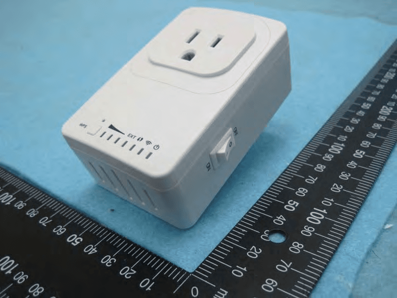
MQ4PLW52
Jul 07, 201411n WiFi Extender Smart Plug
Equipment Class
DTS - Digital Transmission System