MQDMIL538RRemote Control Toy
Million Industrial Ltd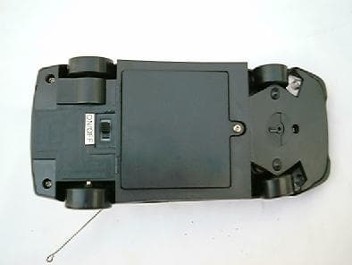
Click to zoom
Application Details
- Equipment Class
- DXT - Part 15 Low Power Transceiver, Rx Verified
- Date of Grant
- Mar 02, 2004
- Application Purpose
- Original Equipment
- Date of Application
- Mar 02, 2004
- Equipment Note
- Remote Control Toy
- Frequency Range
- 26.69000000 - 26.69000000
- Company
- Million Industrial Ltd
- Country
- Hong Kong
Documents & Files
Document Text
Text extracted from the exhibit documents filed with the FCC. Open a document above to read the original.
Users Manual
JP-46338 Remote Car Instruction Manual FEATURES: CAR LENGTH: 180 MM FUNCTIONS: Forward, Turn left, Turn right, Stop Reverse left, Reverse right, Headlights. BATTERY INSTALLATION • Open the battery compartment cover at the bottom of the car, install four "AA" nickel Cadmium or Alkaline batteries, whereas, for the transmitter, use one 9V battery. • Make sure the polarity (+ and -) is correct. • Use Nickel Cadmium or Alkaline batteries instead of the ordinary type can achieve the best performance for your car. OPERATION • Extend the antenna of the controller to full length. • For maximum range of control always keep the antennae straight up and hold the transmitter at upright position. • Set the power switch of car to "ON" position. • Use two hands to operate the control sticks. On the left hand side, the level control the car to go forward and backward, whereas, the right hand side lever controls it's forward and backward turning actions. • Attempt to operate the forward/backward action, and turning action at the same time. • Plug the earphone into the earphone jack. You can receive the voice nearby the car, This is called "SPY". • If the car does not go straight, adjust the 'ALIGNMENT' at the bottom of the car. • When not in use, switch OFF the car. If you do not intend to use the car for a long time, remove the batteries, weak or dead batteries can leak damaging chemicals. • For best performance, use alkaline batteries. HINTS • Since the unit operates on 27 MHz, you may experience interference from CB radio, which is in the same band of frequencies. Under such conditions, better change location or wait until interference ceases. Also two or more R/C cars (or other devices) cannot operate in the same area, they may interfere each other. • Range of operating distance will depend on surroundings, buildings, and large metal objects. You will obtain better performance in open area. • Never operate your car in the street, in water, sand, or on thick carpet, do not allow it to go through rain, rust can be formed inside hair or dust. Remove such materials from the wheel bearings carefully. • Do not allow the car to fall off a high sledge, a fall might damage it. • Never disassemble your car or the transmitter. • Do not store the car either near a source of heat or in direct sun for an extended period. NOTE: THE MANUFACTURER IS NOT RESPONSIBLE FOR ANY RADIO OF TV INTERFERENCE CAUSED BY UNAUTHORIZED MODIFICATIONS TO THIS EQUIPMENT SUCH MODIFICATIONS COULD VOID THE USER'S AUTHORITY TO OPERATE THE EQUIPMENT. "Modifications not authorized by the manufacturer may void users authority to operate this device" NOTE: This equipment has been tested and found to comply with limits fos a Class B digital device,pursuant to Part 15 of the FCC Rules.These limits are designed to provide reasonable protection against harmful interference in a residential installation. This equipment generates, uses and cad radiate radio frequency energy and,If not installed and used in accordance with the instruction, may cause harmful interference to radio communications.However,these is no guarantee that interference will not occur in a particular installation.If this equipment does cause harmful interference to radio or television reception,which can be determined by turning the equipment off and on, the user is encouraged to try to correct this interference by one or more of the following measures: -- Reorient or relocate the receiving antenna. -- Increase the separation between the equipment and receiver. -- Connect the equipment into an outlet on a circuit different from that to which the receiver is connected. -- Consult the dealer or an experienced radio/TV technician for help. BATTERY DOOR BATTERY FOR REMOTE DEVICE ON/OFF LED EARPHONE BUD OF REMOTE DEVICE TURN FORWARD/BACK OF REMOTE DEVICE TURN LEFT/RIGHT BATTERY FOR CAR BATTERY DOOR ANTENNA ALIGNMENT ON/OFF SWITCH BACK WHEEL FRONT WHEEL MICROPHONE HEADLIGHT ANTENNA
External Photos
PHOTOGRAPH OF THE PRODUCT FRONT VIEW OF THE PRODUCT REAR VIEW OF THE PRODUCT
ID Label/Location Info
LABEL LOCATION BOTTOM VIEW OF THE DEVICE WITH FCC ID LABEL FCC Label
Internal Photos
PHOTOGRAPH OF THE PRODUCT INNER CIRCUIT TOP VIEW INNER CIRCUIT BOTTOM VIEW
Operational Description
FCC ID: MQDMIL538R Circuit Description The 26.69MHz crystal oscillator drives the base of Q2 the final/buffer amplifier. The modulation provided by Mic. The output of Q2 has the matching network consisting of L1 and C1 that limit the harmonic content and effect the proper coupling of the antenna to the output stage. Antenna, Ground and Power Source The antenna consists of a 18cm long metal antenna. There is no external ground connection. The ground is only that of the printed circuit board. Electric current is supplied by a 6 Volt (“AA” size battery x 4) primary battery
Schematics
JP-46338 Remote Car Instruction Manual FEATURES: CAR LENGTH: 180 MM FUNCTIONS: Forward, Turn left, Turn right, Stop Reverse left, Reverse right, Headlights. BATTERY INSTALLATION • Open the battery compartment cover at the bottom of the car, install four "AA" nickel Cadmium or Alkaline batteries, whereas, for the transmitter, use one 9V battery. • Make sure the polarity (+ and -) is correct. • Use Nickel Cadmium or Alkaline batteries instead of the ordinary type can achieve the best performance for your car. OPERATION • Extend the antenna of the controller to full length. • For maximum range of control always keep the antennae straight up and hold the transmitter at upright position. • Set the power switch of car to "ON" position. • Use two hands to operate the control sticks. On the left hand side, the level control the car to go forward and backward, whereas, the right hand side lever controls it's forward and backward turning actions. • Attempt to operate the forward/backward action, and turning action at the same time. • Plug the earphone into the earphone jack. You can receive the voice nearby the car, This is called "SPY". • If the car does not go straight, adjust the 'ALIGNMENT' at the bottom of the car. • When not in use, switch OFF the car. If you do not intend to use the car for a long time, remove the batteries, weak or dead batteries can leak damaging chemicals. • For best performance, use alkaline batteries. HINTS • Since the unit operates on 27 MHz, you may experience interference from CB radio, which is in the same band of frequencies. Under such conditions, better change location or wait until interference ceases. Also two or more R/C cars (or other devices) cannot operate in the same area, they may interfere each other. • Range of operating distance will depend on surroundings, buildings, and large metal objects. You will obtain better performance in open area. • Never operate your car in the street, in water, sand, or on thick carpet, do not allow it to go through rain, rust can be formed inside hair or dust. Remove such materials from the wheel bearings carefully. • Do not allow the car to fall off a high sledge, a fall might damage it. • Never disassemble your car or the transmitter. • Do not store the car either near a source of heat or in direct sun for an extended period. NOTE: THE MANUFACTURER IS NOT RESPONSIBLE FOR ANY RADIO OF TV INTERFERENCE CAUSED BY UNAUTHORIZED MODIFICATIONS TO THIS EQUIPMENT SUCH MODIFICATIONS COULD VOID THE USER'S AUTHORITY TO OPERATE THE EQUIPMENT. "Modifications not authorized by the manufacturer may void users authority to operate this device" NOTE: This equipment has been tested and found to comply with limits fos a Class B digital device,pursuant to Part 15 of the FCC Rules.These limits are designed to provide reasonable protection against harmful interference in a residential installation. This equipment generates, uses and cad radiate radio frequency energy and,If not installed and used in accordance with the instruction, may cause harmful interference to radio communications.However,these is no guarantee that interference will not occur in a particular installation.If this equipment does cause harmful interference to radio or television reception,which can be determined by turning the equipment off and on, the user is encouraged to try to correct this interference by one or more of the following measures: -- Reorient or relocate the receiving antenna. -- Increase the separation between the equipment and receiver. -- Connect the equipment into an outlet on a circuit different from that to which the receiver is connected. -- Consult the dealer or an experienced radio/TV technician for help. BATTERY DOOR BATTERY FOR REMOTE DEVICE ON/OFF LED EARPHONE BUD OF REMOTE DEVICE TURN FORWARD/BACK OF REMOTE DEVICE TURN LEFT/RIGHT BATTERY FOR CAR BATTERY DOOR ANTENNA ALIGNMENT ON/OFF SWITCH BACK WHEEL FRONT WHEEL MICROPHONE HEADLIGHT ANTENNA
Test Report
Date: 2004-02-11 TEST REPORT Page 1 of 16 No.: HM112604 FCC PART 15 SUBPART C CERTIFICATION REPORT FOR LOW POWER TRANSMITTER TEST REPORT No.: HM112604 Equipment Under Test [EUT]: Walkie Talkie Model Number: MIL538R Applicant: Million Industrial Ltd. FCC ID : MQDMIL538R Date: 2004-02-11 TEST REPORT Page 2 of 16 No.: HM112604 CONTENT: Cover Page 1 of 16 Content Page 2-3 of 16 Conclusion Page 4 of 16 1.0 General Details 1.1 Test Laboratory Page 5 of 16 1.2 Applicant Details Page 5 of 16 Applicant HKSTC Code Number for Applicant Manufacturer 1.3 Equipment Under Test [EUT] Page 6 of 16 Description of EUT operation 1.4 Date of Order Page 6 of 16 1.5 Submitted Sample Page 6 of 16 1.6 Test Duration Page 6 of 16 1.7 Country of Origin Page 6 of 16 1.8 Additional Information of EUT Page 7 of 16 2.0 Technical Details 2.1 Investigations Requested Page 8 of 16 2.2 Test Standards and Results Summary Page 8 of 16 3.0 Test Results 3.1 Emission Page 9-11 of 16 3.2 Bandwidth Measurement Page 12-13 of 16 Date: 2004-02-11 TEST REPORT Page 3 of 16 No.: HM112604 Appendix A List of Measurement Equipment Page 14 of 16 Appendix B Photographs Page 15-16 of 16 Date: 2004-02-11 TEST REPORT Page 4 of 16 No.: HM112604 CONCLUSION The submitted product was deemed to have COMPLIED with the requirements of Federal Communications Commission [FCC] Rules and Regulations Part 15. The tests were performed in accordance with the standards described above and on Section 2.2 in this Test Report. Verified by Ivan Toa K C Lee for Chief Executive Date: 2004-02-11 TEST REPORT Page 5 of 16 No.: HM112604 1.0 General Details 1.1 Test Laboratory The Hong Kong Standards and Testing Centre Ltd. EMC Laboratory 10 Dai Wang Street, Taipo Industrial Estate New Territories, Hong Kong Telephone: 852 2666 1888 Fax: 852 2664 4353 1.2 Applicant Details Applicant MILLION INDUSTRIAL LTD. Flat A, 9/F., Rodeo Centre 73-79 Larch St., Tai Kok Tsui, Kowloon, Hong Kong. HKSTC Code Number for Applicant MII001 Manufacturer MILLION INDUSTRIAL LTD. Flat A, 9/F., Rodeo Centre 73-79 Larch St., Tai Kok Tsui, Kowloon, Hong Kong. Date: 2004-02-11 TEST REPORT Page 6 of 16 No.: HM112604 1.3 Equipment Under Test [EUT] Description of Sample Product: Walkie Talkie Manufacturer: Million Industrial Ltd. Brand Name: MILLION Model Number: MIL538R Input Voltage: 9Vd.c (“6F22” size battery x 1) 1.3.1 Description of EUT Operation The Equipment Under Test(EUT) is an Million Industrial Ltd., Walkie Talkie. The transmitter is a 2 button transmitter. The EUT continues to transmit while button is being pressed. It is voice transmission, Modulation by Mic. and tape is frequency modulation. 1.4 Date of Order 2004-01-15 1.5 Submitted Sample(s): 1 Sample per model 1.6 Test Duration 2004-02-09 1.7 Country of Origin China Date: 2004-02-11 TEST REPORT Page 7 of 16 No.: HM112604 1.8 Additional Information of EUT Submitted Not Available User Manual Part List Circuit Diagram Printed Circuit Board [PCB] Layout Block diagram FCC ID Label Date: 2004-02-11 TEST REPORT Page 8 of 16 No.: HM112604 2.0 Technical Details 2.1 Investigations Requested Perform ElectroMagnetic Interference measurement in accordance with FCC 47CFR [Codes of Federal Regulations] Part 15 and ANSI C63.4:2000 for FCC Certification. 2.2 Test Standards and Results Summary Tables EMISSION Results Summary Test Condition Test Requirement Test Method Class / Test Result Severity Pass Failed N/A Radiated Emissions, 1.705MHz to 1GHz FCC 47CFR 15.209 ANSI C63.4:2000 Class B Conducted Emissions on AC, 0.15MHz to 30MHz FCC 47CFR 15.207 ANSI C63.4:2000 Class B Note: N/A - Not Applicable Date: 2004-02-11 TEST REPORT Page 9 of 16 No.: HM112604 3.0 Test Results 3.1 Emission 3.1.1 Radiated Emissions (1.705 – 1000MHz) Test Requirement: FCC 47CFR 15.209 Test Method: ANSI C63.4: 2000 Test Date: 2004-02-09 Mode of Operation: On mode Test Method: The sample was placed 0.8m above the ground plane on the OATS *. Measurements in both horizontal and vertical polarities were performed. During the test, each emission was maximized by: having the EUT continuously working, investigated all operating modes, rotated about all 3 axis (X, Y & Z) and considered typical configuration to obtain worst position, manipulating interconnecting cables, rotating turntable, varying antenna height from 1m to 4m in both horizontal and vertical polarizations. The emissions worst-case are shown in Test Results of the following pages. *: OATS [Open Area Test Site] located at HKSTC with a metal ground plane filed with the FCC pursuant to section 2.948 of the FCC rules, with Registration Number: 90657. Test Setup: EUT Pre-Amplifier Distance = 3m Receiver Turn Table Computer Ground Plane Date: 2004-02-11 TEST REPORT Page 10 of 16 No.: HM112604 Limits for Radiated Emissions [FCC 47 CFR 15.209 Class B]: Frequency Range Quasi-Peak Limits [MHz] [μV/m] 1.705-30 3000 30-88 100 88-216 150 216-960 200 Above960 500 The emission limits shown in the above table are based on measurement employing a CISPR quasi- peak detector and above 1000MHz are based on measurements employing an average detector. Results: FrequencyCorrectionLimit @3mE-Field FactorPolarity MHzdB μV/mμV/m 26.6914.821.936.768.43,000Vertical Radiated Emissions Peak Value Measured Level @3m Field Strength μ V/mdB μ V/m Field Strength dB μ V/m Remarks: Correction Factor included Antenna Factor and Cable Attenuation. Calculated measurement uncertainty : 30MHz to 1GHz ±5.7dB Date: 2004-02-11 TEST REPORT Page 11 of 16 No.: HM112604 3.1.1 Conducted Emissions (0.15MHz to 30MHz) Test Requirement: FCC 47CFR 15.107 Test Method: ANSI C63.4:2000 Test Date: 2004-02-09 Mode of Operation: N/A Results: N/A The EUT is operated by a single source of internal battery power [located in the battery compartment], therefore power line conducted emission was deemed unnecessary. Date: 2004-02-11 TEST REPORT Page 12 of 16 No.: HM112604 3.2 20dB Bandwidth of Fundamental Emission Test Requirement: FCC 47 CFR 15.227 Test Method: ANSI C63.4: 2000 (Secti…
Text truncated - open the document above for the full version.
Test Report
Chris Harvey From: alice_wong [[email protected]] Sent: Friday, February 27, 2004 4:12 AM To: Chris Harvey Cc: [email protected]; 'Marianne Bosley' Subject: RE: Questions for application FCC ID MQDMIL538R MT#15105 Page 1 of 2 2/27/2004 Hi Chris, Please see following for the answer: 1) & 2) The Centre Frequency is 26.69MHz, Voice TX & RX. 3) Please see the attached file (The limit have updated, if it still wrong would you tell me how cal.?) 4) Yes, This product is Transceiver. Thanks Best Regards Alice -----Original Message----- From: [email protected] [mailto:[email protected]]On Behalf Of Chris Harvey Sent: Thursday, February 26, 2004 8:55 AM To: 'alice_wong' Cc: [email protected]; 'Marianne Bosley' Subject: RE: Questions for application FCC ID MQDMIL538R MT#15105 Alice, the revised report still seems to have some inconsistencies: 1) You have changed the FCC Rule Section referenced to 15.209 in the Radiated Emissions section of the report, but not in the later areas of the report. 2) You have the same data from the original report, which was listed as Peak, but this data in the revised report is listed as Quasi-peak. 3) You have a limit of 300uV/m at 3 meters, however the limit is published as 30uV/m at 30 meters, and using the inversed distance correction factor of 40dB for 30 to 3 meter distance change (see FCC 15.31 (f)(2)) the limit actually increases from what you have listed. 4) Please confirm that this EUT is a Remote Control Car receiver unit approved under Verification procedure and the car also has a voice transmission at 26.69MHz (this application), and that the associated Remote Control with Voice Receiver is approved separately. Please address the above issues and send directly to me at [email protected] Best regards, Chris Harvey -----Original Message----- From: alice_wong [mailto:[email protected]] Sent: Wednesday, February 25, 2004 5:21 AM To: Chris Harvey Cc: [email protected]; 'Marianne Bosley' Subject: RE: Questions for application FCC ID MQDMIL538R MT#15105 Hi Chris, Our client have confirmed the sch. is Transceiver circuit (please see the circuit-ref flie), another parts the user manual client has been update. Please see attached file for update test report, manual and label location etc. If have any question, please let me know. Thanks Best Regards Alice -----Original Message----- From: Chris Harvey [mailto:[email protected]] Sent: Friday, February 20, 2004 5:20 AM To: [email protected] Cc: [email protected]; 'Marianne Bosley' Subject: Questions for application FCC ID MQDMIL538R MT#15105 Alice, I am confused by the application exhibits for the application referenced above. The report and cover document indicate that this is a Walkie-Talkie, however the manual, and Block Diagram seem to show a Remote Control Toy Transmitter, and the Schematic seems to be for a Receiver. I am not sure what this application is being submitted for. Additionally, the schematics and test report state that the frequency of operation is 26.69MHz, which is not allowed in FCC 15.227. Please be sure that the FCC ID Label location drawing or photograph is submitted. Please resubmit this application with consistent and compliant exhibits. If the EUT has multiple modes, please be sure to address each mode of operation. Best regards, Chris Harvey Page 2 of 2 2/27/2004
Test Setup Photos
TEST SET UP PHOTOGRAPH OF THE PRODUCT MEASUREMENT OF RADIATED EMISSION TEST SET UP
Contact Information
Applicant
S. C. Wong(Managing Director)
852 2396-2098Fax: 852 2392-8192
Test Firm
Hong Kong Standards & Testing Cen.Wilson Wong
Technical Specifications
| # | Rule Parts | Frequency Range | Power Output |
|---|---|---|---|
| 1 | 15C | 26.69 MHz - 26.69 MHz | - |
Other Applications from Million Industrial Ltd

MQDMILWT-5344
May 17, 2011Walkie Talkie
Equipment Class
DXX - Part 15 Low Power Communication Device Transmitter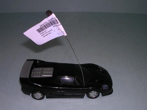
MQDMIL-538R
May 30, 2007Remote Control Car
Equipment Class
DXX - Part 15 Low Power Communication Device Transmitter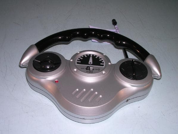
MQDMIL-538T
May 20, 2007Remote Control Car
Equipment Class
DXX - Part 15 Low Power Communication Device Transmitter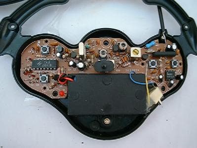
MQDMIL538T
Mar 02, 2004RC Toy Transmitter with 'Spy' Receiver
Equipment Class
DXT - Part 15 Low Power Transceiver, Rx Verified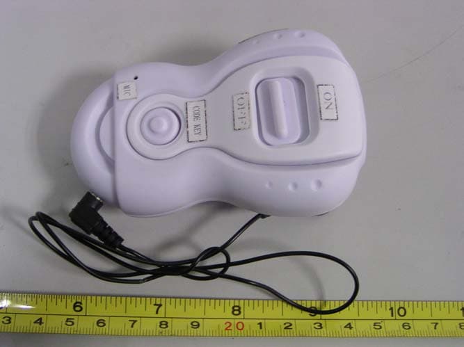
MQDMILWT-360
Feb 17, 2004Walkie- Talkie
Equipment Class
DXX - Part 15 Low Power Communication Device Transmitter