MRXFP4Tyre Pressure Monitor
Schrader Electronics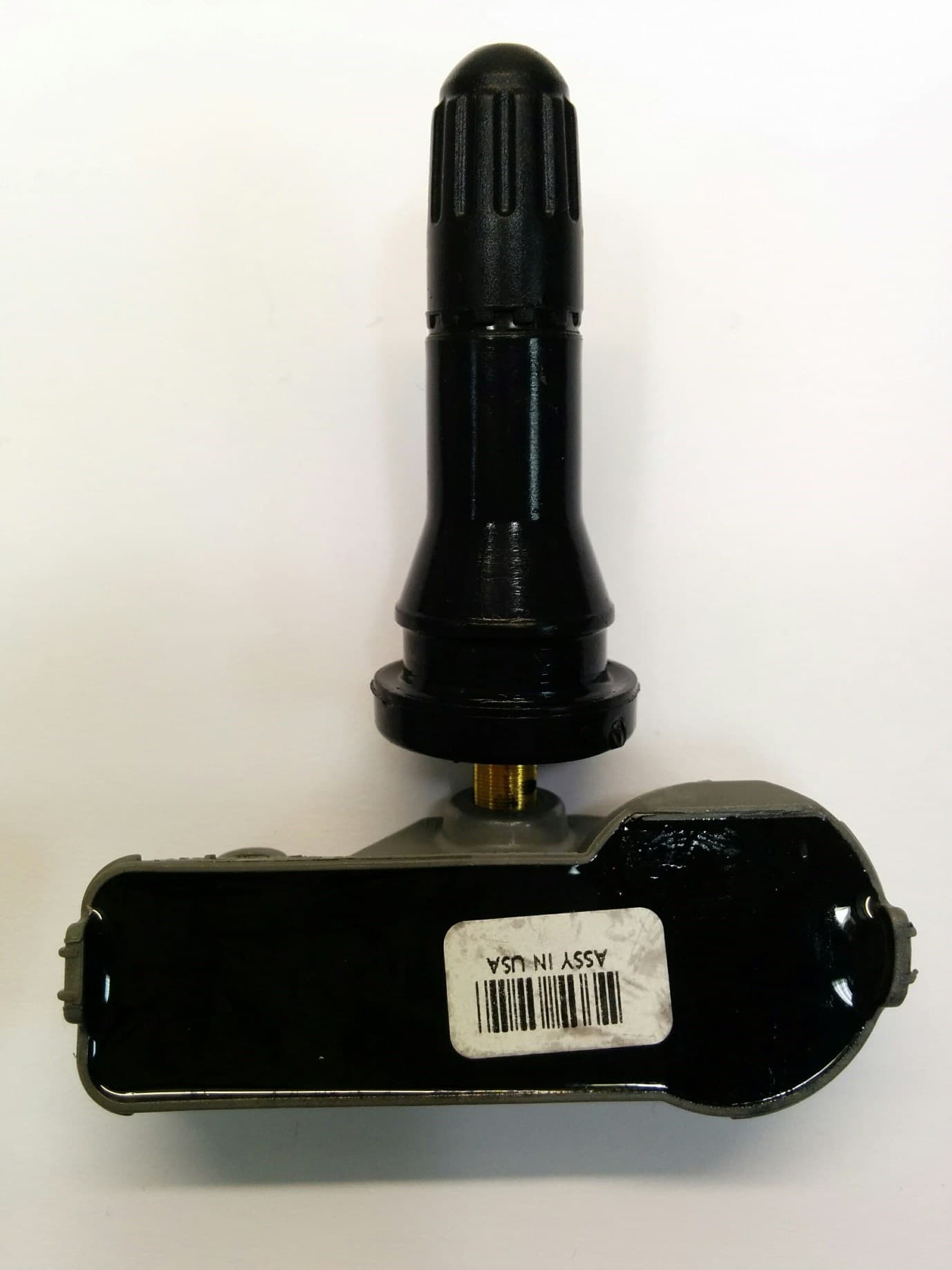
Click to zoom
Application Details
- Equipment Class
- DSC - Part 15 Security/Remote Control Transmitter
- Date of Grant
- Aug 30, 2022
- Application Purpose
- Original Equipment
- Date of Application
- Aug 30, 2022
- Equipment Note
- Tyre Pressure Monitor
- Frequency Range
- 433.92000000 - 433.92000000
- Company
- Schrader Electronics
- Country
- Ireland
Documents & Files
Document Text
Text extracted from the exhibit documents filed with the FCC. Open a document above to read the original.
Users Manual
http://www.tpmseuroshop.com/documents/declaration_conformities Schrader Electronics Ltd Unit 11 Technology Park Belfast Road Antrim, Northern Ireland, BT41 1QS TPMS (Tire Pressure Monitoring Sensor) Model PF4 User Manual Schrader Sensor Overview The Schrader Electronics TPMS (Tire Pressure Monitoring) Sensor is designed to be used in a direct measurement TPM System. The TPM Sensor is intended to interface to a receiver/decoder that has been designed to accept the TPM sensor protocol. The TPM Sensor is designed to monitor a vehicle's tyre pressure whilst driving or stationary. An electronic unit inside each tyre (referred to as the TPM Sensor or TPM transmitter) mounted to the valve stem, periodically measures actual tyre pressure/temperature. This pressure information is transmitted to a receiver/decoder by means of an RF link. The incoming radio frequency signals are decoded, and the data used to inform the driver of the tyre pressure information via the vehicles TPM interface. TPM Sensor main functions are: • Regularly measure the tyre pressure. • Monitor if the wheel is moving. • Periodically transmit tyre pressure using an RF link and a specific protocol. • Notify the system if there are abnormal pressure variations (leak) in the tyre. • Monitor the transponder input for valid LF field http://www.tpmseuroshop.com/documents/declaration_conformities Schrader Electronics Ltd Unit 11 Technology Park Belfast Road Antrim, Northern Ireland, BT41 1QS FCC ID: MRXFP4 IC: 2546A-FP4 This device complies with Part 15 of the FCC Rules Operation is subject to the following two conditions: (1) This device may not cause harmful interference, and (2) This device must accept any interference received, including interference that may cause undesired operation. WARNING: Changes or modifications not expressively approved by the party responsible for compliance could void the user's authority to operate the equipment. This device contains licence-exempt transmitter(s)/receiver(s) that comply with Innovation, Science and Economic Development Canada’s licence-exempt RSS(s). Operation is subject to the following two conditions: (1) This device may not cause interference. (2) This device must accept any interference, including interference that may cause undesired operation of the device. L’émetteur/récepteur exempt de licence contenu dans le présent appareil est conforme aux CNR d’Innovation, Sciences et Développement économique Canada applicables aux appareils radio exempts de licence. L’exploitation est autorisée aux deux conditions suivantes : 1) L’appareil ne doit pas produire de brouillage; 2) L’appareil doit accepter tout brouillage radioélectrique subi, même si le brouillage est susceptible d’en compromettre le fonctionnement. Radiation Exposure Statement: This equipment complies with FCC radiation exposure limits set forth for an uncontrolled environment. This equipment should be installed and operated with minimum distance 20cm between the radiator & your body Déclaration d’exposition aux radiations: Cet équipement est conforme aux limites d’exposition aux rayonnements ISED établies pour un environnement non contrôlé. Cet équipement doit être installé et utilisé à plus de 20cm entre le radiateur et votre corps. This equipment complies with ISED radiation exposure limits set forth for an uncontrolled environment. This equipment should be installed and operated with minimum distance 20cm between the radiator & your body
Cover Letter(s)
053019 – 12 Authority to Act as Agent Date: August 31, 2022 American Certification Body, Inc. 6731 Whittier Avenue Suite C110 McLean, VA 22101 To Whom It May Concern: _Compliance Engineering Ireland Ltd (Michael Kirby/John McAuley)_____ is authorized to act on our behalf, until otherwise notified, for applications to American Certification Body, Inc. (ACB). We certify that we are not subject to denial of federal benefits, that includes FCC benefits, pursuant to Section 5301 of the Anti-Drug Abuse Act of 1988, 21 U.S.C. 862. Further, no party, as defined in 47 CFR 1.2002 (b), to the application is subject to denial of federal benefits, that includes FCC benefits. We also declare that the information provided to the FCC is true and correct to the best of our knowledge (47 CFR 2.911(d)) and we have been informed of the grantee responsibilities (47 CFR 2.909) with regard to certified equipment. Thank you, Agency Agreement Expiration Date: __10 th Mar 2023 ___(Typically 8 – 12 months)_____ By: __________________________ _____________James Kyle___________ (Signature 1 ) (Print name) Title: _________RF Approval Co-ordinator_________________ On behalf of: ________Schrader Electronics Ltd__________________ (Company Name) Telephone: _________4402894483067_________________ 1 - Must be signed by applicant contact given for applicant on the FCC site, or by the authorized agent if an appropriate authorized agent letter has been provided. Letters should be placed on appropriate letterhead. 053019 – 12 Request for Confidentiality Date: August 31, 2022 Subject: Confidentiality Request for: ______(FCC ID: MRXFP4 IC ID:2546A-FP4)______ Pursuant to FCC 47 CFR 0.457(d) and 0.459 and IC RSP-100, Section 9.4, the applicant requests that a part of the subject FCC application be held confidential. Type of Confidentiality Requested Exhibit ☐ Short Term ☒ Permanent Block Diagrams ☐ Short Term External Photos ☐ Short Term ☒ Permanent * 2 Internal Photos ☐ Short Term ☒ Permanent Operation Description/Theory of Operation ☐ Short Term ☒ Permanent Parts List & Placement/BOM ☐ Short Term ☐ Permanent Tune-Up Procedure ☐ Short Term ☒ Permanent Schematics ☐ Short Term Test Setup Photos ☐ Short Term ☐ Permanent * 3 User’s Manual ______(Schrader Electronics Ltd )______ has spent substantial effort in developing this product and it is one of the first of its kind in industry. Having the subject information easily available to "competition" would negate the advantage they have achieved by developing this product. Not protecting the details of the design will result in financial hardship. EUT is potted. Permanent Confidentiality: The applicant requests the exhibits listed above as permanently confidential be permanently withheld from public review due to materials that contain trade secrets and proprietary information not customarily released to the public. Short-Term Confidentiality: The applicant requests the exhibits selected above as short term confidential be withheld from public view for a period of ___(specify number of days not to exceed 180) 3 ___ days from the date of the Grant of Equipment Authorization and prior to marketing. This is to avoid premature release of sensitive information prior to marketing or release of the product to the public. Applicant is also aware that they are responsible to notify ACB in the event information regarding the product or the product is made available to the public before the requested period has expired. ACB will then release the documents listed above for public disclosure pursuant to FCC Public Notice DA 04-1705. NOTE for Industry Canada Applications: IC currently only distinguishes Permanent Confidentiality exhibits as shown above. Short Term confidentiality is not considered applicable to IC applications. Sincerely, 2 - The asterisked items (*) require further information to be provided to ACB before permanent confidentiality will be extended to these exhibits. Please refer to FCC KDB 726920 and the specific Document link for D01 found at: https://apps.fcc.gov/oetcf/kdb/forms/FTSSearchResultPage.cfm?switch=P&id=41731 and review section II, 3) regarding specific information that must accompany these requests. 3 - Please refer to http://acbcert.com/documents/misc-docs/Memo-Short-Term-Vs-Standard-Confidentiality.pdf for complete details. 053019 – 12 By: __________________________ ______JAMES KYLE__________________ (Signature/Title 4 ) (Print name) 4 - Must be signed by applicant contact given for applicant on the FCC site, or by the authorized agent if an appropriate authorized agent letter has been provided. Letters should be placed on appropriate letterhead.
External Photos
EUT back also showing epoxy EUT front EUT side
ID Label/Location Info
Schrader Electronics Ltd Unit 11 Technology Park Belfast Road Antrim, Northern Ireland, BT41 1QS Part Marking Drawing Draft Model: FP4
RF Exposure Info
Compliance Engineering Ireland Ltd Clonross Lane, Derrockstown, Dunshaughlin Co. Meath, Ireland A85 XN59 Ph +353 1 8017000 , 8256722 www.cei.ie Project No. 22E910088-2a Quotation Q22-1508-1 Prepared For Schrader Electronics Ltd Address Unit 10 Antrim Technology Park Belfast Road Antrim Northern Ireland BT41 1QS Contact Zoe Gourley Contact (Phone) +44 2894 482536 Contact (Email) Gourley, Zoe [[email protected]] Prepared By Compliance Engineering Ireland Test Lab Address Clonross Lane, Derrockstown Dunshaughlin, Co. Meath Ireland, A85XN59 Test Report By Michael Kirby FCC Test Firm Registration 409640 ISED CAB identifier 8517A Date Received 21 st Aug 2022 Issue Date 26 th Aug 2022 EUT Description Sensor 433MHz, Tyre Pressure and Temperature Monitor FCC ID MRXFP4 IC ID 2546A-FP4 Authorised by Paul Reilly Authorised Signature: Report Ref: 22E9792-2a Page 2 of 3 RF Exposure Exhibit– Technical Report 1.0 Overview Fixed / Mobile Application MPE for bystanders which are considered to be ≥20cm away from the front of the transmit antenna 2. Maximum Permissible Exposure FCC 2.1 Limits /guidelines 47 CFR Sections 1.1307, 1.1310, 2.1091 447498 D01 General RF Exposure Guidance v06 EUT Rated power is 0.01mW 2.2 Results where: S = power density P = power input to the antenna G = power gain of the antenna in the direction of interest relative to an isotropic radiator R = distance to the center of radiation of the antenna Prediction frequency: 433.92 MHz Radiated Field Strength at 3m 75.2 dBuV/m Power Conversion factor for antenna distance 3m -95.2 dB EIRP Peak -20 dBm Time Averaging Factor 0 dB EIRP Peak -20 dBm EIRP Peak 0.01000 mW Prediction distance: 20 cm MPE limit for Uncontrolled/General Population exposure at prediction frequency: 0.29 mW/cm^2 Power density at prediction frequency: 0.00000199 mW/cm^2 Power density at prediction frequency: 0.000020 W/m^2 Test Result: Exempt from RF exposure test Pass Notes The table above shows that for a prediction distance of 20cm, RF exposure evaluation is not required. Report Ref: 22E9792-2a Page 3 of 3 2.0 Maximum Permissible Exposure IC Limits for Routine Evaluation — RF Exposure Evaluation 2.1 Limits /guidelines Limits for Routine Evaluation — RF Exposure Evaluation Limits as per RSS 102 Issue 5 (Mar 2015) 2.5.2 3.2 General population /Un-controlled Environments (IC) where: S = power density P = power input to the antenna G = power gain of the antenna in the direction of interest relative to an isotropic radiator R = distance to the center of radiation of the antenna Prediction frequency: 433.92 MHz EIRP Peak -20 dBm Time Averaging Factor 0.00 dB Tune up factor 0 dB EIRP Peak -20.0 dBm EIRP Peak 0.01 mW Prediction distance: 0 cm 2.5.2 Exemption limit for Routine Evaluation : 831.1 mW Exempt from Routine RF Exposure Evaluation The table above shows that RF exposure is exempt from routine RF exposure evaluation. End of Report
Test Report
Compliance Engineering Ireland Ltd Clonross Lane, Derrockstown, Dunshaughlin Co. Meath, Ireland A85 XN59 Ph +353 1 8017000 , 8256722 Confidential Report Project No. 22E10088-1 Quotation Q22-3006-1 Prepared For Sensata Schrader Electronics Ltd Address Unit 10 Antrim Technology Park Belfast Road Antrim Northern Ireland BT41 1QS Contact Zoe Gourley Contact (Phone) +44 2894 482536 Contact (Email) Gourley, Zoe [[email protected]] Prepared By Compliance Engineering Ireland Test Lab Address Clonross Lane Derrockstown Dunshaughlin Co. Meath Ireland A85XN59 Tested By Joy Israel Dalayap Test Report By Michael Kirby FCC Test Firm Registration 409640 ISED CAB identifier 8517A Date Received 22 nd Aug 2022 Issue Date 26 th Aug 2022 EUT Description Sensor 433MHz, Tyre Pressure Monitor FCC ID MRXFP4 IC ID 2546A-FP4 Authorised by Paul Reilly Authorised Signature: Report Ref: 22E10088-1 Page 2 of 26 TEST SUMMARY The equipment complies with the requirements according to the following standards. FCC Part Section(s) Industry Canada TEST PARAMETERS Test Result 15.231(e) 15.35 RSS-210 A1.4 RSS-Gen 6.10 Duty Cycle PASS 15.231(e) 15.209 RSS-210 A1.4 RSS-210 8.9 RADIATED EMISSIONS PASS 15.231(c) RSS-210 A1.3 20dB BANDWIDTH 99% Bandwidth PASS RSS 210 Issue 10 Dec 2019 (Amd Apr 2020) RSS-Gen Issue 5 Apr 2018 (Amd 1 Mar 2019) (Amd 2 Feb 2021) This report should not be reproduced, except in full, without the written approval of Compliance Engineering Ireland Ltd. Report Ref: 22E10088-1 Page 3 of 26 Exhibit A – Technical Report Table of Contents TEST SUMMARY .......................................................................................................................... 2 TABLE OF CONTENTS ................................................................................................................ 3 1 EUT DESCRIPTION .............................................................................................................. 4 2 EUT OPERATION ................................................................................................................. 5 2.1 Modifications ........................................................................................................ 5 2.2 Date of Test ......................................................................................................... 5 2.3 Electromagnetic Emissions Testing ..................................................................... 5 2.4 Special Test Software .......................................................................................... 5 3 EMISSIONS MEASUREMENTS ............................................................................................ 6 3.1 Conducted Emissions Measurements ................................................................. 6 3.2 Radiated Emissions Measurements .................................................................... 6 3.3 General ................................................................................................................ 6 3.3.1 Measurements in Transmit mode ................................................................. 6 3.3.2 Antenna Requirements ................................................................................. 7 3.3.3 Occupied Bandwidth and Duty Cycle ........................................................... 8 3.3.3.1 Occupied Bandwidth ................................................................................. 8 3.3.3.1.1 Results for Occupied Bandwidth 20dB Down ..................................... 8 3.3.3.1.2 Results for 99% Occupied Bandwidth ................................................ 9 3.3.4 Maximum Modulation Percentage (M %) / Duty cycle ................................ 10 4 FIELD STRENGTH OF RADIATED EMISSIONS ................................................................ 12 4.1 Test Specification: FCC 15.231(e) and RSS-210 A1.4 ...................................... 12 4.2 Results for Radiated Emissions ......................................................................... 13 4.2.1 Fundamental ............................................................................................... 13 4.2.2 Harmonics Spurious Emissions Measurements below 1GHz ..................... 14 4.2.3 Harmonics Spurious Emissions Measurements above 1GHz ..................... 15 4.2.4 Non-Harmonics Spurious Emissions Measurements .................................. 17 5 MEASUREMENT UNCERTAINTIES ................................................................................... 18 6 LIST OF TEST EQUIPMENT USED .................................................................................... 19 Appendix - A Scans for Spurious Emissions Test Configurations ................ 20 Appendix - B Test Configurations: ............................................................... 25 Appendix - C Block Diagrams of Test Setup ................................................ 26 Report Ref: 22E10088-1 Page 4 of 26 1 EUT Description The EUT was monitor using a short range 433.914 MHz band transmitter for reporting of tyre pressure and temperature in cars/trucks. Model: FP4 Type: Tyre Pressure Monitor Type of radio: Stand-alone Transmitter Type: ASK/FSK Operating Frequency Range(s): 433.92 MHz Number of Channels: One Antenna: Integral peak gain –18.9dBi Transmitter power configuration: 3 VDC Internal Battery. Operating. Temp Range: -40° C to +85° C Classification: DSC HVIN: FP4 FVIN: Ver 1.0 Test Methodology: Measurements performed according to the procedures in ANSI C63.10-2013 Table 1: Detailed Description of EUT Report Ref: 22E10088-1 Page 5 of 26 2 EUT Operation Operating Conditions during Test: The equipment under test was operated during the measurement under the following conditions: A sample (Sample #1) of EUT which was programmed to operate in test mode (CW mode) was used for all tests except duty cycle and bandwidth. A sample (Sample #2) of EUT which was programmed to operate in test mode (repeated modulated mode) was used for …
Text truncated - open the document above for the full version.
Test Report
Antenna Isotropic Peak Gain Pattern Ford SI Gen6 433.92MHz FP4 DOCUMENT NUMBER: LA12092016 ISSUE LEVEL: 01 Antenna Isotropic Peak Gain Pattern Ford SI Gen6 433.92MHz FP4 Page 1 of 8 UST serial communication Antenna Isotropic Peak Gain Pattern Ford SI Gen6 433.92MHz FP4.docx Page 1 of 8 CONFIDENTIAL Issue Amendment History Name of Author Date 01 First Issue Lahbib Assila 12-09-2016 Document #: LA12092016 Destination: Reference: Issue: 01 Date: 12/09/2016 ECN #: Author: Lahbib Assila Approver: Emmanuel Marguet Contributors: Antenna Isotropic Peak Gain Pattern Ford SI Gen6 433.92MHz FP4 Antenna Isotropic Peak Gain Pattern Ford SI Gen6 433.92MHz FP4 DOCUMENT NUMBER: LA12092016 ISSUE LEVEL: 01 Antenna Isotropic Peak Gain Pattern Ford SI Gen6 433.92MHz FP4 Page 2 of 8 UST serial communication Antenna Isotropic Peak Gain Pattern Ford SI Gen6 433.92MHz FP4.docx Page 2 of 8 CONFIDENTIAL Table of Contents Table of Contents ..................................................................................................................................................... 2 i. ABBREVIATIONS / GLOSSARY .................................................................................................................... 3 ii. SUPPORTING DOCUMENTS ...................................................................................................................... 3 iii. DOCUMENT HISTORY AND STORAGE ....................................................................................................... 3 1. Introduction ...................................................................................................................................................... 4 2. Antenna gain. .................................................................................................................................................... 5 Antenna Isotropic Peak Gain Pattern Ford SI Gen6 433.92MHz FP4 DOCUMENT NUMBER: LA12092016 ISSUE LEVEL: 01 Antenna Isotropic Peak Gain Pattern Ford SI Gen6 433.92MHz FP4 Page 3 of 8 UST serial communication Antenna Isotropic Peak Gain Pattern Ford SI Gen6 433.92MHz FP4.docx Page 3 of 8 CONFIDENTIAL i. ABBREVIATIONS / GLOSSARY TERM EXPANSION/MEANING dBi Decibel Isotropic ii. SUPPORTING DOCUMENTS REFERENCE ISSUE iii. DOCUMENT HISTORY AND STORAGE DOCUMENT NAME LOCATION Antenna Isotropic Peak Gain Pattern Ford SI Gen6 433.92MHz FP4 DOCUMENT NUMBER: LA12092016 ISSUE LEVEL: 01 Antenna Isotropic Peak Gain Pattern Ford SI Gen6 433.92MHz FP4 Page 4 of 8 UST serial communication Antenna Isotropic Peak Gain Pattern Ford SI Gen6 433.92MHz FP4.docx Page 4 of 8 CONFIDENTIAL 1. Introduction This document shows the antenna pattern and antenna gain of Ford SI Gen6 433.92MHz FP4 transmitters. Description of transmitter positioning: All measurements are done in Anechoic Chamber at 3m with TX on table in 3 positions as follow: Pos. 0 Pos. 1 Pos. 2 Antenna Isotropic Peak Gain Pattern Ford SI Gen6 433.92MHz FP4 DOCUMENT NUMBER: LA12092016 ISSUE LEVEL: 01 Antenna Isotropic Peak Gain Pattern Ford SI Gen6 433.92MHz FP4 Page 5 of 8 UST serial communication Antenna Isotropic Peak Gain Pattern Ford SI Gen6 433.92MHz FP4.docx Page 5 of 8 CONFIDENTIAL 2. Antenna gain. Test equipment used: Category Mark Type Anechoic Test Site Schrader Electronics Spectrum analyzer Agilent E4404B Coaxial cable RG214U 50 Ohm 11m Open Boundary Quad-Ridged Horns antenna ETS Lindgren 3164-06 Conditions: The test is performed in anechoic test site. The Transmitter is placed on a turntable. Antenna Isotropic Peak Gain Pattern Ford SI Gen6 433.92MHz FP4 DOCUMENT NUMBER: LA12092016 ISSUE LEVEL: 01 Antenna Isotropic Peak Gain Pattern Ford SI Gen6 433.92MHz FP4 Page 6 of 8 UST serial communication Antenna Isotropic Peak Gain Pattern Ford SI Gen6 433.92MHz FP4.docx Page 6 of 8 CONFIDENTIAL -65 -60 -55 -50 -45 -40 -35 -30 -25 -20 -15 -180 -175 -170 -165 -160 -155 -150 -145 -140 -135 -130 -125 -120 -115 -110 -105 -100 -95 -90 -85 -80 -75 -70 -65 -60 -55 -50 -45 -40 -35 -30 -25 -20 -15 -10 -5 0 5 10 15 20 25 30 35 40 45 50 55 60 65 70 75 80 85 90 95 100 105 110 115 120 125 130 135 140 145 150 155 160 165 170 175 Gain in dBi Position 0 polarisations V , H and Module POS_0_H POS_0_V POS_0_M Antenna Isotropic Peak Gain Pattern Ford SI Gen6 433.92MHz FP4 DOCUMENT NUMBER: LA12092016 ISSUE LEVEL: 01 Antenna Isotropic Peak Gain Pattern Ford SI Gen6 433.92MHz FP4 Page 7 of 8 UST serial communication Antenna Isotropic Peak Gain Pattern Ford SI Gen6 433.92MHz FP4.docx Page 7 of 8 CONFIDENTIAL -65 -60 -55 -50 -45 -40 -35 -30 -25 -20 -15 -180 -175 -170 -165 -160 -155 -150 -145 -140 -135 -130 -125 -120 -115 -110 -105 -100 -95 -90 -85 -80 -75 -70 -65 -60 -55 -50 -45 -40 -35 -30 -25 -20 -15 -10 -5 0 5 10 15 20 25 30 35 40 45 50 55 60 65 70 75 80 85 90 95 100 105 110 115 120 125 130 135 140 145 150 155 160 165 170 175 Gain in dBi Position1 polarisations V , H and Module POS_1_H POS_1_V POS_1_M Antenna Isotropic Peak Gain Pattern Ford SI Gen6 433.92MHz FP4 DOCUMENT NUMBER: LA12092016 ISSUE LEVEL: 01 Antenna Isotropic Peak Gain Pattern Ford SI Gen6 433.92MHz FP4 Page 8 of 8 UST serial communication Antenna Isotropic Peak Gain Pattern Ford SI Gen6 433.92MHz FP4.docx Page 8 of 8 CONFIDENTIAL Peak antenna gain: -18.9dBi -65 -60 -55 -50 -45 -40 -35 -30 -25 -20 -15 -180 -175 -170 -165 -160 -155 -150 -145 -140 -135 -130 -125 -120 -115 -110 -105 -100 -95 -90 -85 -80 -75 -70 -65 -60 -55 -50 -45 -40 -35 -30 -25 -20 -15 -10 -5 0 5 10 15 20 25 30 35 40 45 50 55 60 65 70 75 80 85 90 95 100 105 110 115 120 125 130 135 140 145 150 155 160 165 170 175 Gain in dBi Position2 polarisations V , H and Module POS_2_H POS_2_V POS_2_M
Test Setup Photos
Test Set up Fig 1a Test setup 30MHz -300MHz Rad Emissions Fig 1b Test setup 30MHz -300MHz Rad Emissions Fig 2a Test setup 300MHz -1GHz Rad Emissions Fig 2b Test setup 300MHz -1GHz Rad Emissions Fig 3 Test setup 1GHz 6GHz Rad Emissions Fig 4a EUT close up Rad Emissions Fig 4b EUT close up Rad Emissions Fig 5a EUT Fig 5b EUT End of Report
Contact Information
Applicant
James Kyle
Technical Contact
Schrader Electronics LtdJames Kyle
[email protected]028 9448
Unit 11 Technology Park · Antrim N · Ireland
Test Firm
Compliance Engineering Ireland Ltd. (CEI)John McAuley
Technical Specifications
| # | Rule Parts | Frequency Range | Power Output |
|---|---|---|---|
| 1 | 15.231,15.231(e) | 433.92 MHz - 433.92 MHz | 10.00 mW |
Other Applications from Schrader Electronics
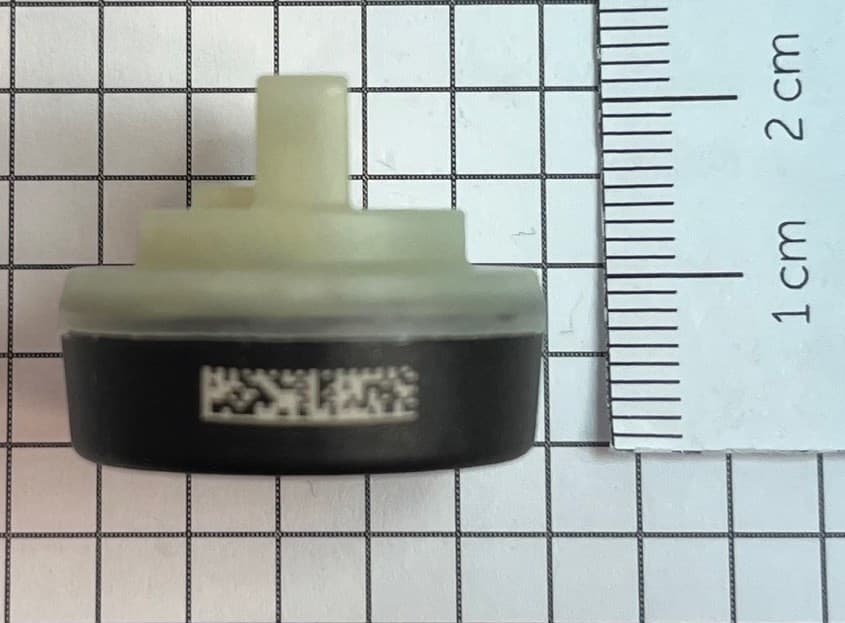
MRXFTMS01
Apr 17, 2024Tyre Pressure Monitor
Equipment Class
DSC - Part 15 Security/Remote Control Transmitter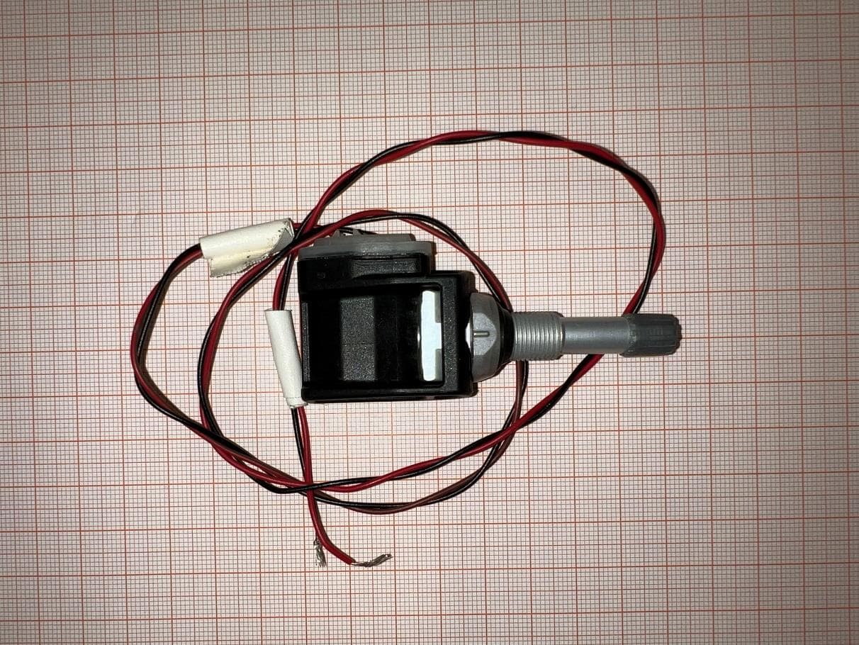
MRXBG6FD4
Jun 27, 2023Tyre Pressure Monitoring Sensor
Equipment Class
DSC - Part 15 Security/Remote Control Transmitter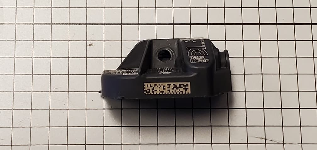
MRXBBFPL4
Mar 26, 2023TPMS Sensor
Equipment Class
DSC - Part 15 Security/Remote Control Transmitter
MRXSCHEB
Jan 25, 2023Tyre Pressure Monitoring System
Equipment Class
DTS - Digital Transmission System
MRXAG2FSC4
Apr 10, 2022TPM Transmitter
Equipment Class
DSC - Part 15 Security/Remote Control Transmitter