MRXSCHEBTyre Pressure Monitoring System
Schrader Electronics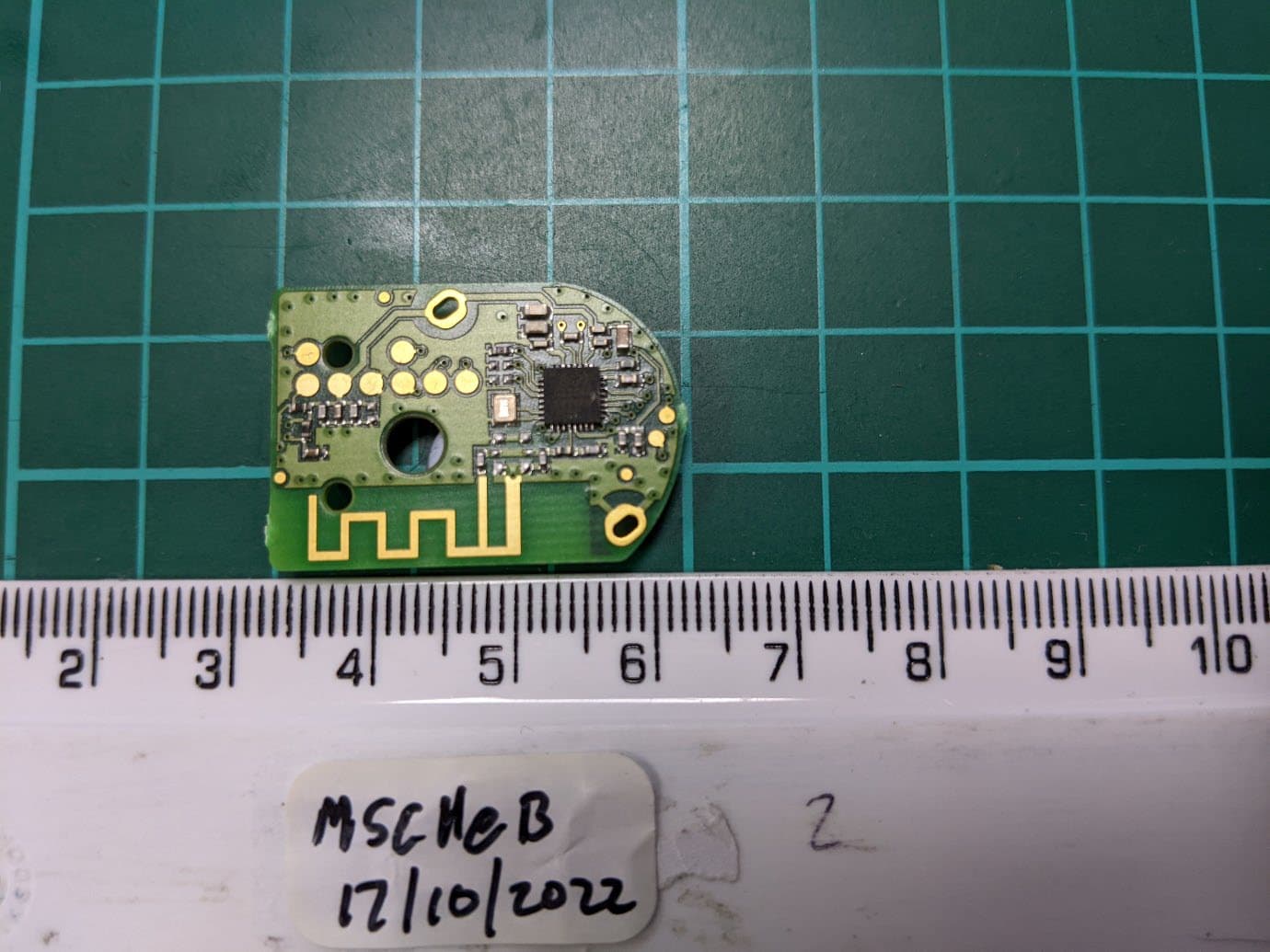
Click to zoom
Application Details
- Equipment Class
- DTS - Digital Transmission System
- Date of Grant
- Jan 25, 2023
- Application Purpose
- Original Equipment
- Date of Application
- Jan 24, 2023
- Equipment Note
- Tyre Pressure Monitoring System
- Frequency Range
- 2402.00000000 - 2480.00000000
- Company
- Schrader Electronics
- Country
- Ireland
Documents & Files
Document Text
Text extracted from the exhibit documents filed with the FCC. Open a document above to read the original.
Users Manual
The device under test is manufactured by the grantee (Schrader Electronics) and sold as an OEM product. Per 47 CFR 2.909, 2.927, 2.931, 2.1033, 15.15(b) etc..., the grantee must ensure the end-user has all applicable / appropriate operating instructions. When end-user instructions are required, as in the case of this product, the grantee must notify the OEM to notify the end- user. Schrader Electronics will supply this document to the reseller/distributor dictating what must be included in the end user’s manual for the commercial product. INFORMATION TO BE INCLUDED IN THE END USER'S MANUAL The following information ( in blue) must be included in the end product user’s manual to ensure continued FCC and Industry Canada regulatory compliance. The ID numbers must be included in the manual if the device label is not readily accessible to the end user. The compliance paragraphs below must be included in the user's manual. ****************************************************************************** FCC ID:MRXSCHEB IC: 2546A- S CHEB This device complies with Part 15 of the FCC Rules and with Licence exempt RSS standards of Industry Canada. Operation is subject to the following two conditions: (1) This device may not cause harmful interference, and (2) This device must accept any interference received, including interference that may cause undesired operation. Le présent appareil est conforme aux CNR d'Industrie Canada applicables aux appareils radio exempts de licence. L'exploitation est autorisée aux deux conditions suivantes: (1) l'appareil ne doit pas produire de brouillage, et (2) l'utilisateur de l'appareil doit accepter tout brouillage radioélectrique subi, même si le brouillage est susceptible d'en compromettre le fonctionnement. WARNING: Changes or modifications not expressively approved by the party responsible for compliance could void the user's authority to operate the equipment. The term “IC:” before the radio certification number only signifies that Industry Canada technical specifications were met. ******************************************************************************
Users Manual
SCHRADER ELECTRONICS.LTD.. MODEL :SCHEB USER MANUAL The TPMS Transmitter is installed to the valve body in each tyre of a vehicle. The unit measures tyre pressure periodically and transmits this information by RF communication to a r eceiver inside the vehicle. In addition, the TPMS Transmitter performs the following functions: • Determines a temperature compensated pressure value. • Determines any abnormal pressure variations in the wheel. • Monitors the state of the Transmitters’ internal battery and informs the receiver of a low battery condition. Fig 1: Sensor block diagram Fig 2: Schematic diagram (Please see SCHEB Circuit Schematic File.) Modes Rotating Mode While the sensor/transmitter in the Rotating Mode, it shall satisfy the following requirements. The sensor/transmitter shall transmit an instantaneous measured data, if a pressure change of 2.0 psi from the last transmission or greater has occurred with respect to the following conditions. If the pressure change was a decrease of pressure, the sensor/transmitter shall transmit immediately every time it detects the 2.0-psi or greater pressure changes from the last transmission. If the pressure change of 2.0 psi or greater was an increase of pressure, the sensor shall not react to it. Stationary Mode While the sensor/transmitter in the Stationary Mode, it shall satisfy the following requirements. The sensor/transmitter shall transmit an instantaneous measured data, if a pressure change of 2.0 psi from the last transmission or greater has occurred with respect to the following conditions. If the pressure change was a decrease of pressure, the sensor/transmitter shall transmit immediately every time it detects the 2.0-psi or greater pressure changes from the last transmission. If the pressure change of 2.0 psi or greater was an increase of pressure, the silent period between the RPC transmission and the last transmission shall be 30.0 seconds, and the silent period between the RPC transmission and the next transmission (Normal scheduled transmission or another RPC transmission) shall also be 30.0 seconds, to be in compliance of FCC Part 15.231. Factory Mode The factory mode is the mode that the sensor shall transmit more often in the factory to assure the programmability of the sensor ID during the manufacturing process. Off Mode This Off Mode is only for production parts sensors that are used for the builds during the production process and not in the service environment. LF Initiation The sensor/transmitter must provide data upon the presence of an LF signal. The sensor must react (Transmit and provide data) no later than 150.0 ms after the LF data code has been detected at the sensor. The sensor/transmitter must be sensitive (As sensitivity is defined in Table 1) and able to detect the LF field.
Cover Letter(s)
CSF047 1.1 LETTER OF AGENCY Date:17.10.2022 Element Materials Technology 100 Frobisher Business Park Malvern Worcestershire WR14 1BX UK To Whom It May Concern: We certify that we are not subject to denial of federal benefits, that includes FCC benefits, pursuant to Section 5301 of the Anti-Drug Abuse ACT of 1988, U.S.C. 862. Further, no party, as defined in 47 CFR 1.2002(b), to the application, is subject to denial of federal benefits, that includes FCC benefits. Thank you for your attention to this matter. Yours faithfully Company.Sensata Technologies Ltd Signature. Full Name.James Kyle
Cover Letter(s)
CSF047 1.1 LETTER OF AGENCY Date:17.10.2022 Element Materials Technology 100 Frobisher Business Park Malvern Worcestershire WR14 1BX UK To Whom It May Concern: We certify that we are not subject to denial of federal benefits, that includes FCC benefits, pursuant to Section 5301 of the Anti-Drug Abuse ACT of 1988, U.S.C. 862. Further, no party, as defined in 47 CFR 1.2002(b), to the application, is subject to denial of federal benefits, that includes FCC benefits. Thank you for your attention to this matter. Yours faithfully Company.Sensata Technologies Ltd Signature. Full Name.James Kyle
ID Label/Location Info
F E D C B A 8 7 654321 A B C D E F 1 ENG-F-044 ISS 05 2345678 SUPPLIERS - PLEASE NOTE WHEN IN COMMUNICATION WITH SENSATA ABOUT DRAFT ITEMS, PLEASE USE PART NUMBER TOGETHER WITH 3D CAD VERSION AS UNIQUE IDENTIFIER OF REFERENCED 3D CAD MODEL 3D CAD VERSION PART NO. DRAFT - FOR TECHNICAL FEEDBACK OR QUOTATION PURPOSES ONLY DRAWING VERSION 14 70403115205 24 04 09 03 05 07 10 11 FCC ID:MRXSCHEB ICC:2546A-SCHeB M:SCHeB 9816 XXXXXXXXXXXX MADE IN UK YYMMDD 02 13 03 01 06 12 08 03 03 03 TABLE 4 MECH CODE 01827 TABLE 3 PRODUCTION LOCATIONCOUNTRY OF MANUFACTURE ANTRIMMADE IN UK TABLE 2 PRODUCT MARKINGS LABEL No. DESCRIPTION TEXT/ LOGO [TEXT FONT: DIN1451] SIZE REQUIRED 01CUSTOMER PART No.98160.9mm 02COUNTRY OF MANUFACTUREMADE IN UK0.9mm 03PRODUCTION DATEYYMMDD0.9mm 04HOMOLOGATION MODEL NAMEM:SCHeB0.9mm 05QR CODE QR CODE (ENCODED WITH MAC ADDRESS) 5.0mm x 5.0mm 06BLUETOOTH SYMBOL3mm 07BIN SYMBOL5mm 08 VALVE BODY ID 2D DATA MATRIX (CONTAINING MECHANICAL ID 01827) 2D MATRIX10.0mm x 2.5mm 09MAC ADDRESSXXXXXXXXXXXX0.9mm TABLE 1 COUNTRY APPROVALS LABEL No. REGIONAUTHORITYSYMBOL REF. CODE/ TEXT [TEXT FONT: DIN1451] REQ. ON SENSOR SIZE REQUIRED SYMBOLTEXT 10UKUKCAN/ASYMBOL3.0mmN/A 11EUROPEREDN/ASYMBOL3.0mmN/A 12USAFCCN/AFCC ID:MRXSCHEBTEXTN/A0.9mm 13CANADAICN/AIC: 2546A-SCHeBTEXTN/A0.9mm 03A3 SCHRADER EBIKE BLE 2.4GHZ 70403115205 - LASER MARKING DRAWING - DRAFT 00017157 PRJ0012190 N/A N/A SEE NOTES FOR GENERAL TOLERANCE INTERPRET DRAWING PER ASME Y14.5-2009 THIRD ANGLE PROJECTION DO NOT SCALE DRAWING UNLESS OTHERWISE SPECIFIED DIMENSIONS ARE IN MILLIMETERS REVISION SYMBOL PROJECT NO. MASS (g) MATERIAL FOR REFERENCE ONLY, CHECK LATEST REVISION BEFORE USE. REFER TO PLM FOR CONTROLLED DATA, CHANGE HISTORY AND APPROVALS. TECHNOLOGY PARK, ANTRIM, UK, BT41 1QS SHEET 1 OF 1SOLIDWORKS 2020SCALE 2:1 DRAWING REV.DRAWING NO.SIZE TITLE PART NUMBER 70403115205 THIS DRAWING IS CONFIDENTIAL AND PROPRIETARY OF SCHRADER ELECTRONICS LIMITED. THE INFORMATION CONTAINED WITHIN IT MAY NOT BE USED, DISCLOSED OR REPRODUCED IN WHOLE OR PART, WITHOUT THE EXPRESSED WRITTEN CONSENT OF SCHRADER ELECTRONICS LIMITED. NO RIGHT IS GRANTED TO DISCLOSE OR USE ANY INFORMATION CONTAINED WITHIN THIS DRAWING. SCHRADER ELECTRONICS LIMITED IS PART OF THE SENSATA TECHNOLOGIES GROUP. 15/DEC/2021ECO-470991R.RINITIAL RELEASE01 DATEECOBYREVISION DESCRIPTIONREV 13/OCT/2022 26/JAN/2022 DFCO09977 ECO-477637 R.F R.R FCC AND IC APPROVALS ADED TO DRAWING VIEW AND TABLE 1 03 02 HOMOLOGATION MODEL NAME ADDED. MAC ADDRESS ADDED
Operational Description
Sensata Technologies Inc. Strictly Confidential. © Copyright Sensata Technologies Inc. 2015. All rights reserved. Hard copy is uncontrolled. The World Depends on Sensors and Controls Issue Amendment History Name of Author Date 01 Initial release Nicolas Henriet 02-12-21 Author: (Name) Author: (Signature) Approver: (Name) Approver: (Signature) Date: Thomas Guillemin RF Design & Development Support Engineer Emmanuel Marguet RF Design & Development Support Team Manager Document #: NH021221-1 Destination: Reference: Issue: 01 Date: 02/12/2021 ECN #: Author: Nicolas Henriet Approver: Emmanuel Marguet Contributors: Antenna Isotropic Peak Gain Pattern Ebike sensor Antenna Isotropic Peak Gain Pattern Ebike sensor DOCUMENT NUMBER: NH021221-1 ISSUE LEVEL: 01 Antenna Isotropic Peak Gain Pattern Ebike BLE.docx Page 2 of 9 Table of Contents Table of Contents ......................................................................................................................................... 2 i. ABBREVIATIONS / GLOSSARY .................................................................................................................... 3 ii. SUPPORTING DOCUMENTS ...................................................................................................................... 3 iii. DOCUMENT HISTORY AND STORAGE ....................................................................................................... 3 1. Introduction ......................................................................................................................................... 4 2. Antenna gain ........................................................................................................................................ 5 Antenna Isotropic Peak Gain Pattern Ebike sensor DOCUMENT NUMBER: NH021221-1 ISSUE LEVEL: 01 Antenna Isotropic Peak Gain Pattern Ebike BLE.docx Page 3 of 9 i. ABBREVIATIONS / GLOSSARY TERM EXPANSION/MEANING dBi Decibel Isotropic ii. SUPPORTING DOCUMENTS REFERENCE ISSUE iii. DOCUMENT HISTORY AND STORAGE DOCUMENT NAME LOCATION Antenna Isotropic Peak Gain Pattern Ebike sensor DOCUMENT NUMBER: NH021221-1 ISSUE LEVEL: 01 Antenna Isotropic Peak Gain Pattern Ebike BLE.docx Page 4 of 9 1. Introduction This document shows the antenna pattern and antenna gain of Ebike BLE transmitters. Description of transmitter positioning: All measurements are done in Anechoic Chamber at 3m with TX on table in 3 positions as follow: Pos. 1 Pos. 2 Pos. 3 Test Antenna at 3m Test Antenna at 3m Test Antenna at 3m Turn table Turn table Turn table Antenna Isotropic Peak Gain Pattern Ebike sensor DOCUMENT NUMBER: NH021221-1 ISSUE LEVEL: 01 Antenna Isotropic Peak Gain Pattern Ebike BLE.docx Page 5 of 9 2. Antenna gain Test equipment used: Category Mark Type Anechoic Test Site Sensata Spectrum analyser Agilent E4404B Coaxial cable RG214U 50 Ohm 11m Open Boundary Quad-Ridged Horns antenna ETS Lindgren 3164-06 Conditions: The test is performed in anechoic test site. The Transmitter is placed on a turntable in continuous transmitted emission. Antenna Isotropic Peak Gain Pattern Ebike sensor DOCUMENT NUMBER: NH021221-1 ISSUE LEVEL: 01 Antenna Isotropic Peak Gain Pattern Ebike BLE.docx Page 6 of 9 Gain in dBi Position1 polarisations V, H and Module Ebike sensor 2402MHz 2426MHz 2480MHz Antenna Isotropic Peak Gain Pattern Ebike sensor DOCUMENT NUMBER: NH021221-1 ISSUE LEVEL: 01 Antenna Isotropic Peak Gain Pattern Ebike BLE.docx Page 7 of 9 Gain in dBi Position2 polarisations V, H and Module Ebike sensor 2402MHz 2426MHz 2480MHz Antenna Isotropic Peak Gain Pattern Ebike sensor DOCUMENT NUMBER: NH021221-1 ISSUE LEVEL: 01 Antenna Isotropic Peak Gain Pattern Ebike BLE.docx Page 8 of 9 Gain in dBi Position3 polarisations V, H and Module Ebike sensor 2402MHz 2426MHz 2480MHz Sensata Technologies Inc. Strictly Confidential. © Copyright Sensata Technologies Inc. 2015. All rights reserved. Hard copy is uncontrolled. The World Depends on Sensors and Controls Peak antenna gain: 1.7dBi
Test Report
RF990b 1.0 General SAR test reduction & exclusion guidance KDB 447498 Section 4.3 General SAR test reduction and exclusion guidance For Standalone SAR exclusion consideration, when SAR Exclusion Threshold requirement in KDB 447498 is satisfied, standalone SAR evaluation for general population exposure conditions by measurement or numerical simulation is not required. The SAR Test Exclusion Threshold for frequencies in the range 100 MHz to 6 GHz, and for test separation distance of ≤ 50 mm, is determined as follows. SAR Exclusion Threshold (SARET) = (NT x TSD A ) / √ f GHz Where, NT = Numeric Threshold (3.0 for 1-g SAR and 7.5 for 10-g SAR) TSDA = Minimum Test separation distance or 50 mm (whichever is lower) fGHz = Transmit frequency in GHz Channel Frequency (MHz) Maximum Conducted Power (mW) SAR Exclusion Threshold at 5 mm (mW) SAR Evaluation 2402 0.125 9.7 Not Required 2440 0.087 9.6 Not Required 2480 0.125 9.5 Not Required Therefore standalone SAR evaluation for general population exposure conditions by measurement or numerical simulation is not required.
Test Report
Report on the Radio Testing For Schrader Electronics Ltd on Schrader BLE TPMS Report no. TRA-056478-45-02A 20th January 2023 REPORT ON THE RADIO TESTING OF A Schrader Electronics Ltd Schrader BLE TPMS WITH RESPECT TO SPECIFICATION FCC 47CFR 15.247 TEST DATE: 2022-10-10 to 2022-10-12 Tested by: D Garvey Written by: D Garvey Radio Test Engineer Approved by: D Winstanley Radio Senior Test Engineer Date: 20th January 2023 Disclaimers: [1] THIS DOCUMENT MAY BE REPRODUCED ONLY IN ITS ENTIRETY AND WITHOUT CHANGE [2] THE RESULTS CONTAINED IN THIS DOCUMENT RELATE ONLY TO THE ITEM(S) TESTED Report Number: TRA-056478-45-02A Issue: A Report Number: TRA-056478-45-02A Page 3 of 45 1 Revision Record Issue Number Issue Date Revision History A 20th January 2023 Original Report Number: TRA-056478-45-02A Page 4 of 45 2 Summary TEST REPORT NUMBER: TRA-056478-45-02A WORKS ORDER NUMBER: TRA-056478-05 PURPOSE OF TEST: Certification TEST SPECIFICATION: 47CFR15.247 EQUIPMENT UNDER TEST (EUT): Schrader BLE TPMS FCC IDENTIFIER: MRXSCHEB EUT SERIAL NUMBER: Not Stated MANUFACTURER/AGENT: Schrader Electronics Ltd ADDRESS: 11 Technology Park Belfast Road Antrim Co. Antrim BT41 1QS Ireland CLIENT CONTACT: Zoe Gourley 02894 482 536 [email protected] ORDER NUMBER: 6808900051451 TEST DATE: 2022-10-10 to 2022-10-12 TESTED BY: D Garvey Element Report Number: TRA-056478-45-02A Page 5 of 45 2.1 Test Summary Test Method and Description Requirement Clause 47CFR15 Applicable to this equipment Result / Note Radiated spurious emissions (restricted bands of operation and cabinet radiation) 15.247 (d) Pass AC power line conducted emissions 15.207 Note 1 Occupied bandwidth 15.247 (a) (2) Pass Conducted carrier power Peak 15.247 (b) (3) Pass Max. Out of band emissions 15.247 (d) Pass Power spectral density 15.247 (e) Pass Calculation of duty correction - Note 2 Specific Note: 1. The EUT is a battery powered device. 2. No duty cycle correction was required General Notes: The results contained in this report relate only to the items tested, in the condition at time of test, and were obtained in the period between the date of initial receipt of samples and the date of issue of the report. The apparatus was set up and exercised using the configurations, modes of operation and arrangements defined in this report only. Any modifications made are identified in Section 8 of this report. Particular operating modes, apparatus monitoring methods and performance criteria required by the standards tested to have been performed except where identified in Section 5.2 of this test report (Deviations from Test Standards). Report Number: TRA-056478-45-02A Page 6 of 45 3 Contents 1 Revision Record ............................................................................................................................................ 3 2 Summary ....................................................................................................................................................... 4 2.1 Test Summary ....................................................................................................................................... 5 3 Contents ........................................................................................................................................................ 6 4 Introduction ................................................................................................................................................... 7 5 Test Specifications ........................................................................................................................................ 8 5.1 Normative References ........................................................................................................................... 8 5.2 Deviations from Test Standards ............................................................................................................ 8 6 Glossary of Terms ......................................................................................................................................... 9 7 Equipment under Test ................................................................................................................................. 10 7.1 EUT Identification ................................................................................................................................ 10 7.2 System Equipment .............................................................................................................................. 10 7.3 EUT Mode of Operation ...................................................................................................................... 10 7.4 EUT Radio Parameters ....................................................................................................................... 10 7.4.1 General ....................................................................................................................................... 10 7.5 EUT Description .................................................................................................................................. 10 8 Modifications ............................................................................................................................................... 11 9 EUT Test Setup ........................................................................................................................................... 12 9.1 Block Diagram ..................................................................................................................................... 12 9.2 General Set-up Photograph ................................................................................................................ 13 9.3 Measurement software ........................................................................................................................ 14 10 General Technical Parameters ................................…
Text truncated - open the document above for the full version.
Contact Information
Applicant
James Kyle
Test Firm
Element Materials Technology Warwick LtdNeil Roche
Technical Specifications
| # | Rule Parts | Frequency Range | Power Output |
|---|---|---|---|
| 1 | 15C | 2.40 GHz - 2.48 GHz | 125.00 µW |
Other Applications from Schrader Electronics
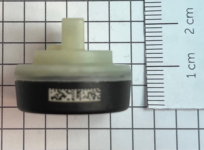
MRXFTMS01
Apr 17, 2024Tyre Pressure Monitor
Equipment Class
DSC - Part 15 Security/Remote Control Transmitter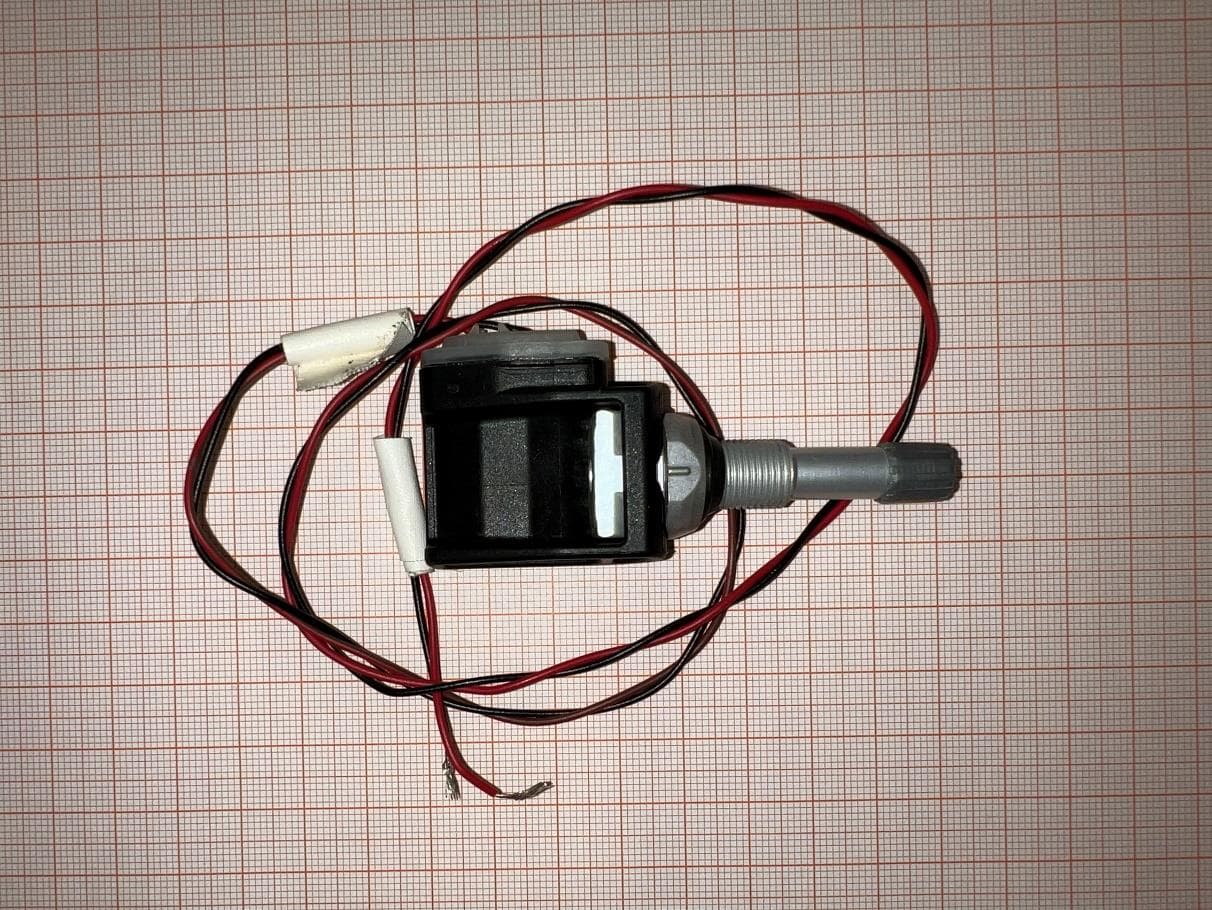
MRXBG6FD4
Jun 27, 2023Tyre Pressure Monitoring Sensor
Equipment Class
DSC - Part 15 Security/Remote Control Transmitter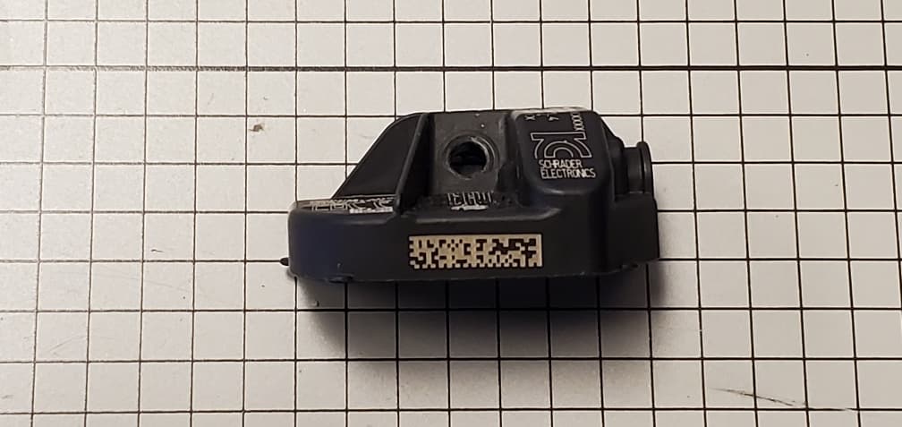
MRXBBFPL4
Mar 26, 2023TPMS Sensor
Equipment Class
DSC - Part 15 Security/Remote Control Transmitter
MRXFP4
Aug 30, 2022Tyre Pressure Monitor
Equipment Class
DSC - Part 15 Security/Remote Control Transmitter
MRXAG2FSC4
Apr 10, 2022TPM Transmitter
Equipment Class
DSC - Part 15 Security/Remote Control Transmitter