MS3S2G0508FM Modulator
Ever Win International Corporation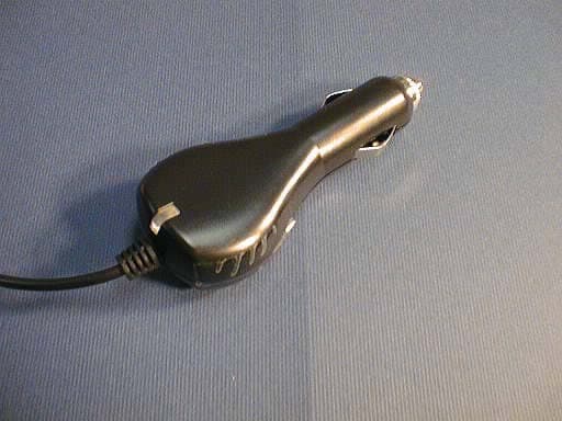
Click to zoom
Application Details
- Equipment Class
- DXX - Part 15 Low Power Communication Device Transmitter
- Date of Grant
- Oct 30, 2005
- Application Purpose
- Original Equipment
- Date of Application
- Oct 30, 2005
- Equipment Note
- FM Modulator
- Frequency Range
- 88.10000000 - 89.50000000
- Country
- United States
Documents & Files
Document Text
Text extracted from the exhibit documents filed with the FCC. Open a document above to read the original.
Users Manual
EverWin International Wireless MP3 player User guide Setup Instructions: The EverWin International model # S2G0508 Wireless MP3 adapter is your own personal FM broadcast station intended for use exclusively inside an automobile with a 12v cigarette lighter outlet. 1. Plug the Wireless MP3 adapter to your MP3 player equipped cell-phone. 2. Plug the Wireless MP3 adapter to your automobile 12v cigarette lighter outlet. 3. Set the Wireless MP3 adapter to desired FM channel by pressing the push button switch and noting the channel indication on the adapter. 4. Tune your auto FM stereo to same channel as indicated by wireless MP3 adapter 5. Select an album on the MP3 player of your cell-phone and push the playback button. 6. Adjust FM stereo volume control to desired level. For best results, preset the MP3 adapter to FM frequencies that are not occupied by strong local FM broadcast stations. Warranty does not include malfunction caused by accident, misuse, contact with solvent chemicals or malfunction caused by tampering or modification. This warranty excludes all incidental or consequential damages. Some states do not allow the exclusion or limitation of consequential damages so the above limitation may not apply to you. For Warranty Service, the product must be returned at your expense to place of purchase. Return policies may vary. If you cannot reasonably do this, please contact us stating the nature of the defect and date of purchase. Include a copy of your sales slip or proof of purchase. Your repaired or replacement equipment will be returned to you at our expense. This warranty gives you specific rights: you may also have other legal rights which vary from state to state. FCC Notice: This device complies with Part 15 of the FCC rules. Operation is subject to the following two conditions: (1) this device may not cause harmful interference, and (2) this device must accept any interference received, including interference that may cause undesired operation. Caution: changes or modifications not expressly approved by EverWin International Corp. may void the users authority to operate this device. Note: This equipment has been tested and found to comply with the limits for a class B digital device pursuant to Part 15 of the FCC rules. These limits are designed to provide reasonable protection against harmful interference in a residential installation. This equipment generates, uses, and can radiate radio frequency energy and, if not installed and used in accordance with the instructions, may cause harmful interference to radio communications. However, there is no guarantee that interference will not occur in a particular installation. If this equipment does cause harmful interference to radio or television reception, which can be determined by tuning the equipment off and on, the user is encouraged to try to correct the interference by one or more of the following measures: z Reorient or relocate the receiving antenna z Increase the separation between the equipment and receiver z Connect the equipment into an outlet on a circuit different from that to which the receiver is connected z Consult the dealer or an experienced radio/TV technician for help. EverWin International Corp. 17579 Railroad Street City of Industry, CA 91748 Phone 626-810-8218 FCC ID : MS3S2G0508
Cover Letter(s)
E l e c t r o n i c s Inc October 24, 2005 FCC ID: MS3S2G0508 American Telecommunications Body, Inc Attention: Applications Examiner Applicant: Ever Win International Corporation 17579 Railroad Street City of Industry CA 91748 Applicant FRN :0011064656 Equipment: FM modulator for MP3 and cell phones Model: S2G0508 FCC ID: MS3S2G0508 Specification: 47 CFR Part 15 Subpart C (15.239) unlicensed Certification Dear Examiner: The following application for Grant of Equipment Authorization is presented on behalf of Ever Win International Corporation. for the unlicensed Certification of their Model: S2G0508 Enclosed, please find a complete data and documentation package demonstrating that this device complies with the technical requirements of 47 CFR, Part 15 Subpart C If you have any questions, please contact the undersigned, who is authorized to act as Agent. Sincerely, Leon Kogan Technical Director JMR Electronics [email protected] <mailto:[email protected]> Phone: (818) 739-1122 Fax: (818) 727-2215 20400 Plummer Street Chatsworth, CA 91311 Tel (818) 993-4801 Fax (818) 993-9173 Internet; www.jmr.com
Cover Letter(s)
Ever Win International Corp. 17579 Railroad Street * City of Industry, CA 91748 Tel: (626) 810-8218 Fax: (626) 810-6628 Web-site: www.everwin.com Letter of Authorization Oct 24, 2005 American Telecommunications Certification Body, Inc. 6731 Whittier Avenue Suite C110 McLean, VA 22101 To Whom It May Concern: Please be advised that Ever Win International Corporation authorizes JMR Electronics to act on our behalf, until otherwise notified, for applications submitted to American Telecommunications Certification Board, Inc (ATCB). We certify that we are not subject to denial of federal benefits, that includes FCC benefits, pursuant to Section 5301 of the Anti-Drug Abuse ACT of 1988, U.S.C. 862. Further, no party, as defined in 47 CFR 1.2002(b), to the application is subject to denial of federal benefits, that includes FCC benefits. Thank you for your attention to this matter. Ever Win International Corporation By: Alex Samson R&D Engineer Ever Win International Corp. Chatsworth Engineering Dept 17579 Railroad Street City of Industry CA 91748 USA ph (626) 810-8218 ph (818) 709-3786 Ever Win International Corp. 17579 Railroad Street * City of Industry, CA 91748 Tel: (626) 810-8218 Fax: (626) 810-6628 Web-site: www.everwin.com Request for Confidentiality Oct 24, 2005 American Telecommunications Certification Body, Inc. 6731 Whittier Avenue Suite C110 McLean, VA 22101 RE: Certification of Application FCC ID: MS3S2G0508 Please be advised that the following information is to be held confidential and behalf of Ever Win International Corporation. * Schematics * Block Diagrams The application contains technical information, which Ever Win International Corporation deems to be trade secrets and proprietary. If made public, the information might be used to the disadvantage of the applicant in the market place. Thank you for your attention to this matter. Ever Win International Corporation By: Alex Samson R&D Engineer Ever Win International Corp. Chatsworth Engineering Dept 17579 Railroad Street City of Industry CA 91748 USA ph (626) 810-8218 ph (818) 709-3786
External Photos
FCC ID: MS3S2G0508 EUT EXTERNAL PHOTOS EUT: AUDIO FM TRANSMITTER. MODEL : S2G0508 EUT: AUDIO FM TRANSMITTER. MODEL : S2G0508 FM Modulator Top View EUT: AUDIO FM TRANSMITTER. MODEL : S2G0508 FM Modulator Bottom View EUT: AUDIO FM TRANSMITTER. MODEL : S2G0508 Monster Stubby Cigarette Lighter connector EUT: AUDIO FM TRANSMITTER. MODEL : S2G0508 ANTENNA
Internal Photos
FCC ID: MS3S2G0508 EUT INTERNAL PHOTOS EUT: AUDIO FM TRANSMITTER. MODEL : S2G0508 FM Modulator Open enclosure EUT: AUDIO FM TRANSMITTER. MODEL : S2G0508 FM Modulator PCB components side EUT: AUDIO FM TRANSMITTER. MODEL : S2G0508 FM Modulator PCB solder side EUT: AUDIO FM TRANSMITTER. MODEL : S2G0508 Monster Stubby Cigarette Lighter connector Open covers EUT: AUDIO FM TRANSMITTER. MODEL : S2G0508 Monster Stubby Cigarette Lighter connector PCB components side EUT: AUDIO FM TRANSMITTER. MODEL : S2G0508 Monster Stubby Cigarette Lighter connector PCB solder side
Operational Description
FCC ID: MS3S2G0508 Circuit Description Please see schematic of MS3S2G0508 for reference. 1) U2 is a complete FM stereo transmitter IC. This circuit has a stereo audio input and a 75-ohm RF output. 2) Frequency of operation is determined by program data supplied to U2 by U1. 3) U1 is a Micro-Controller IC with a built-in 1mhz internal clock oscillator. This IC is controlled by push button switch SW1. 4) SW1 selects Channel frequency of operation. There are eight (8) available channels. Pressing SW1 will increment the frequency to the next channel. When at channel-8, pressing SW1 will select back to Channel-1. 5) There is no ON/OFF switch for this product. Circuit goes ON when product is plugged to automobile cigarette lighter outlet. 6) Power consumption of FM transmitter IC is 20ma typical at 5v. 7) This product also supplies 12v operating power to MP3 player/Cell-phone. Antenna: 1) Wires connecting to MP3 player are used as the antenna. Alteration of antenna by user is not possible. 2) RF schematic of antenna is shown below:
Parts List/Tune Up Info
QC test procedure for EverWin #S2G0508 FM Transmitter Rev-1, Oct 17, 2005 UUT shall be fully assembled PCB with wires soldered to it. The CPU (U1) has already been pre-programmed. UUT has not yet been installed inside its plastic case. Equipment needed: 1) 2ea Voltmeter 2) 1ea CRO 3) 1ea Audio signal generator 4) 1ea 12vdc power supply 5) 1ea EverWin FM Tester Receiver (see Fig-2 and Fig-3) 6) 1ea FM Tester jig (see Fig-2) 7) 1ea Test adapter (see Fig-1) Fig.1. Schematic of test interface adapter. Test setup: 1) Connect CRO ch-1 input to left audio output of EverWin test receiver. 2) Connect CRO ch-2 input to right audio output of EverWin test receiver. Test procedure: Step 1 : Connect UUT to test adapter (Fig. 1). Connect 12v power source to UUT. When 12v power source is applied to UUT, check the following: a. UUT activates one of its 8 channel LED's. b. LED on test adapter lights up c. LED on UUT cigarette lighter plug goes ON d. UUT draws current from 12vdc supply. Expected reading is about 55ma @ 12vdc. Step 2 : Preset uut to Channel-1 (88.1Mhz). Connect Voltmeter-1 to uut test point J7 via 10uh RF choke. Please ensure that the 10uh RF choke is located as close as possible to the uut J7. Observe voltage displayed by Voltmeter-1. Pass if voltage is > 1.0v and < 4.0v. Step 3 : Preset EWC FM test receiver to 88.1Mhz. Check the following: - S-meter reading on FM test receiver should be between 9 and 13 bars as shown in picture of FM Test receiver in Fig. 3. - Frequency Error LED should not be flashing - Stereo LED should be ON. Fig.2 - Test jig for testing FM transmitter. The EWC FM Test receiver is shown on lower right. Fig 3 - EWC FM Test receiver showing typical S-meter reading from good uut. Step 4: Press SW1 of UUT several times until frequency selected is 89.5Mhz. Step 5: Observe voltage measured by Voltmeter1. Wait for voltage reading to stabilize. Pass if voltage is > 1.0v and < 4.0v. Step 5 : Preset EWC FM test receiver to 89.5Mhz. Check the following: - S-meter reading on FM test receiver should be between 9 and 13 bars as shown in picture of FM Test receiver in Fig. 3. - Frequency Error LED should not be flashing - Stereo LED should be ON. Step 6 : Connect 1khz triangular waveform audio to Left audio channel input of UUT. Observe waveform displayed by CRO for Left channel output of FM Test receiver: Check that there is no audio on Right channel. Check that triangular waveform is not clipped or distorted. Check that peak-peak audio level is within 500 - 600mv pk-pk +/- 10%. Fail if audio level is outside of this range. Fig 4 - Showing Audio test setup. Step 7 : Disconnect 1khz triangular waveform audio connection from left audio channel input of UUT. Connect 1khz triangular waveform audio to Right audio channel input of UUT. Observe waveform displayed by CRO for Right channel output of FM Test receiver. Check that there is no audio on Left channel. Check that level is the same as level observed from Left channel in the last step. Check that triangular waveform is not clipped or distorted. Step 8 : Check Voltmeter-2 reading on test adapter. Pass if voltage > 4.40v < 5.0v. Step 9: Turn ON load switch of Test adapter. Check Voltmeter-2 reading on test adapter. Pass if voltage > 4.20v < 4.80v. Step 10 : Check that all 8 LED's of uut are working. Repeatedly press SW1 and observe the frequency LED's light up from Channel-1 thru Channel-8. Final QC Check: For assembled UUT in plastic case: 1) Connect to +12v supply 2) Check that frequency readout comes ON normally. 3) Observe current draw from 12v power supply. Check that LED of uut CLA Plug is ON. 4) Connect UUT to MP3 player/cell-phone 5) Activate MP3 player to play music. Set UUT to 88.1 Mhz. 6) Listen for music with an FM radio tuned to 88.1 Mhz. Observe quality of music: check for clean audio on both Left and Right channels operating in stereo. Check that FM radio "STEREO" indicator is ON. 7) Tune FM radio to 89.5 Mhz. Preset UUT to 89.5 Mhz. Observe how long it takes for UUT to stabilize at 89.5 Mhz. Observe quality of music. 8) Check mechanical operation of push-button switch SW1. Check that all LED's from Channel-1 thru Channel-8 all work.
Test Report
Report No.: 050936 rev.01 US FCC ID: MS3S2G0508 Client: Ever Win International Corp. 023 NVLAP LAB CODE: 200413-0 October 24, 2005 Test Record Product Verification According to FCC Part 15 Subparts C for Ever Win International Corp. MODEL: S2G0508 This report contains confidential information. The owner of this report may make duplicates of it, provided all pages are copied. Report No.: 050936 rev.01US FCC ID: MS3S2G0508 Client: Ever Win International Corp. Page 2 of 43 TABLE OF CONTENTS Revision history 3 Introduction – Test Plan 3 1.0 Certification of Test Record 4 2.0 General Information 5 2.1 Client Information 5 2.2 Administrative Data 5 3.0 Description of Equipment Under Test (EUT) 6 3.1 Brief Description of the EUT 6 3.2 Test Run 6 3.3 Block-Diagram of the Test Setup 7 3.4 Support Equipment 7 3.5 Cabling Configuration 7 3.6 Photographs of the EUT 8 3.7 EUT Modifications 18 3.8 Photographs of EUT Modifications 18 4.0 Test equipment used 19 5.0 Field Strength of Fundamental and Emissions within permitted band 20 5.1. Channel 88.1 MHz 21 5.2. Channel 88.7 MHz 25 5.3. Channel 89.5 MHz 29 5.4 Photographs of Test Set-Up 33 6.0 Radiated Emissions. 34 6.1. Channel 88.1 MHz 35 6.2. Channel 88.7 MHz 36 6.3. Channel 89.5 MHz 37 6.4 Photographs of Test Set-Up 38 7.0 Occupied channel bandwidth 39 7.1. Channel 88.1 MHz 40 7.2. Channel 88.7 MHz 41 7.3. Channel 89.5 MHz 42 7.4 Photographs of Test Set-Up 43 Report No.: 050936 rev.01US FCC ID: MS3S2G0508 Client: Ever Win International Corp. Page 3 of 43 Revision History Revision Date Description of Changes Author 0.1 24 Oct. 2005 Initial document S. Sohn : Introduction – Test Plan This report describes the results of all measurements made on portable FM transmitter which falls under the class of intentional radiator by the FCC Part 15 Subpart C Rules and Regulations. This EUT is designated: Wireless Audio FM Transmitter for personal use. Model : S2G0508 The EUT was tested in full compliance with the FCC Regulations using the methods of FCC Part 15 Subpart C “Intentional Radiators”; ANSI C63.4: 2003 and Part 2 “Frequency Allocations and Radio Treaty Matters; General Rules and Regulations”. The results of the testing indicate that the product met the Part 15 C limits and requirements. Report No.: 050936 rev.01US FCC ID: MS3S2G0508 Client: Ever Win International Corp. Page 4 of 43 1.0 CERTIFICATION OF TEST DATA Verification statement. The data, data evaluation and equipment configuration represented herein are a true and accurate representation of the test sample (EUT), and characteristics and measurements obtained as of the dates and the times of the test under the conditions specified and to the methods of FCC Part 15, Subpart C “Intentional Radiators” and Part 2 “Frequency Allocations and radio Treaty Matters; General Rules and regulations” The test results provided with this report, indicate that the equipment tested: WIRELESS AUDIO FM TRANSMITTER FOR PERSONAL USE. MODEL : S2G0508 is compliant with the following Rules and Regulations A. 47 Code of Federal Regulations, Part 15 Subpart C B. 47 Code of Federal Regulations, Part 2 C. ANSI C63.4: 2003 Tests performed by: Report prepared by: _____________________ _____________________ Sandra Sohn Sandra Sohn EMC Test Engineer EMC Test Engineer Report approved by: Leon Kogan Technical Director, JMR Compliance Engineering, 20400 Plummer Street, Chatsworth CA 91311. E-mail:[email protected] Report No.: 050936 rev.01US FCC ID: MS3S2G0508 Client: Ever Win International Corp. Page 5 of 43 2.0 GENERAL INFORMATION 2.1 Client Information Company Name: Ever Win International Corp. Contact: Alex Samson Company Address: 17579 Railroad Street City of Industry, CA 91748 Phone: (626) 810-8218 2.2 Administrative Data Device tested: Audio FM Modulator for personal use Model: S2G0508 Equipment category: Intentional Radiators Accessories: N/A Purpose of test: Compliance to FCC Rules and Regulations, Part 15, Subpart C Date of test: 10/06/05 & 10/07/05 Place of the test: JMR Electronics, Inc. Compliance Engineering Laboratory 20400 Plummer Street Chatsworth, CA 91311 Phone: (818) 993-4801 Report No.: 050936 rev.01US FCC ID: MS3S2G0508 Client: Ever Win International Corp. Page 6 of 43 3.0 Description of Equipment Under Test (EUT) 3.1 Brief Description of the EUT The EUT is a portable FM Transmitter which is designed to connect to a personal MP3 player or cell phone and allow reception of the transmitted signal using a standard FM radio. There are six (6) available channels. Pressing switch will increment the frequency to the next channel. There is no ON/OFF switch for this product. Circuit goes ON when product is plugged to automobile cigarette lighter outlet. Power consumption of FM transmitter IC is 20ma typical at 5v. Wires connecting to MP3 player are used as the antenna. Alteration of antenna by user is not possible. The EUT was configured on a table top. device and was tested with standard MP3 player connected. The modulation frequency was provided by external Test Oscillator HP 651B. Operating frequencies : 88.1, 88.3, 88.5, 88.7, 88.9, 89.1, 89.389.5 MHz. Clock frequencies : 7.6 MHz Power Supply : External 12VDC battery. 3.2 Test Run 1) The EUT was connected through Stubby cigarette lighter connector to the 12VDC battery Motorola Cellular phone, as a standard MP3 player, was connected to the appropriate input/output of the EUT; 2) For tests required modulation of EUT fundamental frequency, Test Oscillator HP 651B had been connected directly via clip leads to the input connector of the EUT For test purposes the following three channels were selected for measurements : 88.1 MHz 88.7 MHz 89.5 MHz Each channel had generated its frequency continuously for the duration of the testing. The above mentioned set-up allowed the article to perform sufficiently for the test purposes and required time. Report No.: 050936 rev.01US FCC ID: MS3S2G0508 Client: Ever Win International Corp. Page 7 of 43 3.3 Block Diagram of the Test Setup MP…
Text truncated - open the document above for the full version.
Test Setup Photos
FCC ID: MS3S2G0508 TEST SETUP PHOTOS
Contact Information
Applicant
Victor Wang(Director of Product Strategy and Development)
Technical Contact
JMR ElectronicsLeon Kogan
[email protected]818-739-1122
20400 Plummer Street · Chatsworth, California · United States
Test Firm
JMR Electronics Inc.Leon Kogan
Technical Specifications
| # | Rule Parts | Frequency Range | Power Output |
|---|---|---|---|
| 1 | 15C | 88.1 MHz - 89.5 MHz | - |
Other Applications from Ever Win International Corporation
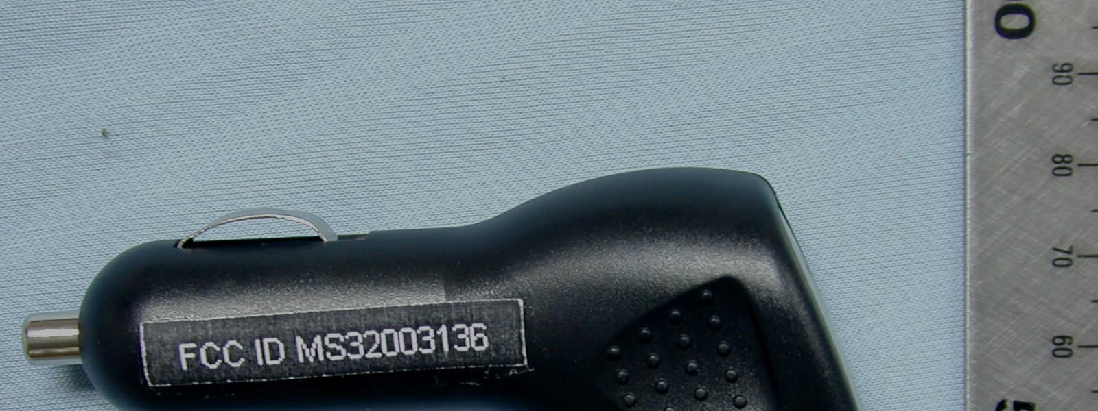
MS32003136
Apr 17, 20052003 Falcon CLA Model No.: 2003-136
Equipment Class
JBP - Part 15 Class B Computing Device Peripheral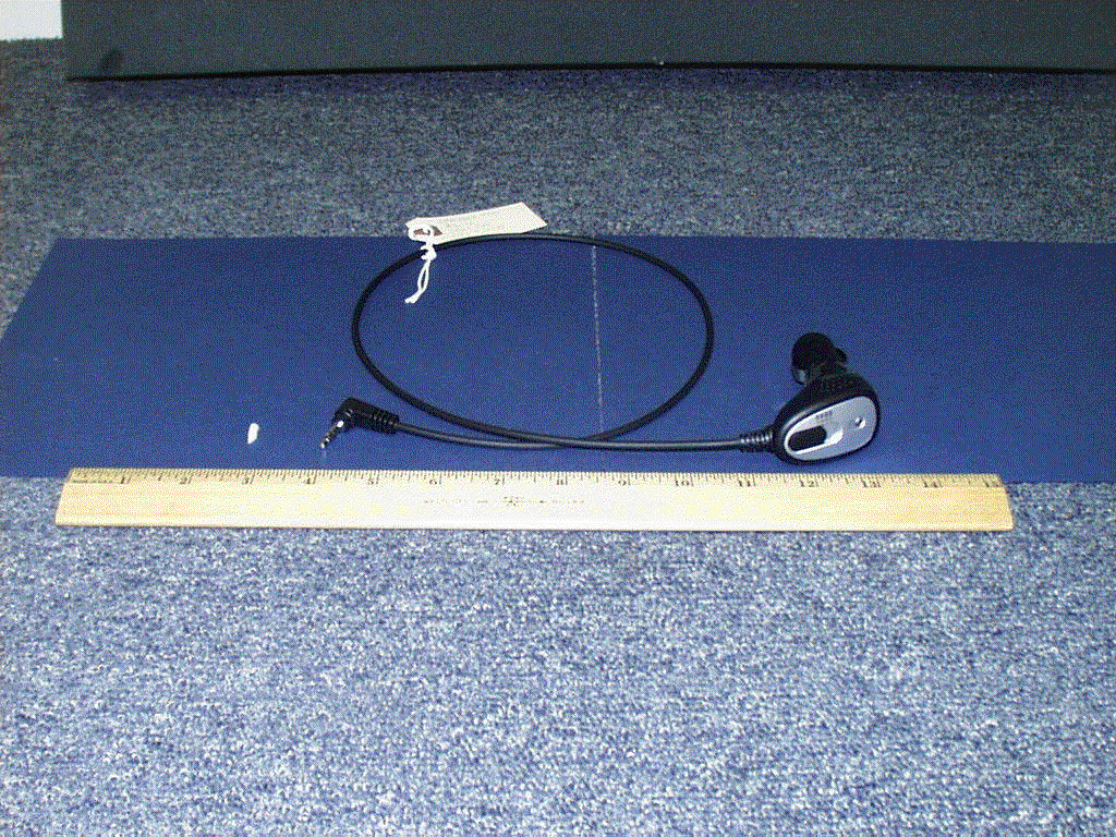
MS3UFM2003
Jul 06, 2004Wireless MP3 adapter
Equipment Class
DXX - Part 15 Low Power Communication Device Transmitter