MSJ50117R49 MHz RECEIVER
Kin Sun Electronics Ltd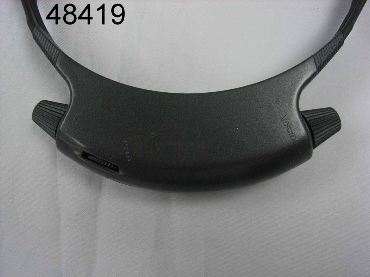
Click to zoom
Application Details
- Equipment Class
- CYY - Communications Receiver used w/Pt 15 Transmitter
- Date of Grant
- Sep 26, 2007
- Application Purpose
- Original Equipment
- Date of Application
- Sep 26, 2007
- Equipment Note
- 49 MHz RECEIVER
- Frequency Range
- 49.82000000 - 49.90000000
- Company
- Kin Sun Electronics Ltd
- Country
- Hong Kong
Documents & Files
Document Text
Text extracted from the exhibit documents filed with the FCC. Open a document above to read the original.
Operational Description
Circuit Description Product: Wireless Head Phone Model: 50117 In reception mode 1. 49MHz V HF, consisting of ANT,Q101,Q102 and CRYSTAL XD01, is Coupled to IC 101 13 pin of IF amplifier via C111 Capacitance. 2. Thus, IC101 13 PIN is the IF amplifier input terminal. Audio signal, given out from IC11 and amplified by IC 102 power amplifier, turns into sound through speaker. Antenna and Ground Circuitry: This unit, making use of an internal antenna which inputs signal through capacitance coupled. powered with DC 3.7 V without external ground. I In transmission mode 49 MHz oscillator consisting of J1 audio input, J2 micro input and X1 crystal Q1 input is output to Q02 transmitter. 1. Thus, Q02, Q03 and CF1 are combined to be a transmitter to transmit through ANT. 2. J1 audio input and J2 micro input control strength of LED indicator through U1. Charging circuit consisting of J3, ZD101 and Q101, Q102 provides charging function. 3. Antenna and ground: The unit, making use of an external retractable 35 cm long antenna, gives out signal through CF1. it works with the ground of circuitry board and without external ground, powered by DC12 V.
Contact Information
Applicant
Tony Pak(Manager)
Test Firm
SGS IECC LimitedJeffery Chen
Technical Specifications
| # | Rule Parts | Frequency Range | Power Output |
|---|---|---|---|
| 1 | 15B | 49.82 MHz - 49.9 MHz | - |
Other Applications from Kin Sun Electronics Ltd
MSJ50117T
Sep 26, 200749MHz TRANSMITTER
Equipment Class
DXX - Part 15 Low Power Communication Device Transmitter
MSJK-2002DW1-WB
May 15, 2006AM/FM/Weather Band Broadcast Receiver
Equipment Class
CXX - Communications Rcvr for use w/ licensed Tx and CBs
MSJK-2004-8
Mar 31, 2005Weather band radio w/ AM/FM/TV1/TV2 & Dynamo
Equipment Class
CXX - Communications Rcvr for use w/ licensed Tx and CBs
MSJK-2002-6TV
Nov 06, 2002Transmitter
Equipment Class
DXX - Part 15 Low Power Communication Device TransmitterMSJ96-A000001
Aug 06, 1997CXX - Communications Rcvr for use w/ licensed Tx and CBs
Equipment Class
CXX - Communications Rcvr for use w/ licensed Tx and CBs