MTD-0021Duress Device with Transceiver
TimeKeeping Systems Inc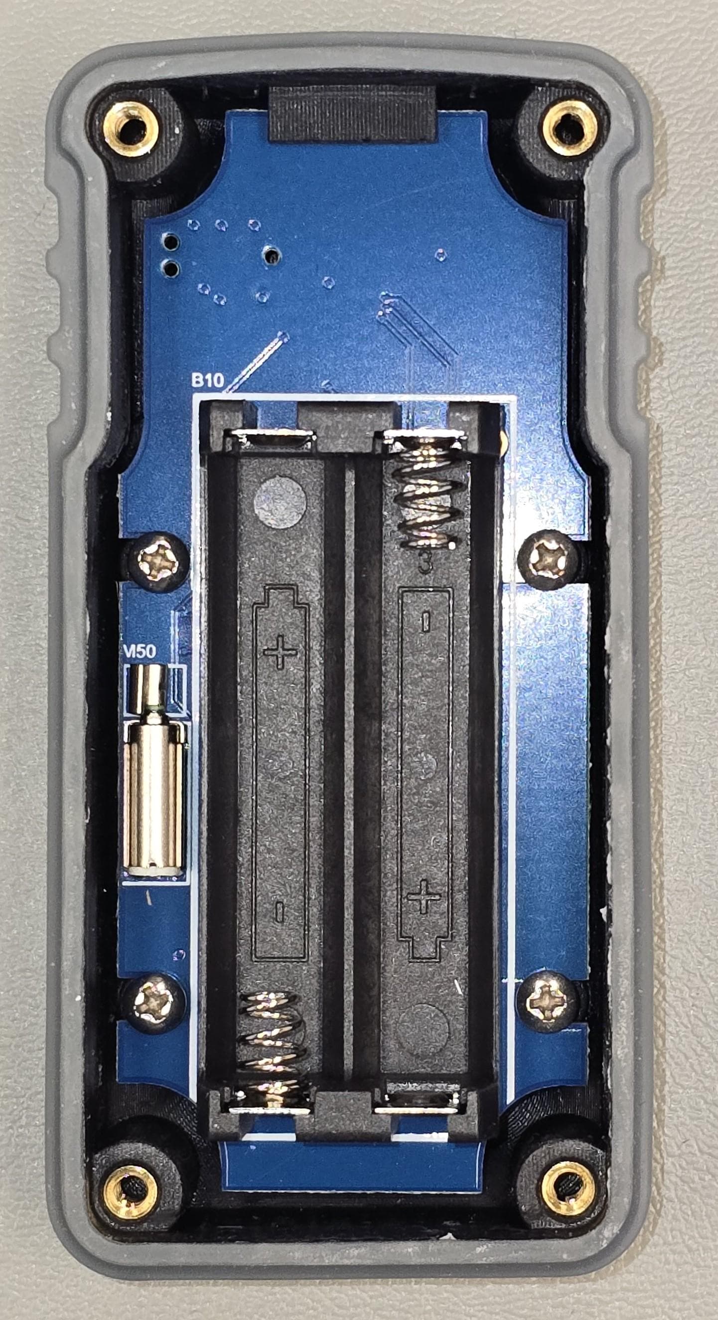
Click to zoom
Application Details
- Equipment Class
- DXX - Part 15 Low Power Communication Device Transmitter
- Date of Grant
- Aug 14, 2024
- Application Purpose
- Original Equipment
- Date of Application
- Aug 14, 2024
- Equipment Note
- Duress Device with Transceiver
- Frequency Range
- 2402.00000000 - 2480.00000000
- Company
- TimeKeeping Systems Inc
- Country
- United States
Documents & Files
Document Text
Text extracted from the exhibit documents filed with the FCC. Open a document above to read the original.
Users Manual
GUARD1 /tracking Duress Device User's Manual Version 12 Guard1|Duress Device Updated: July, 2024 MODEL: DD-0021 | HVIN: DD-0021 | FCC ID: MTD-0021 | IC: 12375A-0021 Introduction The Duress Device is a portable device that is worn on a duty belt or lanyard by officers, staff, or visitors. It monitors their status and transmits tracking and status information to a control room monitor. It can be used to signal an emergency. The Duress Device sends a signal to the GUARD1 Tracking system once each second. If this signal is interrupted, the Panic button is pressed, or if a secondary condition is detected, an alert is raised in the GUARD1 Tracking system. Batteries The Duress Device uses two AAA batteries. These are field replaceable, non-rechargeable 1.5 Volt alkaline batteries. They can be replaced by removing the four screws on the back of the device and separating the halves of the housing. Using the Duress Device The Duress Device has two buttons. The large Panic button is for sending a panic alert. The small Test button is for changing the device mode. It has one LED, in the center of the Panic button, which is used to confirm it is operating and to display battery status. The Duress Device has a vibration motor and a beeper. Either one of these may be enabled, or both. Off Duty Off Duty is a low-power mode for when the device is not in use. The LED flashes green once every 30 seconds (or orange if the battery is low). There is no alert condition, and the device does not beep or vibrate. To place the device in Off Duty mode, detach it from the holster and press the Test button twice. The device will beep to confirm. Test If you press the Test button while the Duress Device is in Off Duty or On Duty mode and detached from its holster, it will beep and vibrate while it runs a circuit test. The LED will blink orange, then turn green to indicate a successful test. Press the Panic button once to switch to On Duty mode, or press the Test button again to switch to Off Duty mode. If the test fails, the device will still enter On Duty mode but will notify the user with a “fail” beep and orange LED and will send an alert. The test can be repeated which may resolve the error. If the test fails three times, the device will be placed in a permanent error condition and should be returned to TimeKeeping Systems. On Duty On Duty is the normal operational state of the Duress Device. There is no alert condition, and it is monitoring your status. The LED flashes green once per second. If the battery is low, the LED flashes orange once per second. ✹ ♩ STATUS Single beep entering Active mode Guard1|Duress Device Updated: July, 2024 MODEL: DD-0021 | HVIN: DD-0021 | FCC ID: MTD-0021 | IC: 12375A-0021 The LED will indicate the battery status: green for good, orange for low, and red for discharged. If the battery is low or discharged, replace the batteries immediately. Warning The Duress Device will signal a warning to the user for thirty seconds if one of these conditions exists: • The device is not vertical • There has been no motion • The device has been removed from the holster To stop the warning, correct the condition causing it. ✹ ♪ STATUS One beep every four seconds The Duress Device will beep and/or vibrate once every four seconds. The LED flashes once each second. As in On Duty mode, the LED color indicates the battery status. Some of these conditions may not be enabled and/or the warning period may be different, depending on the settings. Secondary Alert If a Warning condition exists for more than thirty seconds, the Duress Device will signal an alert. To stop the alert, correct the condition causing it. ✹ ♬ STATUS Double beep once every four seconds The Duress Device will beep twice and/or vibrate twice, and the LED flashes once each second. As in On Duty mode, the LED color indicates the battery status. Some of these conditions may not be enabled and/or the warning period may be different, depending on the settings. If the Duress Device goes into Secondary Alert mode, the user should contact the Control Room as soon as possible to apprise them of the situation so they can take action, including acknowledging any generated alerts and turning off any emergency signals or sirens. Panic Alert To signal an emergency, press the Panic button. This indicates that an emergency exists and you are summoning help immediately. The alert will continue until five minutes have passed, or you cancel the alert. ✹ ♬ STATUS Double beep once per second The Duress Device will beep and/or vibrate once a second. The LED flashes once each second. As in Active mode, the LED color indicates the battery status. Pressing the Panic button again extends the panic alert. The Duress Device will signal an alert for five minutes from the last button press. If the Duress Device goes into Panic Alert mode, the user should contact the Control Room as soon as possible to apprise them of the situation so they can take action, including acknowledging any generated alerts and turning off any emergency signals or sirens. Guard1|Duress Device Updated: July, 2024 MODEL: DD-0021 | HVIN: DD-0021 | FCC ID: MTD-0021 | IC: 12375A-0021 To cancel the Panic Alert, press and hold the Panic and Test buttons at the same time for five seconds. Very Low Battery In normal operation, the battery LED will flash green, then orange as the battery is depleted. After that the Duress Device will enter Very Low Battery mode. ✹ ♪ STATUS Short "chirp" once every minute The Duress Device will give a distinctive "chirp", and the LED will flash, once every sixty seconds In Very Low Battery mode, you can still use the button to signal a Panic Alert. The Duress Device will transmit a Panic Alert for as long as the battery lasts. Secondary Alerts are disabled in Very Low Battery mode. The Duress Device may continue to operate in Very Low Battery mode, but in this mode you cannot rely on continued operation and the batteries should be replaced immediately. FCC Statements Pu…
Text truncated - open the document above for the full version.
Attestation Statements
Test Lab Attestation Letter Date of Test: June 4-28, 2024 Applicant Name: TimeKeeping Systems, Inc. FCC ID: MTD-0021 Test Item: Duress Device with Transceiver Model: DD-0021 Name of Engineer Performing Test: Joseph Strzelecki, Chris D’Alessio Radiometrics Midwest Corporation Statement of Compliance: Radiometrics declares that this Unit has been tested in accordance with the test method identified in this test report and that we observed it being tested. We also declare that the Unit complies with the relevant limits. All instrumentation and accessories used to test this unit for compliance to the indicated test method are calibrated regularly in accordance with ISO 17025:2017 requirements by laboratories accredited by A2LA, NVLAP, or ACLAS for the measurement parameters. The measurements were made at: Radiometrics Midwest Corporation 12 Devonwood Avenue Romeoville IL 60446 Test Lab Witness- Joseph Strzelecki Signature of Test Lab Witness: Full Name, Typed: Joseph R Strzelecki Title of Witness: Senior EMC Engineer Email Address: [email protected] Phone No.: 815-293-0772 Test Lab Stamp:
Cover Letter(s)
Page 1 of 1 RP-9992 12 Devonwood Ave SOL VING A WAV E OF EMI COMP LIANCE PR OB LE MS Romeoville, IL 60446 Tel: (815) 293-0772 Federal Communications Commission July 31, 2024 Authorization and Evaluation Division 7435 Oakland Mills Rd. Columbia, MD 21046 Reference FCC ID: MTD-0021 Organization: TimeKeeping Systems, Inc. 1. Long Term Confidentiality In accordance with Sections 0.457 and 0.459 of the Commission’s Rules, (TimeKeeping Systems, Inc.) hereby requests long-term confidential treatment of information accompanying this application as outlined below: Exhibit Type File Name Circuit Schematics 7 TimeKeeping Duress 12_Holster_Schematics 9992 Block Diagram 8 TimeKeeping Duress-12_Holster BlockDiagram 9992 EUT description (Operational Description) 10 TimeKeeping Duress 12 Holster Operational Description 9992 The above materials contain proprietary and confidential information not customarily released to the public. The public disclosure of these materials provides unjustified benefits to its competitors in the market. They are considered confidential trade secrets. Pursuant to DA04-1705 June 15, 2004 of the Commission’s public notice, we also request temporary confidential treatment of information accompanying this application as outlined below for 180 days: Exhibit Type File Name Internal Photos 4a TimeKeeping Internal Photos 9992 Authorized Signature Joseph Strzelecki Senior EMC Engineer Radiometrics Midwest Corporation Authorized Agent for TimeKeeping Systems, Inc..
External Photos
Page 1 of 4 RP-9992 External EUT Photographs Front View Page 2 of 4 RP-9992 Rear View: Belt clip removed The FCC and Canada ID’s will be molded onto the housing of the EUT. The above shows the location of where the information will appear on the case. The actual text will appear as follows: Page 3 of 4 RP-9992 Rear View: Cover removed Page 4 of 4 RP-9992 Left Side Right Side Top Bottom
ID Label/Location Info
Page 1 of 3 RP-9992 ID Label/Location Photograph showing placement of Label The FCC and Canada ID’s will be molded onto the housing of the EUT. The above shows the location of where the information will appear on the case. The actual text will appear as follows: Radiometrics Midwest Corporation (815) 293-0772 – [email protected] Drawing of label Radiometrics Midwest Corporation (815) 293-0772 – [email protected]
RF Exposure Info
Page 1 of 1 RP-9992 RF Exposure FCC ID: MTD-0021 These calculations are based on the highest EIRP possible from the EUT considering maximum power output and antenna gain or the highest EIRP possible from the EUT, measured in the radiated mode. A 1% duty cycle was used for the calculations even though the duty cycle is lower in actual use. KDB 447498 D04 Interim General RF Exposure Guidance v01, Section 2.1.2: 1mW Test Exemption As per Section 2.1.2: of KDB 447498 D04 v01: “Per § 1.1307(b)(3)(i)(A), a single RF source is exempt RF device (from the requirement to show data demonstrating compliance to RF exposure limits, as previously mentioned) if the available maximum time- averaged power is no more than 1 mW, regardless of separation distance. This exemption applies to all operating configurations and exposure conditions, for the frequency range 100 kHz to 100 GHz, regardless of fixed, mobile, or portable device exposure conditions. This is a standalone exemption, and it cannot be applied in conjunction with any other test exemption.” Band Freq. (MHz) Max Power EIRP (dBm) Tune up Tolerance (dB) Max Power (mW) Duty Cycle % Average EIRP (mW) 2.4G 2402 14.1 1.5 36.3 1 0.36 As can be seen in the table above, the average power is less than 1 mW, therefore it is exempt from testing. The product is stand-alone transmitter SAR EXCLUSION RESULT In accordance with FCC KDB Publication 447498 D01 V05R06 Clause 4.3.1 a), The 1‐g SAR test exclusion thresholds for 100 MHz to 6 GHz at test separation distances ≤ 50 mm are determined by: [(max. power, mW)/(min. separation distance, mm)] x [√f(GHz)] ≤ 3.0 for 1‐g extremity SAR, where ‧ f(GHz) is the RF channel transmit frequency in GHz MHz Max EIRP Power dBm Tune up tolerance dB Duty Cycle % EIRP Average mW Min Sep mm SAR Exc Threshold 4.3.1 a) Limit 1-g Result 2402 13.70 1.5 1.0 0.331 5 0.1026 3.0 Exempt Judgement: The product is exempt from SAR testing
Test Report
Application Report 2.4-GHz Inverted F Antenna ABSTRACT This document describes a printed-circuit board (PCB) antenna design that can be used with all 2.4-GHz transceivers and transmitters from Texas Instruments ™ . The maximum gain when used on the reference board is measured to be +3.3 dBi, and the overall size requirements for this antenna are 25.7 × 7.5 mm (not including ground plane). Table of Contents 1 Description of the antenna Design........................................................................................................................................2 2 Measurement Results.............................................................................................................................................................3 2.1 Radiation Pattern...............................................................................................................................................................3 2.2 Reflection.........................................................................................................................................................................10 2.3 Bandwidth.........................................................................................................................................................................11 3 Summary................................................................................................................................................................................11 4 References.............................................................................................................................................................................11 5 Revision History...................................................................................................................................................................12 Trademarks Texas Instruments ™ is a trademark of Texas Instruments. All trademarks are the property of their respective owners. www.ti.comTable of Contents SWRU120D – APRIL 2007 – REVISED JANUARY 2019 Submit Document Feedback 2.4-GHz Inverted F Antenna1 Copyright © 2021 Texas Instruments Incorporated 1 Description of the antenna Design It is important to make an exact copy of the antenna dimensions to obtain optimum performance. The easiest approach to implement the antenna in a PCB CAD tool is to import the antenna layout from a gerber file or a DXF file. Such files are included in CC2430DB reference design [1]. The gerber file is called Inverted_F_Antenna.spl and the DXF file is called Inverted_F_Antenna.dxf. If the antenna is implemented on a PCB that is wider than the antenna, avoid placing components or having a ground plane close to the end points of the antenna. If the CAD tool being used does not support importing gerber or DXF files, see Figure 1-1 and Table 1-1. The antenna impedance is tuned to 50 ohm on the reference board. The impedance will however be affected by different size and shape of the ground plane, objects in the antenna nearfield such as mechanical assemblies (housing, batteries, etc.), PCB thickness, PCB material and so on. It is therefore recommended to add a pi-network close to the antenna feedpoint for impedance matching. The results presented in this document are based on an antenna implemented on a PCB with a 1-mm thickness using standard FR-4 material. Figure 1-1. IFA Dimensions Table 1-1. IFA Dimensions H15.70 mmW20.46 mm H20.74 mmL125.58 mm H31.29 mmL216.40 mm H42.21 mmL32.18 mm H50.66 mmL44.80 mm H61.21 mmL51.00 mm H70.80 mmL61.00 mm H81.80 mmL73.20 mm H90.61 mmL80.45 mm W11.21 mm Description of the antenna Designwww.ti.com 22.4-GHz Inverted F AntennaSWRU120D – APRIL 2007 – REVISED JANUARY 2019 Submit Document Feedback Copyright © 2021 Texas Instruments Incorporated 2 Measurement Results All of the results presented in this section are based on measurements performed with the CC2430DB [1] evaluation board. 2.1 Radiation Pattern Figure 2-1 shows how to relate all of the radiation patterns to the orientation of the antenna. The radiation patterns were measured with the CC2430 device programmed to 0-dBm output power. Figure 2-1. Relating Antenna to Radiation Patterns www.ti.comMeasurement Results SWRU120D – APRIL 2007 – REVISED JANUARY 2019 Submit Document Feedback 2.4-GHz Inverted F Antenna3 Copyright © 2021 Texas Instruments Incorporated Figure 2-2 shows the XY plane vertical polarization. Figure 2-2. XY Plane–Vertical Polarization Measurement Resultswww.ti.com 42.4-GHz Inverted F AntennaSWRU120D – APRIL 2007 – REVISED JANUARY 2019 Submit Document Feedback Copyright © 2021 Texas Instruments Incorporated Figure 2-3 shows the XY plane horizontal polarization. Figure 2-3. XY Plane–Horizontal Polarization www.ti.comMeasurement Results SWRU120D – APRIL 2007 – REVISED JANUARY 2019 Submit Document Feedback 2.4-GHz Inverted F Antenna5 Copyright © 2021 Texas Instruments Incorporated Figure 2-4 shows the XZ plane vertical polarization. Figure 2-4. XZ Plane–Vertical Polarization Measurement Resultswww.ti.com 62.4-GHz Inverted F AntennaSWRU120D – APRIL 2007 – REVISED JANUARY 2019 Submit Document Feedback Copyright © 2021 Texas Instruments Incorporated Figure 2-5 shows the XZ plane horizontal polarization. Figure 2-5. XZ Plane–Horizontal Polarization www.ti.comMeasurement Results SWRU120D – APRIL 2007 – REVISED JANUARY 2019 Submit Document Feedback 2.4-GHz Inverted F Antenna7 Copyright © 2021 Texas Instruments Incorporated Figure 2-6 shows the YZ plane vertical polarization. Figure 2-6. YZ Plane–Vertical Polarization Measurement Resultswww.ti.com 82.4-GHz Inverted F AntennaSWRU120D – APRIL 2007 – REVISED JANUARY 2019 Submit Document Feedback Copyright © 2021 Texas Instruments Incorporated Figure 2-7 shows the YZ plane horizontal polarization. Figure 2-7. YZ Plane–Horizontal Polarization www.ti.comMeasurement Results SWRU120D – APRIL 2007 – REVISED JANUARY 2019 Submit Document Feedback 2.4-GHz Inverted F Antenna9 Copyright © 202…
Text truncated - open the document above for the full version.
Test Report
Electromagnetic Compatibility Test Report Tests Performed on a TimeKeeping Systems, Inc. Duress Device, Model DD-0021 Radiometrics Document RP-9992 Product Detail: FCC ID: MTD-0021 IC: 12375A-0021 Equipment type: Security Device with Transceiver Test Standards: US CFR Title 47, Chapter I, FCC Part 15 Subpart C FCC Part 15 CFR Title 47: 2024 Canada ISED; RSS-210, Issue 10: 2019 as required for Category I Equipment IC RSS-GEN Issue 5: 2018 This report concerns: Original Grant for Certification FCC Part 15.249 Tests Performed For: Test Facility: TimeKeeping Systems, Inc. 30700 Bainbridge Rd., Suite H Solon, OH 44139 Radiometrics Midwest Corporation 12 Devonwood Avenue Romeoville, IL 60446-1349 (815) 293-0772 Test Date(s): June 6-28, 2024 Document RP-9992 Revisions: Rev. Issue Date Revised By 0 August 2, 2024 Testing of: TimeKeeping Systems, Inc., Model DD-0021, Duress Device RP-9992 Rev. 0 Radiomet.com Page 2 of 16 Table of Contents 1.0 ADMINISTRATIVE DATA ............................................................................................................... 3 2.0 TEST SUMMARY AND RESULTS ................................................................................................. 3 2.1 RF Exposure Compliance Requirements .................................................................................... 4 3.0 EQUIPMENT UNDER TEST (EUT) DETAILS ................................................................................ 4 3.1 EUT Description .......................................................................................................................... 4 3.1.1 FCC Section 15.203 & RSS-GEN Antenna Requirements .................................................... 4 4.0 TESTED SYSTEM DETAILS .......................................................................................................... 4 4.1 Tested System Configuration ...................................................................................................... 4 4.2 EUT Operating Modes ................................................................................................................ 5 4.3 Special Accessories .................................................................................................................... 5 4.4 Equipment Modifications ............................................................................................................. 5 5.0 TEST SPECIFICATIONS ............................................................................................................... 5 6.0 TEST PROCEDURE DOCUMENTS ............................................................................................... 5 7.0 RADIOMETRICS’ TEST FACILITIES ............................................................................................. 5 8.0 DEVIATIONS AND EXCLUSIONS FROM THE TEST SPECIFICATIONS ...................................... 6 9.0 CERTIFICATION ............................................................................................................................ 6 10.0 TEST EQUIPMENT TABLE .......................................................................................................... 6 11.0 TEST SECTIONS ......................................................................................................................... 7 11.1 Radiated RF Emissions............................................................................................................. 7 11.1.1 Field Strength Calculation ................................................................................................... 7 11.1.2 Duty Cycle .......................................................................................................................... 8 11.1.3 Radiated Emissions Test Results ....................................................................................... 8 11.2 Occupied Bandwidth Data ....................................................................................................... 14 11.2.1 Measurement Instrumentation Uncertainty ....................................................................... 16 12.0 REVISION HISTORY ................................................................................................................. 16 Notice: This report must not be reproduced (except in full) without the written approval of Radiometrics Midwest Corporation. Testing of: TimeKeeping Systems, Inc., Model DD-0021, Duress Device RP-9992 Rev. 0 Radiomet.com Page 3 of 16 1.0 ADMINISTRATIVE DATA Equipment Under Test: A TimeKeeping Systems, Inc., Duress Device Model: DD-0021 Serial Number: 004 This will be referred to as the EUT in this Report Date EUT Received at Radiometrics: Test Date(s): June 3, 2024 June 6 to 28, 2024 Test Report Written and Authorized By: Test Witnessed By: Joseph Strzelecki Senior EMC Engineer The tests were not witnessed by personnel from TimeKeeping Systems, Inc. Radiometrics’ Personnel Responsible for Test: EUT Checked By: 08/02/2024 Date Joseph Strzelecki Senior EMC Engineer NARTE EMC-000877-NE Chris D’Alessio EMC Technician Joseph Strzelecki Chris D’Alessio Radiometrics 2.0 TEST SUMMARY AND RESULTS The EUT (Equipment Under Test) is a Duress Device, Model DD-0021, manufactured by TimeKeeping Systems, Inc. The detailed test results are presented in a separate section. The following is a summary of the test results. Emissions Tests Results Environmental Phenomena Frequency Range Basic Standard Test Result RF Radiated Emissions 30-25,000 MHz RSS-210 & FCC Part 15.249 Pass Conducted Emissions, AC Mains 0.15 - 30 MHz RSS-210 & FCC Part 15.207 Pass Occupied Bandwidth Test Fundamental Freq. RSS-GEN & FCC Part 15 Pass IEC 17025 Decision Rule: The declaration of pass or fail is based on the specifications listed above. The declaration of pass or fail did not consider measurement uncertainty. Testing of: TimeKeeping Systems, Inc., Model DD-0021, Duress Device RP-9992 Rev. 0 Radiomet.com Page 4 of 16 2.1 RF Exposure Compl…
Text truncated - open the document above for the full version.
Test Setup Photos
Page 1 of 3 RP-9992 Test Setup Photographs Photographs of Radiated Emissions Test Setup 30-200 MHz 200 to 1000 MHz Page 2 of 3 RP-9992 1-18 GHz Page 3 of 3 RP-9992 Direct measurement Test Setup
Contact Information
Applicant
Barry Markwitz(President)
Test Firm
Radiometrics Midwest Corp.Joseph Strzelecki
Technical Specifications
| # | Rule Parts | Frequency Range | Power Output |
|---|---|---|---|
| 1 | 15C | 2.40 GHz - 2.48 GHz | - |
Other Applications from TimeKeeping Systems Inc
MTD-0030
Jul 02, 2026Tracking Device with Transceiver
Equipment Class
DXX - Part 15 Low Power Communication Device Transmitter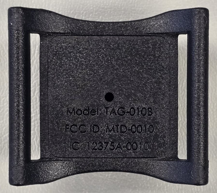
MTD-0010
Sep 11, 2024Tracking Device with Transceiver
Equipment Class
DXX - Part 15 Low Power Communication Device TransmitterMTD-0009
Feb 19, 2020Model TAG-008 ID badge tag
Equipment Class
DXX - Part 15 Low Power Communication Device TransmitterMTDBR07
May 20, 1996CYY - Communications Receiver used w/Pt 15 Transmitter
Equipment Class
CYY - Communications Receiver used w/Pt 15 TransmitterMTDRW07
May 20, 1996Bar Code Scanner Transmitter
Equipment Class
DXX - Part 15 Low Power Communication Device Transmitter