MU7FPCWL01Spread Spectrum Tranceiver
Fujitsu PC Corporation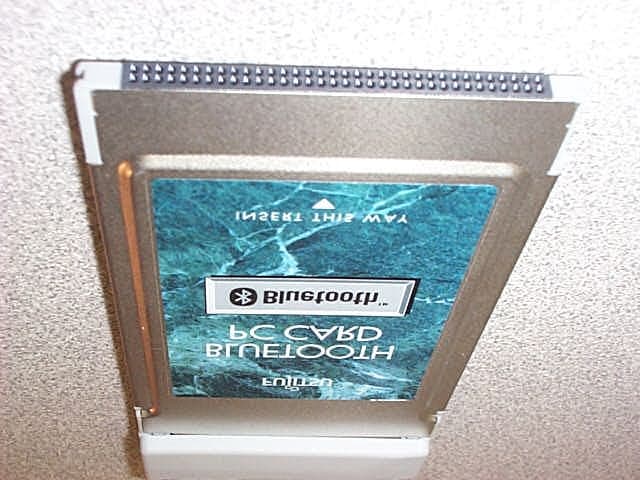
Click to zoom
Application Details
- Equipment Class
- DSS - Part 15 Spread Spectrum Transmitter
- Date of Grant
- Apr 02, 2001
- Application Purpose
- Original Equipment
- Date of Application
- Apr 02, 2001
- Equipment Note
- Spread Spectrum Tranceiver
- Frequency Range
- 2402.00000000 - 2480.00000000
- Company
- Fujitsu PC Corporation
- Country
- United States
Documents & Files
Document Text
Text extracted from the exhibit documents filed with the FCC. Open a document above to read the original.
Users Manual
The Bluetooth TM PC Card allows you to use your Fujitsu computer to perform wireless communications with other Bluetooth-compatible computers and with the optional Fujitsu Modem Station. This guide contains information on installing, removing, and using your BlueTooth PC Card with your computer. Before using the PC Card, please read this user’s guide carefully to familiarize yourself with the proper use of the card and Bluetooth technology. In addition to this manual, refer to the manual for your computer and the Fujitsu Modem Station, if used. INSTRUCTIONS Bluetooth ™ PC Card Installation and User’s Guide Fujitsu PC Corporation 2 CAUTION This device could malfunction in the event of a voltage sag or momentary drop in voltage because of lightning or electrical disturbance. To protect your personal computer against voltage sag, it is recommended to use an uninterruptible power supply (UPS). The frequency band used for this device is the same as for some types of industrial, scientific, and medical equipment, including microwave ovens, as well as on-premises radio stations (subject to a license) for identification of mobile units, e.g., radio stations installed in production lines in factories, and other application-specific low-output radio stations (not subject to a license). Before using this device, make sure that there is no on- premises radio stations for identification of mobile units or other application-specific low-output radio stations near the device. In the event this device causes radio frequency interference to an on-premises radio station for identification of mobile units, immediately change the frequency used or break off connection, and consult FM Information Service about preventive measures against radio frequency interference (for example, installation of partitions). If you encounter a problem using this device, including radio frequency interference from this device to an application- specific low-output radio station for identification of mobile units, contact FM Information Service for help. 3 About the warranty Make sure the warranty card included with this product is filled out correctly. The warranty may not apply unless the warranty card is filled out correctly and completely. If you find it incorrect or incomplete, contact your seller immedi- ately. Store the warranty card in a safe place. Safety Instructions For safe use of your PC Card, always follow the instructions below. This guide uses graphical symbols to highlight instructions that you must follow to avoid personal injury or damage to property when using the PC Card. Before reading this guide, read the following explanations carefully to fully understand the meanings of these symbols. WARNING The warning icon highlights information that can be hazardous to you, your computer, or your files. Please read all warnings carefully. POINT The point icon highlights information that will enhance your understanding of the subject material. 4 MANDATORY: * Remove the Bluetooth PC Card from your computer or turn off your computer in a hospital or near a medical electronic system. Don’t bring your computer with the PC Card connected in an operating room, particularly in a CCU (cardiac care unit), otherwise radio waves transmitted by the PC Card could affect medial electric systems and cause an accident in the worst case. MANDATORY: * Keep your computer at least 22 cm away from a pacemaker, otherwise Radio waves transmitted by the PC Card could affect its functioning and cause an accident by its malfunction. MANDATORY: * Remove the Bluetooth PC Card from your computer or turn off your computer in any crowded place where there may be persons wearing a pacemaker, for example, in a jammed train. Radio waves transmitted by the PC Card could affect the functioning of pacemakers. MANDATORY: * Remove the Bluetooth PC Card from your computer or turn off your computer on an airplane. The PC Card could impair the safe navigation of an airplane. MANDATORY: * Don’t use the Bluetooth PC Card during driving. Failure to do so could impair the safe driving and CAUTION The caution symbol highlights information that is important to your safety, to the safe operation of your computer, or to the integrity of your files. Please read all caution information carefully. 5 result in an accident in the worst case. When using the PC Card, always park your car in a safe place. MANDATORY: * Keep the plastic bag used for packing out of the reach of children. The plastic bag could choke a child if he or she put it in his or her mouth or put it over his or her face. EXPLOSION: * Remove the Bluetooth PC Card from your computer where it can be exposed to flammable gases, for example, gas stations, otherwise it could cause an explosion or fire. PROHIBITION: * Don’t use the Bluetooth PC Card near an automatic door or fire alarm, otherwise radio waves trans- mitted by the PC Card could affect its automatic control unit and cause an accident by its malfunction. DON’T DISASSEMBLE: * Never disassemble, repair, or modify the Bluetooth PC Card. Touching internal compo- nents could cause you to get an electric shock. PROHIBITION: * Don’t touch the Bluetooth PC Card unnecessarily when it is in use, otherwise it could fail or cause an electric shock. PROHIBITION: * Don’t place a glass or flower vase containing liquid near your computer. Liquid could cause an electric shock if it gets in the computer. PROHIBITION: * Don’t install your computer on a slanted or unsteady surface, or where it will be exposed to vibration, otherwise your computer could fall or topple over, causing bodily injury. 6 PROHIBITION: * When inserting the PC Card in a PC Card slot or ejecting the card from it, don’t put your finger into the slot, otherwise you could get an injury to your finger. PROHIBITION: * The PC Card may be heated up immedi- ately after it was used for a long time. To avoid a burn, don’t remove it from your computer immediately after use. PROHIBITION: * Don’t bring any…
Text truncated - open the document above for the full version.
Block Diagram
System block diagram Bluetooth TM Chip Flash Memory Tx Balun Low Noise Amplifier Tx/Rx RF Switch Band Pass Filter Crystal Power Amplifier Power Control Switch Control Data Address Tx ARx PCMCIA Connector Antenna Tx B PCMCIA - UART Interface ASI C Serial EEPROM Crystal
Cover Letter(s)
C:\WINDOWS\TEMP\probonholdemail.doc TIMCO TIMCOTIMCO TIMCO ENGINEERING INC. 849 NW State Road 45 Newberry, Florida 32669 http://www.timcoengr.com 888.472.2424 F 352.472.2030 email: tei@t imcoengr.com 3 April 2001 FCC SUBJECT: FUJITSU PC CORPORATION FCC ID:MU7FPCWL01 To Whom It May Concern: This EUT is a PCMCIA Card that is used in a pin computer and will always be more than 20cm from any user. The first page of the test report says that the power output is 97milliwatts, this is an error. The correct power is 6.7milli Watts. The report and the exhibits are some what fragmented because that is the way we received it. This EUT is a “Blue Tooth” product and we are told that it is compliant with this requirement. It has 79 hopping channels with a 20dB bandwidth of 325kHz. The EUT has a dwell time of 152milli seconds. Sincerely, Sid Sanders
External Photos
Fujitsu PC Corp. FCC ID #: MU7FPCWL01 Test Report #: FUJ-0101-2849-TCB Prepared for Fujitsu PC Corp. Prepared by EMC Compliance Management GroupPage 26 of 30 ATTACHMENT M – SAMPLE PHOTOS EUT Photo with Antenna Retracked EUT Fujitsu PC Corp. FCC ID #: MU7FPCWL01 Test Report #: FUJ-0101-2849-TCB Prepared for Fujitsu PC Corp. Prepared by EMC Compliance Management GroupPage 27 of 30 Fujitsu PC Corp. FCC ID #: MU7FPCWL01 Test Report #: FUJ-0101-2849-TCB Prepared for Fujitsu PC Corp. Prepared by EMC Compliance Management GroupPage 28 of 30
ID Label/Location Info
Fujitsu PC Corp. FCC ID #: MU7FPCWL01 Test Report #: FUJ-0101-2849-TCB Prepared for Fujitsu PC Corp. Prepared by EMC Compliance Management GroupPage 29 of 30 ATTACHMENT N – PROPOSED FCC ID LABEL AND LOCATION Proposed FCC ID Label Proposed FCC ID Location
Internal Photos
Fujitsu PC Corp. FCC ID #: MU7FPCWL01 Test Report #: FUJ-0101-2849-TCB Prepared for Fujitsu PC Corp. Prepared by EMC Compliance Management GroupPage 29 of 32 ATTACHMENT M – SAMPLE PHOTOS (INTERNAL) Fujitsu PC Corp. FCC ID #: MU7FPCWL01 Test Report #: FUJ-0101-2849-TCB Prepared for Fujitsu PC Corp. Prepared by EMC Compliance Management GroupPage 30 of 32
Operational Description
The Bluetooth TM PC Card allows you to use your Fujitsu computer to perform wireless communications with other Bluetooth-compatible computers and with the optional Fujitsu Modem Station. This guide contains information on installing, removing, and using your BlueTooth PC Card with your computer. Before using the PC Card, please read this user’s guide carefully to familiarize yourself with the proper use of the card and Bluetooth technology. In addition to this manual, refer to the manual for your computer and the Fujitsu Modem Station, if used. INSTRUCTIONS Bluetooth ™ PC Card Installation and User’s Guide Fujitsu PC Corporation
Schematics
100k R34 100k R29 10k R26 10k R21 10k R24 10k R28 10k R20 R27 10k 4.7k R44 0.1u C28 100k R31 GND GND GND +3 GND +3+3+3 GND GND VCC VCC 0.1u C31 GND X1 15p C10 15p C11 GND 0 R17 TxD /RTS RxD /CTS 4.7k R45 0 R12 0 R14 0 R13 0 R11 0 R15 VCC GND 33 R38 33 R36 33 R40 33 R37 33 R41 33 R42 33 R43 33 R39 C26 0.022u 0.01u C20 10k R23 IC6 1 OUT 2 VDD 3 GND 4 NC 5 CD 1m R2 100k R30 +3 IC2 #POWRST 1 #WAIT 3 A0 5 A1 6 A2 7 A3 8 A4 9 A5 10 A6 11 A7 12 A8 13 A9 14 #CE1 18 #OE 19 #WE 20 #IREQ 21 #IORD 22 #IOWR 23 TEST 26 #INPACK 28 #REG 29 #SPKR 30 #STSCHG 31 #IOIS16 32 RESET 34 CISWE 37 EWESEL 38 E0 40 SCL 42 SDA 43 DCKSL2 47 DCKSL1 48 DCLK 49 DXTALO 52 DXTALI 53 UCKSL2 56 UCKSL1 57 UXTALO 59 UXTALI 60 #WAITM 63 ECLK 64 #POWON 65 AUDIO 66 RDYM 67 #POWDN 68 UCLK 69 #RST 71 RCLK 73 #BAUDOUT 74 #RI 76 #CTS 77 #DCD 78 #DSR 79 #DTR 80 #RTS 81 RXD 82 TXD 83 #OUT2 84 #OUT1 85 D0 89 D1 90 D2 91 D3 92 D4 93 D5 94 D6 95 D7 96 #CISBSY 45 0 R16 0 R10 GNDGND IC2 VCC_2 2 GND_4 4 VCCS_15 15 RMT_SEL 16 GND_17 17 #PMT_EZ 24 VCC_25 25 VCCS_27 27 VCC_33 33 GND_35 35 #PMT_GZ 36 #PMT_WZ 39 GND_41 41 VCC_44 44 I2C_RESET 46 NC_50 50 GND_51 51 VCC_54 54 NC_55 55 GND_58 58 NC_62 62 GND_70 70 VCC_72 72 NC_75 75 GND_86 86 NC_87 87 VCCS_97 97 NC_98 98 NC_99 99 GND_100 100 VCC_61 61 VCC_88 88 GND 0.1u C30 +3 0.1u C29 VCC CN1 D0 30 D1 31 D2 32 D3 2 D4 3 D5 4 D6 5 D7 6 D8 64 D9 65 D10 66 D11 37 D12 38 D13 39 D14 40 D15 41 A0 29 A1 28 A2 27 A3 26 A4 25 A5 24 A6 23 A7 22 A8 12 A9 11 A10 8 A11 10 A12 21 A13 13 A14 14 A15 20 A16 19 A17 46 A18 47 A19 48 A20 49 A21 50 A22 53 A23 54 A24 55 A25 56 RESET 58 #CE1 7 #CE2 42 #REG 61 #OE 9 #WE 15 #IORD 44 #IOWR 45 #IREQ 16 #INPACK 60 #STSCHG 63 #IOIS16 33 #SPKR 62 #VS1 43 #VS2 57 #CD1 36 #CD2 67 VCC_17 17 VCC_51 51 GND_1 1 GND_34 34 GND_35 35 GND_68 68 #WAIT 59 VPP1 18 VPP2 52 IC4 1 A0 2 A1 3 A2 4 GND 5 SDA 6 SCL 7 WP 8 VCC 100k R32 100k R33 IC5 1 2 3 4 5 +3 GND IC11 /1G1 1A1 2 2Y43 1A2 4 2Y3 5 1A3 6 2Y2 7 1A4 8 2Y1 9 GND10 2A1 11 1Y4 12 2A2 13 1Y3 14 2A3 15 1Y2 16 2A4 17 1Y118 /2G19 VCC 20 VCC GND SPI_EN SPI_CSB SPI_CLK SPI_MOSI RESET_IN SPI_MISO SPI_EN GND F-RESET DA[0-7] DA[4] DA[2] DA[7] DA[5] DA[6] DA[0] DA[1] DA[3] AA[0-9] AA[7] AA[4] AA[1] AA[8] AA[9] AA[2] AA[3] AA[0] AA[5] AA[6] AA[5] AA[4] AA[2] AA[0] AA[1] AA[9] AA[3] AA[8] AA[6] AA[7] DA[0] DA[1] DA[2] DA[3] DA[4] DA[5] DA[6] DA[7] Not Fitted : C34,C38,C44,R12,R14,R15,R46,CN3 Circuit Diagram IC1 B1 PIO[3]/12C_SDA C1 RST D1 TX_PWR E1 RF_IN F1 TX_B G1 TX_A H1 VSS_VCO J1 VDD_VCO A2 VDD_PADS B2 PIO[4]/IRQ1 C2 PIO[2]/12CSCL D2 PIO[0]/RXEN E2 VSS_RADIO_E2 F2 VSS_RADIO_F2 G2 VDD_RADIO H2 CP J2 TEST_A A3 UART_TX B3 UART_RX C3 SPI_MISO D3 SPI_CLK E3 PCM_OUT F3 PIO[1]/TXEN G3 PIO[6] H3 TEST_B J3 XTAL_OUT A4 UART_RTS/USB_D+ B4 UART_CTS/USB_D- C4 SPI_MOSI D4 SPI_CSB E4 SCAN_EN F4 PIO[5]/IRQ2 G4 PIO[7] H4 VDD_CORE J4 XTAL_IN A5 VDD_MEN B5 PCM_SYNC C5 PCM_IN D5 PCM_CLK E5 N/C F5 D[11] G5 D[14] J5 VREG A6 VSS_MEN B6 A[6] C6 D[15] D6 A[12] E6 D[13] F6 D[12] G6 D[7] H6 D[6] J6 D[8] A7 WEB B7 A[3] C7 A[9] D7 A[11] E7 A[15] F7 D[10] G7 D[9] H7 D[4] J7 D[5] A8 A[0] B8 A[4] C8 A[7] D8 A[10] E8 A[13] F8 A[17] G8 A[16] H8 D[3] J8 D[2] A9 A[1] B9 A[2] C9 A[5] D9 A[8] E9 A[14] F9 CSB G9 REB H9 D[0] J9 D[1] H5 VSS_CORE A1 VSS_PADS /CTS TxD RxD /RTS RESET_IN C13 8p C15 8p +3 C22 0.01u C23 0.01u C24 0.01u C25 0.01u GND 1k R1 GND GND 10k R22 10k R25 10k R19 +3 GND GND GND +3 +3 27k R9 27k R8 22k R6 22k R5 C34 NF GND +3 C18 1n C33 4.7u +3 GND R3 180k C1 10p C12 330p GND GND C38 NF GND GND GND +3 C40 2p GND C44 NF C5 100p VCC 4.7u C35 +3 IC7 1 GND 2 VDD 3 VOUT 4 NC 5 CE D1 A K R18 330 GND L3 1.2n PIO[1] PIO[0] C3 100p C2 100p GND L8 2.7n 220 R4 GND GND L10 3.9n GND L5 27n C8 100p GND L9 3.3n C14 6p C37 1p GND C7 100p GND 22 R7 PIO[1] L4 1.8n GND C4 100p C27 470p L6 27n GND PIO[0] L7 2.7n C43 1.5p GND GND PIO[1] PIO[0] GND C16 1n GND C17 1n C9 100p GND C36 4.7u MA02305AK IC8 2 3 4 5 6 1 MAX2641EUT-T IC9 23 4 5 6 1 C41 1.6p C39 1.6p 100p C6 C42 0.7p GND R35 2.2 GND SPI_CSB SPI_MOSI SPI_CLK SPI_MISO RESET_IN SPI_CSB SPI_CLK SPI_MOSI SPI_MISO GND +3 PAD1 P1 0.01u C21 GNDGND 0.01u C19 1u C32 GND 1n L2 1n L1 DEA452442BT-3001 FIL1 1 2 3 4 GND IC10 uPG158TB 1 OUT1 2 GND 3 OUT2 4 VCONT2 5 IN 6 VCONT1 CN3 +3 1 RESET_IN 2 SPI_CSB 6 SPI_CLK 5 SPI_MOSI 4 SPI_MISO 3 GND 7 MS-147(06)_MBH2BT02 CN4 C G_1G_2 A +3 39k R46 GND X2 1 2 3 4 GND 10u C45 10uC46 GND F-RESET L11 5.6n IC3 SST39VF400A-70-4C-EK 1 A15 2 A14 3 A13 4 A12 5 A11 6 A10 7 A9 8 A8 9 NC_9 10 NC_10 11 #WE 12 NC_12 13 NC_13 14 NC_14 15 NC_15 16 NC_16 17 A17 18 A7 19 A6 20 A5 21 A4 22 A3 23 A2 24 A1 25 A0 26 #CE 27 VSS_27 28 #OE 29 DQ0 30 DQ8 31 DQ1 32 DQ9 33 DQ2 34 DQ10 35 DQ3 36 DQ11 37 VDD_37 38 DQ4 39 DQ12 40 DQ5 41 DQ13 42 DQ6 43 DQ14 44 DQ7 45 DQ15 46 VSS_46 47 NC_47 48 A16 AB[0-17] AB[7] AB[9] AB[4] AB[5] AB[15] AB[1] AB[16] AB[13] AB[14] AB[6] AB[0] AB[3] AB[12] AB[11] AB[2] AB[10] AB[8] AB[17] DB[0-15] DB[1] DB[11] DB[8] DB[3] DB[12] DB[9] DB[13] DB[5] DB[6] DB[15] DB[7] DB[10] DB[14] DB[4] DB[2] DB[0] AB[0] AB[1] AB[2] AB[3] AB[4] AB[5] AB[6] AB[7] AB[8] AB[9] AB[10] AB[11] AB[12] AB[13] AB[14] AB[15] AB[16] AB[17] DB[15] DB[14] DB[13] DB[12] DB[11] DB[10] DB[9] DB[8] DB[7] DB[6] DB[5] DB[4] DB[3] DB[2] DB[1] DB[0] Circuit Diagram
Test Report
EMC Compliance Management Group 670 National Avenue Mountain View, CA 94043 Tel. (650) 988-0900 Fax (650) 988-6647 NVLAP Lab code: 200068-0 FCC PART 15.247 REPORT On Model: FPCWL01 Prepared for Fujitsu PC Corp. According to FCC 15.247 Requirements FCC ID #:MU7FPCWL01 Test Report #:FUJ-0101-2849-TCB Prepared by: Paul Chen Page i of 32 Table of Contents DISCLAIMER NOTICE______________________________________________1 REPRODUCTION CLAUSE__________________________________________1 ADMINISTRATIVE DATA___________________________________________2 EUT DESCRIPTION________________________________________________2 TEST SUMMARY__________________________________________________3 TEST LOCATION__________________________________________________5 ACCREDITATION BODIES__________________________________________5 EUT EXERCISE SOFTWARE_________________________________________6 EQUIPMENT MODIFICATION________________________________________6 TEST SYSTEM DETAILS____________________________________________6 CONFIGURATION OF TESTED SYSTEM______________________________7 ATTACHMENT A – PRODUCT INFORMATION________________________8 ATTACHMENT B – CFR15.205 RESTRICTED BAND___________________9 ATTACHMENT C – CFR15.203 ANTENNA REQUIREMENT____________10 ATTACHMENT D – CFR 15.247(A)(1)(II) 20DB BANDWIDTH (CONDUCTED)___________________________________________________11 ATTACHMENT E – CFR 15.247(A)(1) FREQUENCY SEPARATION (CONDUCTED)___________________________________________________12 ATTACHMENT F – CFR 15.247(A)(1)(II) TIME OF OCCUPANCY (CONDUCTED)___________________________________________________13 ATTACHMENT G – CFR15.247(B) MAXIMUM PEAK OUTPUT POWER MEASUREMENT (CONDUCTED)____________________________________14 ATTACHMENT H – CFR15.247(C) RADIATED EMISSION MEASUREMENT 1GHZ - 25GHZ (FUNDAMENTAL AND HARMONICS)__________________16 ATTACHMENT H – CFR15.247 (C) RADIATED EMISSION MEASUREMENT 1GHZ - 25GHZ (FUNDAMENTAL AND HARMONICS) (CONT.)__________17 ATTACHMENT H – CFR15.247(C) RADIATED EMISSION MEASUREMENT 1GHZ - 25GHZ (FUNDAMENTAL AND HARMONICS) (CONT.)__________18 ATTACHMENT I – CFR15.209(A) RADIATED EMISSION MEASUREMENT 212-R-01)_______________________________________________________19 ATTACHMENT J - CFR15.207 (A) CONDUCTED EMISSION TEST RESULTS21 ATTACHMENT K - TEST EQUIPMENT_______________________________24 ATTACHMENT L – LISN SPECIFICATIONS___________________________25 ATTACHMENT M – SAMPLE PHOTOS______________________________26 ATTACHMENT N – PROPOSED FCC ID LABEL AND LOCATION_______29 ATTACHMENT O – PLOTS OF TESTS_______________________________30 Fujitsu PC Corp. FCC ID #: MU7FPCWL01 Test Report #: FUJ-0101-2849-TCB Prepared for Fujitsu PC Corp. Prepared by EMC Compliance Management GroupPage 1 of 30 Disclaimer Notice When government drawing, specification, or other data are used for any purpose other than in connection with a definitely related government procurement operation, the United States Government thereby incurs no responsibility nor any obligation whatsoever; and the fact that the Government may have formulated, furnished, or in any way supplied the said drawing, specifications, or other data, is not to be regarded by implication or otherwise in any manner licensing the holder or any other person or corporation, or conveying any rights or permission to manufacture, use, or sell patented invention that may in any way be related thereto. This report must not be used to claim product endorsement by NVLAP or any agency of the U.S. Government. Reproduction Clause Any reproduction of this document must be done in full. No single part of this document may be reproduced without permission from EMC Compliance Management Group, 670 National Ave., Mountain View, CA 94043. Fujitsu PC Corp. FCC ID #: MU7FPCWL01 Test Report #: FUJ-0101-2849-TCB Prepared for Fujitsu PC Corp. Prepared by EMC Compliance Management GroupPage 2 of 30 Administrative Data Manufacturer: Fujitsu PC Corp. 598 Gibraltar Drive, Milpitas, CA 95035 FCC ID: MU7FPCWL01 Class: Spread Spectrum Transceiver Interface Type: PCMCIA Frequency Range: 2402 – 2480 MHz Method: Frequency Hopping Spread Spectrum Model Name(s): FPCWL01 Part Number: N/A Max RF Output (W): 0.097 Watts Power Supply: 3.3VDC, Through Host PC PCMCIA Port CFR Part(s): CFR15.247 Date(s) of Tests: January 28 - February 10, 2001 Report Number: FUJ-0101-2849-TCB EUT Description The subject Model: FPCWL01 (refer to EUT in this test report) is a PCMCIA Card operating on the 2.402GHz – 2.480GHz band using Bluetooth technology. The EUT is a PC Card which inserting it into a computer with a PCMCIA slot. The EUT has an integral antenna and no external connections or controls. The EUT is control by the software drivers, which delivered with the EUT. Fujitsu PC Corp. FCC ID #: MU7FPCWL01 Test Report #: FUJ-0101-2849-TCB Prepared for Fujitsu PC Corp. Prepared by EMC Compliance Management GroupPage 3 of 30 Test Summary Test Summary (CFR 15.247) SpecificationsRequirementResultsNote CFR15.203An intentional radiator shall be designed to ensure that no antenna other than that furnished by the responsible party shall be used with the device. The use of a permanently attached antenna or of an antenna that uses a unique coupling to the intentional radiator shall be considered sufficient to comply with the provisions of this section. The manufacturer may designed the unit so that a broken antenna can be replaced by the user, but the use of a standard antenna jack or electrical connector is prohibited. This requirement does not apply to carrier current devices or to devices operated under the provisions of §15.211, §15.213, §15.217, §15.219, or §15.221. Further, this requirement does not apply to intentional radiators that must be professionally installed, such as perimeter protection systems and some field disturbance sensors, or to other intentional radiators which, in accordance with §15.31(d), must be measured at the installation site. However, the installer shall be responsible for ensuring that the proper…
Text truncated - open the document above for the full version.
Test Report
Fujitsu PC Corp. FCC ID #: MU7FPCWL01Fujitsu PC Corp. FCC ID #: MU7FPCWL01 Test Report #: FUJ-0101-2849-TCBTest Report #: FUJ-0101-2849-TCB Prepared for Fujitsu PC Corp.Prepared for Fujitsu PC Corp. Prepared by EMC Compliance Management GroupPrepared by EMC Compliance Management Group APPENDIX 1 - RADIATED MEASUREMENTS AT A BANDEDGEAPPENDIX 1 - RADIATED MEASUREMENTS AT A BANDEDGE Scope This report contains the results of the Band-edge testing performed on the Fujitsu PC Corp. model: PFCWL01. The tests were carried out in accordance with FCC CFR 15.247(c). Applicable References 1. FCC CFR 15.247(c). 2. ANSI C63.4-1992. 3. “RADIATED MEASUREMENTS AT A BANDEDGE” by FCC FCC Requirements Band-edge radiated emission measurements may be necessary to demonstrate compliance with radiated emission limits in Sections 15.249(c) or 15.205 when a restricted band is located adjacent to a 15.247 band (e.g., the restricted band beginning at 2483.5 MHz). Test Equipment Test EquipmentManufacturer/ ModelSerial No.Last Cal.Cal. Due Date EMI ReceiverR&S / ESMI-RF849937/00603/01/0103/01/02 EMI ReceiverR&S / ESAI-D825035/00503/01/0103/01/02 Horn AntennaEMCO / 3115 w/ Miteq Amp00110/28/0010/28/01 Horn AntennaEMCO / 3116 w/ Miteq Amp00210/28/0010/28/01 Method of Measurement 1. Perform an in-band field strength measurement of the fundamental emission using the RBW and detector function required by C63.4. For transmitters operating above 1 GHz, use a 1 MHz RBW and a peak detector (as required by Section 15.35). Repeat the measurement with an average detector (i.e., 1 MHz RBW with 10 Hz video bandwidth). 2. Set the analyzer RBW to 1% of the total span, but never use a RBW less than 30 kHz. Use a video bandwidth equal to or greater than the RBW. Record the peak levels of the fundamental emission and the relevant band-edge emission (i.e., run several sweeps in peak hold mode). Fujitsu PC Corp. FCC ID #: MU7FPCWL01Fujitsu PC Corp. FCC ID #: MU7FPCWL01 Test Report #: FUJ-0101-2849-TCBTest Report #: FUJ-0101-2849-TCB Prepared for Fujitsu PC Corp.Prepared for Fujitsu PC Corp. Prepared by EMC Compliance Management GroupPrepared by EMC Compliance Management Group Observe the stored trace and measure the amplitude delta between the peak of the fundamental and the peak of the band-edge emission. 3. Subtract the delta measured in (2) from the field strengths measured in (1). The resultant field strengths (CISPR QP, average, or peak, as appropriate) are then used to determine band-edge compliance as required by CFR 15.205. 4. Use the above "delta" measurement technique for measuring emissions that are up to two "standard" bandwidths away from the band-edge, where a "standard" bandwidth is the bandwidth specified by C63.4 for the frequency being measured. For example, for band-edge measurements in the restricted band that begins at 2483.5 MHz, C63.4 specifies a measurement bandwidth of at least 1 MHz. Plot Fujitsu PC Corp. FCC ID #: MU7FPCWL01Fujitsu PC Corp. FCC ID #: MU7FPCWL01 Test Report #: FUJ-0101-2849-TCBTest Report #: FUJ-0101-2849-TCB Prepared for Fujitsu PC Corp.Prepared for Fujitsu PC Corp. Prepared by EMC Compliance Management GroupPrepared by EMC Compliance Management Group Test Results: Freq.RAW Reading Correction Factors Polar.DetectorField Strength MarginNotes (MHz)(dBuV)(dB/m)(V/H)(Peak/Ave)(dBuV/m)(dB) Low Channel 4804.0029.4715.96HAve45.44-8.56RB 4804.0133.5615.96VAve49.53-4.47RB 7205.9921.8923.17HPeak48.13-22.14NRB 7206.0023.3823.17VPeak46.55-23.72NRB 9645.7<20.00-VPeak--NRB Mid Channel 4880.0534.0715.56HAve49.63-4.37RB 7320.128.3222.50HAve50.82-3.18RB 9760.00<20.00-HPeak--NRB 12202.13<20.00-HPeak--RB High Channel 4960.0233.6316.21HAve49.84-4.16RB 7440.0526.5023.70HAve50.2-3.80RB 9920.10< 30.00-HPeak--NRB 12399.98< 30.00-HPeak--NRB Legends: NRB = Non Restricted Band, Limits should be 20 dB below the Operating Frequency. RB = Frequency within the Restricted Bands according to CFR15.205, Limits shall comply with CFR15.209. In this case the limit is 500uV/m (54dBuV/m). Notes: 1. An EMI receiver peak scan is made from 1 – 25 GHz frequency range using RBW/VBW = 100kHz. 2. Average measurements above 1 GHz are using RBW= 1 MHz, VBW = 10 Hz. 3. During this test EUT is manipulated through typical positions, polarity and length, the worst case emissions are reported above.
Test Report
Fujitsu Personal Systems, Inc., FCC ID #: HV6WL01 plot 1 plot 2 plot 3 Test Report #: FUJ-0101-2849-TCB Prepared for Fujitsu Personal Systems, Inc. Prepared By EMC Compliance Management Group Page 1 of 5 Fujitsu Personal Systems, Inc., FCC ID #: HV6WL01 plot 4 Fund. Frequency:(Vert.) plot 5 plot 6 Test Report #: FUJ-0101-2849-TCB Prepared for Fujitsu Personal Systems, Inc. Prepared By EMC Compliance Management Group Page 2 of 5 Fujitsu Personal Systems, Inc., FCC ID #: HV6WL01 plot 7 plot 8 plot 9 Spurious Emissions, Low Channel (Conducted Measurement, to 25GHz) RBW/VBW = 100kHz, Peak Mode, Max Hold Test Report #: FUJ-0101-2849-TCB Prepared for Fujitsu Personal Systems, Inc. Prepared By EMC Compliance Management Group Page 3 of 5 Fujitsu Personal Systems, Inc., FCC ID #: HV6WL01 Band-edge Measurement, Low Channel Band-edge Measurement, Low Channel, Freq. Hopping Mode Test Report #: FUJ-0101-2849-TCB Prepared for Fujitsu Personal Systems, Inc. Prepared By EMC Compliance Management Group Page 4 of 5 Fujitsu Personal Systems, Inc., FCC ID #: HV6WL01 Band-edge Measurement, High Channel Band-edge Measurement, High Channel, Freq. Hopping Mode Test Report #: FUJ-0101-2849-TCB Prepared for Fujitsu Personal Systems, Inc. Prepared By EMC Compliance Management Group Page 5 of 5
Test Report
Fujitsu PC Corp. FCC ID #: MU7FPCWL01Fujitsu PC Corp. FCC ID #: MU7FPCWL01 Test Report #: FUJ-0101-2849-TCBTest Report #: FUJ-0101-2849-TCB Prepared for Fujitsu PC Corp.Prepared for Fujitsu PC Corp. Prepared by EMC Compliance Management GroupPrepared by EMC Compliance Management GroupPage Page 1212 of 40 of 40 ATTACHMENT D – CFR 15.247(a)(1)(ii) 20dB BANDWIDTHATTACHMENT D – CFR 15.247(a)(1)(ii) 20dB BANDWIDTH (CONDUCTED)(CONDUCTED) The maximum allowed 20 dB bandwidth of the hopping channel is 1 MHz in the 2400 – 2483.5 MHz and the 5725 – 5850 MHz bands. EUT Operating Mode =Single Frequency R. Bandwidth =100 kHz Video Bandwidth =100 kHz Frequency Span =0.5 MHz Reference Level =120 dBuV Sweep Time =20 mS RF Attenuation =25 dB External Attenuator =0 dB CHANNELFREQUENCY (MHz)20dB Bandwidth (MHz) Plot # Low2401.990.325Plot 1 Mid2439.990.322Plot 2 High2479.990.326Plot 3 Result Table 3 - 20dB Bandwidth Measurement Results Test Result:Pass, EUT meets minimum requirement.
Test Setup Photos
Fujitsu PC Corp. FCC ID #: MU7FPCWL01 Test Report #: FUJ-0101-2849-TCB Prepared for Fujitsu PC Corp. Prepared by EMC Compliance Management GroupPage 23 of 30 Conducted Emission Setup Conducted Emission Setup, showing cable placement
Contact Information
Applicant
David Woo(Compliance Manager)
Test Firm
EMC Compliance Management GroupPaul Chen
650-988-0900Fax: 650-988-6647
Technical Specifications
| # | Rule Parts | Frequency Range | Power Output |
|---|---|---|---|
| 1 | 15C | 2.40 GHz - 2.48 GHz | 6.70 mW |
Other Applications from Fujitsu PC Corporation
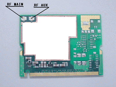
MU7FPCWL04
Dec 20, 2001Wireless LAN Device
Equipment Class
DSS - Part 15 Spread Spectrum Transmitter
MU7FPCWL02
Apr 02, 2001Spread Spectrum Transceiver
Equipment Class
DSS - Part 15 Spread Spectrum TransmitterMU7-2000
Jun 02, 1996Notebook Computer
Equipment Class
JBC - Part 15 Class B Computing Device/Personal ComputerMU7-7500
May 29, 1996Notebook Computer
Equipment Class
JBC - Part 15 Class B Computing Device/Personal ComputerMU71000
May 13, 1996Laptop Computer Maximum video resolution: 800 X 600
Equipment Class
JBC - Part 15 Class B Computing Device/Personal Computer