MUHMODULE1Thermostat Wireless Interface
Venstar Inc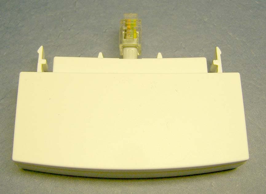
Click to zoom
Application Details
- Equipment Class
- DXX - Part 15 Low Power Communication Device Transmitter
- Date of Grant
- Apr 08, 2007
- Application Purpose
- Original Equipment
- Date of Application
- Apr 08, 2007
- Equipment Note
- Thermostat Wireless Interface
- Frequency Range
- 909.26900000 - 920.30800000
- Company
- Venstar Inc
- Country
- United States
Documents & Files
Document Text
Text extracted from the exhibit documents filed with the FCC. Open a document above to read the original.
Users Manual
Replacement Components Division Carrier Corporation 02/07 Complete Control from BASE STATION & RF WIRELESS MODULE BASE STATION & RF WIRELESS MODULE BASE STATION & RF WIRELESS MODULE BASE STATION & RF WIRELESS MODULE COMFORT CALL COMFORT CALL COMFORT CALL COMFORT CALL OWNER’S MANUAL OWNER’S MANUAL COMFORT CALL SYSTEM P/N P374-0433 COMFORT CALL SYSTEM P/N P374-0433 TOTALINE Compatible with thermostat models: P374-1700, P374-1800, P374-1900, P374-2700, P374-2800, & P374-2900 for a complete list contact RCD Overview Location of Controls, Indicators & Connections Table of Contents Installation & Setup Resetting the Access Code Operation Link up to 4 Thermostats to 1 Base Station Control of the Thermostat’s Auxiliary Output Menu of Touch Tone Keys Warranty Page 1 P/N P374-0433 Replacement Components Division Carrier Corporation 02/07 This device complies with Part 15 of the FCC Rules. Operation is subject to the following two conditions: (1) this device may not cause harmful interference, and (2) this device must accept any interference received, including interference that may cause undesired operation. C c F Comfort Call P374-0433 FCC ID MUHBASE1 FCC ID MUHMODULE1 Overview Page 2 Comfort Call allows you to call and ‘talk’ to your compatible thermostat. Monitoring and controlling your thermostat is now simple and easy from any phone, from anywhere. Comfort Call employs the latest in voice recognition and synthesis technology. It can tell you the indoor temperature of your home and the outdoor temperature, provided there is a working outdoor sensor connected to the thermostat. Once on the phone with your system, you may tell your thermostat to change to your preset Comfort Settings or go into your preset ‘unoccupied’, Energy Savings Settings (page 15). Comfort Call consists of two parts: A base station (page 6) that connects to the phone line and a RF Wireless Module that plugs into your compatible thermostat (page 5). Once Comfort Call answers, you will be prompted to enter a Security Access Code. This code is preset to 1111. You may change this code to any four digit number, if desired (page 13). Some homes may have more than one thermostat. If there is more than one thermostat, Comfort Call will have a menu option to access up to four different thermostats (page 16). As an added feature, some of our compatible thermostat models allow for the remote control of an auxiliary output on the thermostat. This auxiliary output may be accessed and controlled from Comfort Call as well (pages 17 and 18). An example of the use of this auxiliary output: The output is connected to a Powerflash Interface PF284 to turn on or off the indoor lighting wirelessly. Overview continued Page 3 Comfort Call requires an analog telephone line. If this system is installed at a primary residence, then the ring selector on the base station should be set to pick up the line after seven rings (page 10). With this setting, Comfort Call will not answer before an occupant is likely to pick up the phone. If an answering machine or fax machine is connected to Comfort Call, then the answering/fax machine should be set to pick up before Comfort Call (the ring selector is set to seven rings). In the case of a connected answering machine, after the tone to leave a message is heard, the user enters the Comfort Call security code. Comfort Call will release the answering machine from the line and control of the thermostat is now possible. In the case of a fax machine, after the ‘handshake’ tones are heard, there are moments of silence; during this silent period the Comfort Call security code should be entered. Comfort Call will release the fax machine from the line and control of the thermostat will be possible. Please note that some phone services provide a ‘voicemail’ answering service. These services release the home phone line after a preset number of rings and transfer the call to an internal voicemail system. Comfort Call is not compatible with this type of voicemail system. Comfort Call is a solution for people who do not have the same occupied patterns every day for their homes. It is also a convenient way to call ahead to make sure the primary or vacation home is comfortable upon arrival. At the thermostat, select the mode (Auto, Heat Cool, or Off). Adjust the setpoints to the desired settings. Here, at the base station, press the corresponding button for 5 seconds. The LED will flash for 5 minutes. Within 5 minutes of pressing the button on the base station, press the link button on the receiver for 3 seconds. The LED on the receiver will flash twice. The base station will now remember your settings. You may change these settings at anytime by repeating the above steps. Refer to owner’s manual for more details 1 1 4 4 77 RINGS 11 22 33 44 9vac Power LINE Power and Link LED Indicator Comfort Settings Link Button Ring Selector Switch Link Button Link LED Indicator Energy Savings Link Button Location of Controls, Indicators & Connections Page 4 ANSWER MACH., FAX, OR PHONE ANSWER MACH., FAX, OR PHONE COMFORT CALL 9vac Power LINE energy comfort FAN OUTSIDE HUMIDITY PROGRAM VACATION SET CLOCK MODE Premier Residential Programmable Thermostat Connect the RF Wireless Module to the thermostat as shown below. Installation & Setup Page 5 Accessory release button Accessory jack located on bottom of thermostat RF Wireless Module To remove the RF Wireless Module from the thermostat, press and hold the accessory release button while removing the RF Wireless Module from the thermostat’s accessory jack. To connect the RF Wireless Module to the thermostat, insert the RF Wireless Module plug into the accessory jack of the thermostat. The RF Wireless Module has two tabs that fit into the ventilation slots of the thermostat for added stability. PROGRAM VACATION SET CLOCK MODE HUMIDITY OUTSIDE FAN Premier Residential Programmable Thermostat Installation & Setup Page 6 Connect the telephone line to the Base Station and power Comfort Call with the …
Text truncated - open the document above for the full version.
Cover Letter(s)
Zubiel RF Systems, Inc. 17335 Colonial Park Drive • Monument, CO 80132 Tel: (719) 488-8535 • Fax: (719) 488-8546 • e-mail: [email protected] Web: http://www.zubiel.com CAGE: 0NG36 DUNS: 62-088-9980 February 2, 2007 To: Federal Communications Commission 7435 Oakland Mills Road Columbia, MD 21046-1609 Curtis-Straus LLC TCB 527 Great Rd Littleton, MA 02702 Confidentiality Request FCC ID: MUHMODULE1 Authorization and Evaluation Division Pursuant to Sections 0.457 and 0.459 of the Commission's Rules, the applicant hereby requests confidential treatment of information accompanying this application as outlined below: Schematics Block Diagram Operational Description The above materials contain trade secrets and proprietary information not customarily released to the public. The public disclosure of these matters right be harmful to the applicant and provide unjustified benefits to its competitors. Sincerely, Stanley T. Zubiel, President
External Photos
WIRELESS MODULE - EXTERNAL FRONT VIEW WIRELESS MODULE - EXTERNAL REAR VIEW
ID Label/Location Info
The FCC ID for the RF Wireless Module is: MUHMODULE1 2 . 8 9 " 1.53" FCC ID: MUHMODULE1 1 . 5 " .25" The label and location on the unit is shown below. The required FCC statement is included in the Owner's Manual. Venstar Inc.
Internal Photos
WIRELESS MODULE - INTERNAL FRONT VIEW WIRELESS MODULE - INTERNAL REAR VIEW
Contact Information
Applicant
Corey McTigue(Engineering Manager)
Test Firm
Criterion Technology Corp.Lou Schornack
Technical Specifications
| # | Rule Parts | Frequency Range | Power Output |
|---|---|---|---|
| 1 | 15C | 909.269 MHz - 920.308 MHz | - |
Other Applications from Venstar Inc

MUH-EMSQ25
Feb 05, 2026WiFi Thermostat
Equipment Class
DTS - Digital Transmission SystemMUH-EMSQ22
Jan 18, 2024WiFi Thermostat
Equipment Class
DTS - Digital Transmission System
MUH-SQNSQ22
Jul 27, 2023Thermostat with WiFi capabilities
Equipment Class
DTS - Digital Transmission System
MUH-SURVEYOR1
Mar 24, 2022Data Concentrator
Equipment Class
DTS - Digital Transmission System
MUH-SKYPORT14
Jan 31, 2021Thermostat with WiFi, BLE, Subgig
Equipment Class
DTS - Digital Transmission System