MX5-S820ICard Printer with RFID and Laminator
Eltron Products
Click to zoom
Application Details
- Equipment Class
- DXX - Part 15 Low Power Communication Device Transmitter
- Date of Grant
- May 05, 2003
- Application Purpose
- Original Equipment
- Date of Application
- May 05, 2003
- Equipment Note
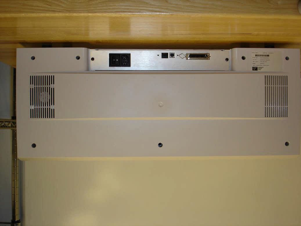
- Card Printer with RFID and Laminator
- Frequency Range
- 13.56000000 - 13.56000000
- Company
- Eltron Products
- Country
- United States
Documents & Files
Document Text
Text extracted from the exhibit documents filed with the FCC. Open a document above to read the original.
Users Manual
3M MAXSecure Printer Module Maintenance Manual Manual No. 980286-001Rev. A FOREWORD This manual contains service and repair information for 3M MAXSecure Printer Modules manufactured by the 3M Corporation,St. Paul, Minnesota. The contents include maintenance, diagnosis and repair information. TECHNICAL SUPPORT For technical support, users should first contact the distributor that originally sold the product—phone +1 (800) 344 4003 to locate the nearest 3M Distributor. COPYRIGHT NOTICE This document contains information proprietary to 3M Corporation. This document and the information contained within is copyright by 3M Corporation and may not be duplicated in full or in part by any person without prior written approval of 3M.. While every effort has been made to keep the information contained within current and accurate as of the date of publication, no guarantee is given or implied that the document is error-free or that it is accurate with regard to any specification. This information is not intended as a license to practice or infringe on the patents of this company or others. 3M Corporation reserves the right to modify, update or revise this information at any time without notice. TRADEMARKS 3M MAXSecure is a service mark, and 3M is a registered trademark of 3M Corporation. All other marks are trademarks or registered trademarks of their respective holders. FCC NOTICE: This equipment has been tested and found to comply with the limits of a Class A digital device, pursuant to Part 15 of the FCC Rules. These limits are designed to provide reasonable protection against harmful interference when the equipment is operated in a commercial environment. This equipment generates, uses and can radiate radio frequency energy and, if not installed and used in accordance with the instructions, may cause harmful interference to radio communications. However, there is no guarantee that interference will not occur in a particular installation. Operation of this equipment in a residential area is likely to cause harmful interference in which case the user will be required to correct the interference at their own expense. CSA NOTICE: This equipment does not exceed Class A limits per radio noise emissions for digital apparatus set out in the Radio Interference Regulation of the Canadian Department of Communications. Operation in a residential area may cause unacceptable interference to radio and TV reception requiring the owner or operator to take whatever steps are necessary to correct the interference. Ce matériel ne dépasse pas les limites de Classe A d’émission de bruits radioélectriques pour les appareils numériques telles qu’établies par le ministère des Communications du Canada. L’exploitation faite en milieu résidentiel peut entraîner le brouillage des réceptions radio et télé, ce qui obligerait le propriétaire ou l’opérateur à prendre les dispositions nécessaires pour en éliminer les causes. i ii iii TABLE OF CONTENTS CHAPTER 1 GENERAL DESCRIPTION 1.1 PRINTER MODULE DESCRIPTION..................1-1 1.1.1 Clear Card Material Feed, Shear, and Flip-Over··············1-3 1.1.2 Print Station·······························1-3 1.1.3 White Card Feeder Station························1-4 1.1.4 Card Assembler Station··························1-5 1.2 OPTIONS AND ACCESSORIES....................1-5 1.3ABOUTTHISMANUAL........................1-5 1.4 CAUTIONARY NOTES.........................1-6 1.5 PACKAGING CONSIDERATIONS...................1-9 1.6 PREPARING A STATIC-SAFE WORK AREA...............1-9 1.7 ENVIRONMENTAL AND SHOCK PROTECTION . . .........1-9 CHAPTER 2 INSTALLATION AND OPERATION 2.1 INSTALLATION............................2-2 2.1.1 Unpacking································2-2 2.1.2 Location Concerns····························2-3 2.1.3 Adding the Laminator and Die Cutter···················2-3 2.1.4 Attaching Cables·····························2-4 2.1.5 Cable Diagrams·····························2-5 2.2 OPERATION..............................2-6 2.2.1 Controls and Indicators··························2-6 2.2.2 LCD Messages Related to Printer Module·················2-7 2.2.3 LCD Messages Related to Laminator Module···············2-7 2.2.4 LCD Messages Related to Encoder Module················2-8 2.2.5 LCD Messages Related to Adjustments, Testing, and Microcode Downloads 2-8 2.2.6 LCD Messages Related to Cleaning····················2-8 2.2.7 Print Head Latch and Release Levers···················2-9 2.2.8 Ribbon Installation···························2-10 2.2.9 Card Media·······························2-11 2.2.10 Clear Card Material Loads·······················2-11 2.2.11 White Card Feeder Loading······················2-12 2.2.12 Two- verses Three-Layer Selection···················2-13 CHAPTER 3 THEORY OF OPERATION 3.1 COLOR FUNDAMENTALS......................3-1 3.2 PRINTER INTRODUCTION......................3-5 3.3 CIRCUITRY..............................3-8 iv CHAPTER 4 TROUBLESHOOTING 4.1 DIAGNOSING BASIC PRINTER PROBLEMS..............4-2 4.2 DIAGNOSING COMPUTER INTERFACE PROBLEMS.........4-5 CHAPTER 5 REPLACEMENT PROCEDURES 5.1 REQUIRED TOOLS..........................5-2 5.2 PART REPLACEMENTS........................5-3 5.2.1 Case Removal······························5-3 5.2.2 White Card Feeder Station Removal···················5-4 5.2.3 White Card Feeder Station Replacements·················5-5 5.2.4 Upper Clear Card Station Removal····················5-6 5.2.5 Upper Clear Card Station Component Replacements···········5-7 5.2.6 Lower Clear Card Station Removal····················5-8 5.2.7 Lower Clear Card Station Components··················5-9 5.2.8 Card Assembly Station Removal·····················5-10 5.2.9 Card Assembly Station Component Replacements············5-11 5.2.10 Print Head Replacement························5-12 5.2.11 Fan Replacement···························5-17 5.2.12 Ribbon Sensor Replacement······················5-18 5.2.13 Cleaning Roller Spring Clip Replacement················5-19…
Text truncated - open the document above for the full version.
Users Manual
5.1REQUIRED TOOLS 3M Products recommends the following tools as potential additions to those on hand at a repair facility. These items outfit the facility for the maintenance and repair of 3M Max Secure Printer Modules: TOOL KIT Item No.Description 1 25 inch-pound Torque Screwdriver 2 15 inch-pound Torque Screwdriver 3 9 inch-pound Torque Screwdriver 4 5.5 inch-pound Torque Screwdriver 5 4 inch-pound Torque Screwdriver 6 2.5 inch-pound Torque Screwdriver 7 3mm Hex Bit—1/4-inch Drive 8 1.5mm Allen Bit—1/4-inch Drive 9 13mm Socket 10 5mm Socket 11 5.5-Millimeter Open End Wrench 12 Number 1 Phillips Bit 13 Number 2 Phillips Bit 14 Number 2 Slot Bit Screwdriver 15 Snap Ring Pliers 16 13mm E-Ring Tool 17 8.5mm E-Ring Tool 18 Wire Cutters (Small) 19 Spring Hook 20 Shim Gage, 0.030-inch (Eltron 900223-001) 21 Shim Gage, 0.010-inch (Eltron 900222-001) 22 Clutch Torque Fixture—FX540 23 Clutch Gage (Eltron C413) 24 Shim Fixture (Eltron 900400-203 15 Shim Gage (Eltron 900400-201) 26 Shim Gage (Eltron 900412-001) 27 Pulley Press Fixture (Eltron 900103-002) 28 Spacing Gage, Gear (Eltron 900224-001) 29 Stepper Belt Tensioning Fixture (Eltron 900116-001) 30 Left Front Belt Tensioning Fixture (Eltron C601) 31 Right Front Belt Tensioning Fixture (Eltron C599) 5-2980286-001 Rev. A CHAPTER 5 REPLACEMENT PROCEDURES 5.2PART REPLACEMENTS The following sections describe the requirements for removing both major assemblies and, where applicable, components on those assemblies that appear in the list of spares. Only removal descriptions appear. Unless noted otherwise, replacements can take place by reversing the steps required for removals. Also, replacements for some items in the spares list do not appear. These items are considered too easily identifiable to warrant descriptions. 5.2.1Case Removal Figure 5-1 shows the fasteners holding the case members. Four case parts exist—the hinged front panel, two side panels, and the back panel, which includes the top and hinged front cover. Note that the four fasteners holding the back panel only require loosening. Service personnel can then separate this case member by lifting it straight up. Most of the procedures that follow require the removal of one or more case members. 980286-001 Rev. A5-3 CHAPTER 5 REPLACEMENT PROCEDURES Figure 5-1. Case Fasteners. 5.2.2White Card Feeder Station Removal Refer to Figure 5-2, and proceed as follows Step 1.Swing down the Front Panel and remove the, Rear, and Right Side Panels (see Section 5.2.1). Step 2.To replace the complete unit, unplug J3, J5 and the upper part of J17 on the Extension Board, and cut all related cable ties leading to the White Card Feeder Station. Step 3.Remove the four screws holding the unit to the Rear Plate. Step 4,To replace the unit, separate the unit from the Printer Module while feeding the cables through the rear plate access cutout. To replace the timing belt or related dc motor, position the unit on one side while taking care to avoid stressing the cable wires. Then continue with the following section. 5-4 980286-001 Rev. A CHAPTER 5 REPLACEMENT PROCEDURES Figure 5-2. White Card Feed Station Removal. 5.2.3White Card Feeder Station Replacements Figure 5-3 shows the White Card Feeder Station. The timing belt, associated drive motor, and rollers are considered replaceable. After replacing the timing belt, adjust belt tension as follows: Step 1.Loosen the two screws holding the Idler Pulley bracket. Step 2.Swing the Idler Pulley against the timing belt to remove slack in the belt. Only remove belt slack. Do not stretch the belt. Step 3.While holding the bracket in the position established in step 2, tighten the two screws. 980286-001 Rev. A5-5 CHAPTER 5 REPLACEMENT PROCEDURES Figure 5-3. White Card Feeder Components. 5.2.4Upper Clear Card Station Removal Figure 5-4 shows the fasteners holding the Upper Clear Card Station, the connections on the Expansion board, and the timing belt that extends card drive to the lower unit. To remove the unit, proceed as follows: Step 1.Remove the rear and right side case parts (see Section 5.3.1) and the Card Feeder Assembly (see Section 5.2.2). Step 2.Unplug the Shear, Stepper, and Clear Material Sensor connectors. Cut associated cable ties. Step 3.Remove the timing belt that couples rollers in the Upper and Lower Clear Card Stations and the two fasteners holding the Upper Clear Card Station. The idler pulley can fall off, so take care not to loose it. Step 4.While feeding the cables through the access cut outs in the rear plate, remove the Upper Clear Card Station. 5-6 980286-001 Rev. A CHAPTER 5 REPLACEMENT PROCEDURES Figure 5-4. Upper Clear Card Station Removal. 5.2.5Upper Clear Card Station Component Replacements The Upper Clear Card Station includes a stepper motor, a related timing belt (that extends card drive to the lower unit), a Clear Material sensor, and the Clear Card Shear. Service personnel can replace any of these components and the Card Feed roller. The Clear Card Shear has a useful life in excess of 100,000 cuts. Figure 5-5 shows the fasteners for these components. 980286-001 Rev. A5-7 CHAPTER 5 REPLACEMENT PROCEDURES Figure 5-5. Upper Clear Card Station Replaceable Components. 5.2.6Lower Clear Card Station Removal Refer to Figure 5-6, and proceed as follows: Step 1.Remove the Upper Clear Card Station (see Section 5.2.4). Step 2.Remove White Card Feeder Station sufficiently to gain clearance from the Lower Clear Card Station (see Section 5.2.2). Step 3.Remove connectors on the Clear Card Controller board that connect to the Lower Clear Card Station and J17 on the CPU Extension board (see Figure 5-26). Step 4.Remove the fasteners holding the Clear Card Controller board, and swing the board away from the underlying Lower Clear Card Station fasteners. Step 5.Remove the fasteners holding the Lower Clear Card Station, both front and back. Then, while feeding the cables through the cutouts in the Rear Plate, lift the unit away from the Printer module. 5-8 98028…
Text truncated - open the document above for the full version.
Block Diagram
16/12/02 REV:1 Company Confidential –P310_420USA.doc Page 2 of 3 1- Hardware description The S820i CPU board is organize as following : DC Motor advance ribbon, feeder, move head (up/down) Sensor & measure including E2pot to allow self adjustment (no potentiometer) card sensor, Ribbon rotation, color sensor, Head temperature, Power supply, head position (up/down) cover open, Press button MEMORY FLASH MEMORY Base : 512K bytes DRAM : 4M bytes Flipover PCBA connection Stepper motor Print head management Clock 14.56 MHz Communication serial port : (Tx, Rx) 9600 to 115200 baud Parallel port : standard Centronic μP LCD PCBA RFID PCBA connection RF Clock 13.56 MHz Processor Clock 10 MHz Printer Extension PCBA connection Laminator Station (S820) Processor Clock 32 MHz
Cover Letter(s)
1001 Flynn Road Camarillo, CA 91360 l Page 1 Company Confidential To: Ruby Hall Compatible Electronics, Inc 2337 Troutdale Dr. Agoura, CA 91301 From: Danny Louie, Card Printer Engineering Manager Date: 4/21/03 Re: Confidentiality of S820i Card Printer Schematics Ruby, In accordance with section 47 CFR 0.457(d) of the FCC Rules, all electronic schematics provided for the S820i FCC agency approval must be held in confidentiality. These schematics are proprietary to Zebra/Eltron Card Printer Products and reveal the RFID (Radio Frequency IDentification) circuit design that allows the S820i card printer to have a technical advantage and unique market feature for which we have applied a patent application to protect this design. This RFID PCBA circuit design works in conjunction through radio frequency at 13.56Mhz with our patented color ribbon (embedded with a Philipps RFID transponder that stores data related to ribbon type, ribbon count, ribbon OEM code) to be accurately detected in the S820i card printer and configured correctly by the printer’s electronics and windows driver to automatically set the correct ribbon, which eliminates the need for the user to manually enter these settings. This design also eliminates the possibility of users’ error to install the wrong color ribbon and provides a constant, up-to-date ribbon count and feedback stored on the ribbon back to the user for information. Please consider this letter a request for non-disclosure submitted pursuant to 47 CFR 0.459. Sincerely, Danny Louie Zebra/Eltron Card Printer Products 1001 Flynn Road Camarillo, CA 93012
Operational Description
1001 Flynn Road Camarillo, CA 93012.8706 U.S.A. Telephone +1.805.578.0000 Facsimile +1.805.581.0000 www.eltroncards.com Ruby Hall Compatible Electronics, Inc 2337 Troutdale Dr. Agoura, CA 91301 Ruby, The functionality of the RFID portion of the S820 printer is a read/write process to an encoded ribbon. The RFID will identify the ribbon and will count and update the available number of prints remaining on the ribbon. If the RFID does not see the proper encoded ribbon the printer will disable printing operations. Sincerely, Randy Tan Eltron Card Printer Products 1001 Flynn Road Camarillo, CA 93012
Test Report
FCC ID: MX5-S820I Report Number: A21003F1 2337 TROUTDALE DRIVE, AGOURA, CALIFORNIA, 91301 • PH: (818) 597-0600 FX: (818) 597-1187 Page 1 of 17 FCC PART 15, SUBPART C TEST REPORT for CARD PRINTER Model: S820i with RFID AND LAMINATOR FCC ID: MX5-S820I Prepared for ZEBRA TECHNOLOGIES CORP. 1001 FLYNN RD CAMARILLO, CA 93012 Prepared by:_____________________ ANDRE D. KHAN Approved by:____________________ RUBY A. HALL COMPATIBLE ELECTRONICS INC. 2337 TROUTDALE DRIVE AGOURA, CALIFORNIA 91301 (818) 597-0600 DATE: OCTOBER 18, 2002 REPORTAPPENDICESTOTAL BODYABCDE PAGES 17 2 2 2 11 12 46 This report shall not be reproduced except in full, without the written approval of Compatible Electronics. FCC ID: MX5-S820I Report Number: A21003F1 2337 TROUTDALE DRIVE, AGOURA, CALIFORNIA, 91301 • PH: (818) 597-0600 FX: (818) 597-1187 Page 2 of 17 TABLE OF CONTENTS Section / TitlePAGE GENERAL REPORT SUMMARY4 SUMMARY OF TEST RESULTS4 1. PURPOSE5 2. ADMINISTRATIVE DATA6 2.1 Location of Testing6 2.2 Traceability Statement6 2.3 Cognizant Personnel6 2.4 Date Test Sample was Received6 2.5 Disposition of the Test Sample6 2.6 Abbreviations and Acronyms6 3. APPLICABLE DOCUMENTS7 4. Description of Test Configuration8 4.1 Description of Test Configuration - EMI8 4.1.1Photograph of Test Configuration – EMI8 4.1.2 Cable Construction and Termination9 5. LISTS OF EUT, ACCESSORIES AND TEST EQUIPMENT10 5.1 EUT and Accessory List10 5.2 EMI Test Equipment11 6. TEST SITE DESCRIPTION12 6.1 Test Facility Description12 6.2 EUT Mounting, Bonding and Grounding12 7. Test Procedures13 7.1 RF Emissions13 7.1.1 Conducted Emissions Test13 7.1.2 Radiated Emissions Test14 7.1.3RF Emissions Test Results15 7.1.4 Sample Calculations16 8. CONCLUSIONS17 FCC ID: MX5-S820I Report Number: A21003F1 2337 TROUTDALE DRIVE, AGOURA, CALIFORNIA, 91301 • PH: (818) 597-0600 FX: (818) 597-1187 Page 3 of 17 LIST OF APPENDICES APPENDIXTITLE ALaboratory Accreditations BModifications to the EUT CAdditional Models Covered Under This Report DDiagrams, Charts and Photos • Test Setup Diagrams • Antenna and Amplifier Gain Factors • Radiated and Conducted Emissions Photos EData Sheets LIST OF FIGURES FIGURETITLE 1 Conducted Test Setup 2 Plot Map And Layout of Test Site FCC ID: MX5-S820I Report Number: A21003F1 2337 TROUTDALE DRIVE, AGOURA, CALIFORNIA, 91301 • PH: (818) 597-0600 FX: (818) 597-1187 Page 4 of 17 GENERAL REPORT SUMMARY This electromagnetic emission report is generated by Compatible Electronics Inc., which is an independent testing and consulting firm. The test report is based on testing performed by Compatible Electronics personnel according to the measurement procedures described in the test specifications given below and in the "Test Procedures" section of this report. The measurement data and conclusions appearing herein relate only to the sample tested and this report may not be reproduced in any form except in full, without the written permission of Compatible Electronics. This report must not be used to claim product endorsement by NVLAP or any other agency of the U.S. Government. Device Tested:Card Printer Model: S820i S/N: None Product Description:This is a Card Printer with Laminator. Modifications:The EUT was not modified during the testing. Manufacturer:Zebra Technologies, Corp. 1001 Flynn Rd. Camarillo, CA 93012 Test Date:October 03, 2002 Test Specifications:EMI requirements FCC CFR Title 47, Part 15 Subpart C Test Procedure: ANSI C63.4: 2000. Test Deviations:The test procedure was not deviated from during the testing. SUMMARY OF TEST RESULTS TESTDESCRIPTIONRESULTS 1Radiated RF Emissions, 10kHz to 1.0GHz Complies with the limits of FCC CFR Title 47, Part 15 Subpart C 15.209 and 15.225. 2Conducted Rf Emissions,450 kHz – 30 MHzComplies with the limits of FCC CFR Title 47, Part 15 Subpart C 15.207 (a). FCC ID: MX5-S820I Report Number: A21003F1 2337 TROUTDALE DRIVE, AGOURA, CALIFORNIA, 91301 • PH: (818) 597-0600 FX: (818) 597-1187 Page 5 of 17 1.PURPOSE This document is a qualification test report based on the Electromagnetic Interference (EMI) tests performed on the Card Printer Model: S820i. The EMI measurements were performed according to the measurement procedure described in ANSI C63.4: 2000. The tests were performed in order to determine whether the electromagnetic emissions from the equipment under test, referred to as EUT hereafter, are within the specification limits defined in FCC CFR Title 47, Subpart C 15.207 (a), 15.209 and 15.225. FCC ID: MX5-S820I Report Number: A21003F1 2337 TROUTDALE DRIVE, AGOURA, CALIFORNIA, 91301 • PH: (818) 597-0600 FX: (818) 597-1187 Page 6 of 17 2.ADMINISTRATIVE DATA 2.1Location of Testing The EMI tests described herein were performed at the test facility of Compatible Electronics, 2337 Troutdale Drive, Agoura, California 91301. The temperature cycle testing was performed at Environment Associates, Inc. 9604 Variel Ave. Chatsworth, CA 91311. 2.2Traceability Statement The calibration certificates of all test equipment used during the test are on file at the location of the test. The calibration is traceable to the National Institute of Standards and Technology (NIST). 2.3Cognizant Personnel Zebra Technologies, Corp. Zaven MangassarianCompliance Engineer Compatible Electronics Inc. Andre D. KhanTest Technician Ruby A. HallLab Manager 2.4Date Test Sample was Received The test sample was received on October 03, 2002. 2.5Disposition of the Test Sample The test sample remains at Compatible Electronics, Inc. 2.6Abbreviations and Acronyms The following abbreviations and acronyms may be used in this document. RFRadio Frequency EMIElectromagnetic Interference EUTEquipment Under Test P/NPart Number S/NSerial Number HPHewlett Packard ITEInformation Technology Equipment CMLCorrected Meter Limit LISNLine Impedance Stabilization Network FCC ID: MX5-S820I Report Number: A21003F1 2337 TROUTDALE DRIVE, AGOURA, CALIFORNIA, 91301 • PH: (818) 597-0600 FX: (818) 597-1187 Page 7 of 17 3.APPLICABLE DOCUMENTS The following documents ar…
Text truncated - open the document above for the full version.
Contact Information
Applicant
Zaven Mangassarian(Compliance Engineer)
Technical Contact
Compatible ElectronicsJoey J Madlangbayan
[email protected]818-597-0600
2337 Troutdale Drive · Agoura, California · United States
Test Firm
Compatible ElectronicsRuby Hall
Technical Specifications
| # | Rule Parts | Frequency Range | Power Output | Tolerance |
|---|---|---|---|---|
| 1 | 15C | 13.56 MHz - 13.56 MHz | - | 0.0100000000 % |
Other Applications from Eltron Products
MX5-P640I
Jun 01, 2005Radio frequency identifier
Equipment Class
DXX - Part 15 Low Power Communication Device Transmitter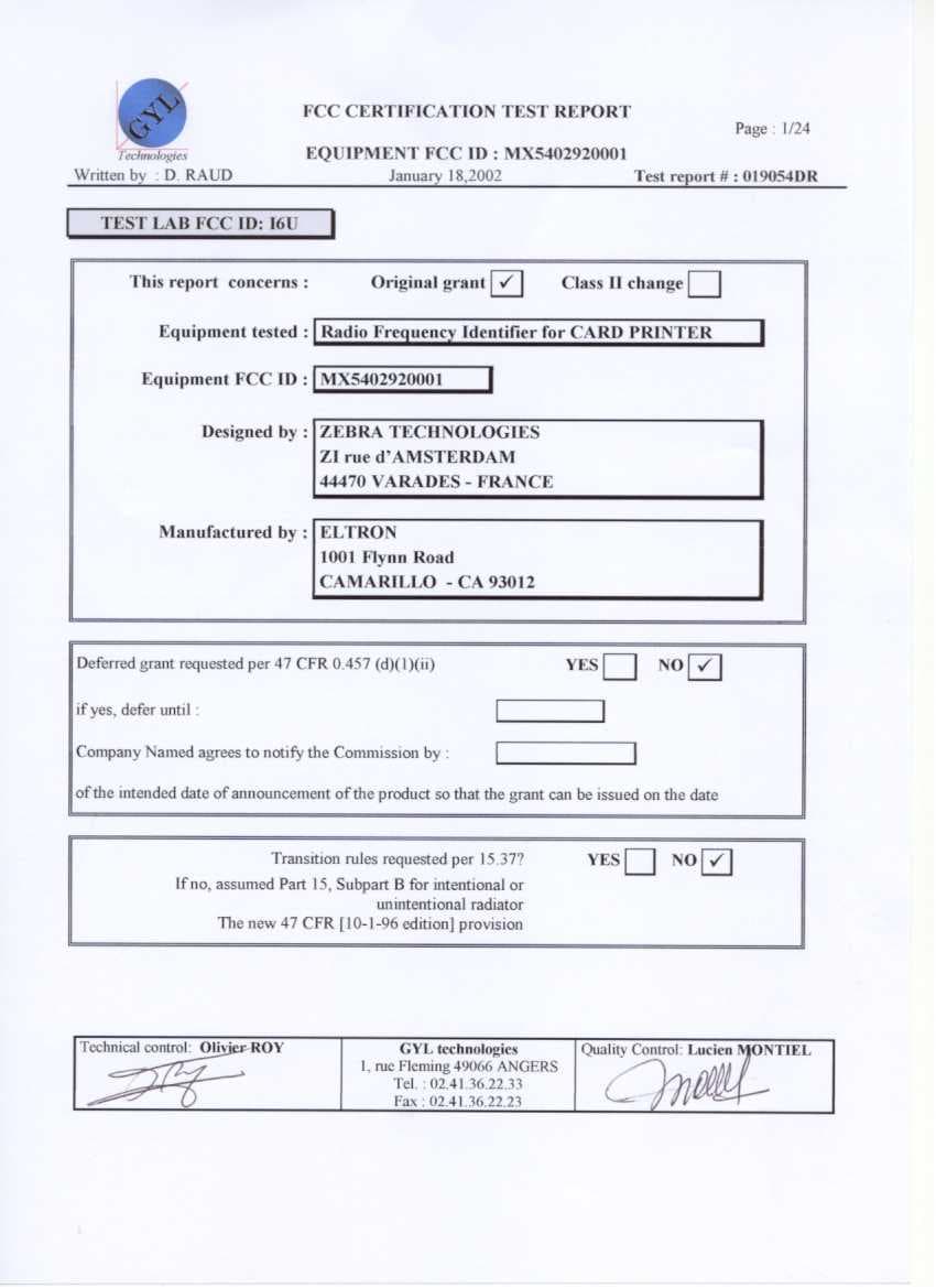
MX5402920001
Apr 04, 2002Radio Frequency Identifier
Equipment Class
DXT - Part 15 Low Power Transceiver, Rx Verified
MX5-P2222
Nov 08, 1999DXX - Part 15 Low Power Communication Device Transmitter
Equipment Class
DXX - Part 15 Low Power Communication Device TransmitterMX521631
Sep 16, 1996JBP - Part 15 Class B Computing Device Peripheral
Equipment Class
JBP - Part 15 Class B Computing Device PeripheralMX5-TIGER
May 28, 1996Label Printer
Equipment Class
JBP - Part 15 Class B Computing Device Peripheral