MX5402920001Radio Frequency Identifier
Eltron Products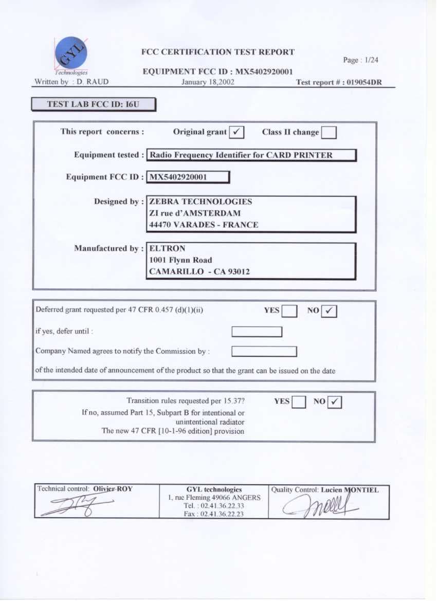
Click to zoom
Application Details
- Equipment Class
- DXT - Part 15 Low Power Transceiver, Rx Verified
- Date of Grant
- Apr 04, 2002
- Application Purpose
- Original Equipment
- Date of Application
- Feb 03, 2002
- Equipment Note
- Radio Frequency Identifier
- Frequency Range
- 13.56000000 - 13.56000000
- Company
- Eltron Products
- Country
- United States
Documents & Files
Document Text
Text extracted from the exhibit documents filed with the FCC. Open a document above to read the original.
Users Manual
1 Part Number: 980363-001Rev.A © Zebra Technologies Corporation Welcome to your new Eltron P205 (Monochrome) & Eltron P210 (Color) User’s Manual 2 FOREWORD This manual contains installation and operation information for the Eltron P200 Series card printers manufactured by Zebra Technologies Corporation. RETURN MATERIALS AUTHORIZATION Before returning any equipment to Zebra Technologies Corporation for in-warranty or out-of-warranty repair, contact Repair Administration for a Return Materials Authorization (RMA) number. Repack the equipment in the original pac- king material and mark the RMA number clearly on the outside. Ship the equipment, freight prepaid, to the address listed below: For USA and Latin America: Zebra Technologies Corporation Eltron Card Printer Products 1001 Flynn Road Camarillo, CA. 93012-8706.USA Phone: +1 (805) 579-1800 FAX: +1 (805) 579-1808 For Europe, Asia and Pacific: Zebra Technologies Inc. France Eltron Card Printer Products Zone Industrielle, Rue d’Amsterdam 44370 Varades, France Phone: + 33 (0) 240 097 070 FAX: + 33 (0) 240 834 745 COPYRIGHT NOTICE This document contains information proprietary to Zebra Technologies Corporation. This document and the information contained within is Copyrighted by Zebra Technologies Corporation and may not be duplicated in full or in part by any person without written approval from Zebra. While every effort has been made to keep the information contained within current and accurate as of the date of publication, no guarantee is given that the document is error-free or that it is accurate with regard to any specification. Zebra reserves the right to make changes, for the purpose of product improvement, at any time. TRADEMARKS Eltron is a registered trademark of Zebra Technologies Corporation. Windows and MS.DOS are registered trademarks of Microsoft Corp. All other trademarks or registered trademarks are marks of their respective holders. 4 DECLARATIONS OF CONFORMITY This equipment has been tested and found to comply with the limits for a Class B digital device, pursuant to part 15 of the FCC Rules. These limits are designed to provide reasonable protection against harmful interference in a residential installation. This equipment generates, uses ans can radiate radio frequency energy and, if not installed and used in accordance with the instructions, may cause harmful interference to radio communications. However, there is no guarantee that interference will not occur in a particular installation. If this equipment does cause harmful interference to radio or television reception, which can be determined by turning the equipment off and on, the user is encouraged to try to correct the interference’s by one or more of the following measures: Reorient or relocate the receiving antenna. Increase the separation between the equipment and the receiver. Connect the equipment into an outlet on a circuit different from that to which the receiver is connected. Consult the dealer or an experienced radio/TV technician for help. The user may find the following booklet, prepared by the FederalCommunications Commission, helpful: How to identify and resolve Radio/TV Interference Problems. This booklet is available from the U.S. Government printing Office, Washington, D.C. 20402, Stock No. 004-000-00345-4. Use of a shielded cable is required to comply within Class B limits of Part 15 of FCC Rules. Pursuant to Part 15.21 of the FCC Rules, any changes or modifications to this equipment not expressly approved by Eltron may cause, harmful interference and void the FCC authorization to operate this equipment. 73/23/EEC modified by 93/68/EEC EMC Directive EN 500082-1,1992 Immunity to Electromagnetic Disturbances European Council Directive Compliance to Standards 89/336/EEC modified by 92/31/EEC and 93/68/EEC RF Emissions control Low voltage Directive EMC Directive EN 60950 EN 55022-A Product safety Model: P210conforms to the following specification: FCC Part 15, Subpart A, Section 15.107(a) and Section 15.109(a) Class B digital device 5 INTRODUCTION Thank you for choosing the Eltron P210 Plastic Card Printer. Eltron’s P200 series card printers offer a low cost, high quality solution to those requiring computer-controlled printing and encoding of credit card style plastic cards. Card applications include customer loyalty, access control, visitor, membership, gift cards, durable business cards. This manual guides you to efficient start up and operation of your new Card Printer. P210/P205 PRINTER MODELS The Eltron Product Number tells a story: Here is a quick review of the Eltron Card Printer Series numbering and lettering system to help you. The P210 Plastic Card Printer employs Dye Sublimation and Resin Thermal Transfer technologies. Model numbers include identifiers that specify options using the following lettering conventions: Smart Card: O = No Magnetic Encoder: O = No M = Yes Magnetic Encoder Options: O = No 1 = Stripe down HICO 2 = Stripe Down LOCO 3 = Stripe Up HICO 4 = Stripe Up LOCO Memory: O = Standard Interface: U= USB / Parallel R= USB / Serial } Ship-away kit P210C - 0 X X 0 X - X D Windows Drivers & User Documentation CD: D= Drivers & Documentation Power Cord: O = None A = 120 VAC E = 220 VAC U = UK 7 1 2 3 4 5 TABLE OF CONTENTS GETTING STARTED • • • • • • • • • • • • • • • • • • • • •9 1 • 1 Unpacking your P210 • • • • • • • • • • • • • • • • • • • • • • • • • • • • • • • • • • • • • • • • • • • • • • • •9 1 • 2 Indicators and control • • • • • • • • • • • • • • • • • • • • • • • • • • • • • • • • • • • • • • • • • • • • • • •11 1•3 Printer installation • • • • • • • • • • • • • • • • • • • • • • • • • • • • • • • • • • • • • • • • • • • • • • • • • •12 OPERATION • • • • • • • • • • • • • • • • • • • • • • • • •13 2 • 1 Printer Features • • • • • • • • • • • • • • • • • • • • • • • • • • • • • • • • • • • • • • • • • • • • • • • • • • •13 2 • 2 Loading ribbon cartridge • • • • • • • • • • • • • • • • • • • • • • • • • • • • • • • • • • …
Text truncated - open the document above for the full version.
Block Diagram
ZEBRA TECHNOLOGIES France – ZI, rue d’Amsterdam – 44370 VARADES – France RFID BLOCK DIAGRAM Printing Ribbon Frame MICRO CONTROLLER POWER SUPPLY +5V RF MANAGEMENT RF ANTENNA OSCILLATOR OSCILLATOR EEPROM RF ANTENNA TRANSPONDER ZEBRA TECHNOLOGIES France – ZI, rue d’Amsterdam – 44370 VARADES – France LOCATION OF RFID IN A P210 PRINTER MODEL MICRO CONTROLLER DC MOTOR (ribbon, feeder, print head) STEPPER MOTOR (card) MEMORY (Flash, RAM) PORTS (USB, Parallel, RS232) MAGNETIC ENCODER (Hico, Loco) SWITCH + LEDs // to serial printing data PRINT HEAD SMART I/O Smart Signal SENSORS (feeder, synchro card, magnetic, color) SWITCH HEAD LOCK FAN MOTOR EXTERNAL POWER SUPPLY 24V POWER SUPPLIES (+5V, +12V, +24V) RFID BOARD ZEBRA TECHNOLOGIES France – ZI, rue d’Amsterdam – 44370 VARADES – France LOCATION OF RFID IN A P310 PRINTER MODEL MICRO CONTROLLER DC MOTOR ( ribbon, feeder, p rint head ) STEPPER MOTOR ( card ) MEMORY ( Flash , DRAM ) PORTS (USB, Parallel, RS232) MAGNETIC ENCODER (Hico, Loco) LCD + LEDs PRINT HEAD MANAGEMENT SMART SENSORS (feeder, synchro card, magnetic, color, cover open) FAN MOTOR EXTERNAL POWER SUPPLY 24V POWER SUPPLIES (+5V, +12V, +24V) RFID BOARD FLIP OVER ( usin g I²C ) EXTERNALCONNECTOR(for ext-ended I/O,extended memor y) ZEBRA TECHNOLOGIES France – ZI, rue d’Amsterdam – 44370 VARADES – France RFID FUNCTION DESCRIPTION : When the printing ribbon frame is inserted into the printer, the RFID board functioning at 13,56MHz, send, through the RF antenna, a signal to the transponder in order to power it, this allows the transponder to send back to the board the rec ognition signal. During operation the two features are communicating each other. The goal of this feature is to recognize the ribbon typ e as well as the ribbon counter to know the quantity of remaining panels. RFID BOARD RF ANTENNA embedded into the board TRANSPONDER distance maximum 2 cm Antenna Ribbon frame
External Photos
Technologies GY L G Y L FCC CERTIFICATION TEST REPORT EQUIPMENT FCC ID : MX5402920001 Page : 2/25 Written by : D. RAUDJanuary 18,2002Test report # : 019054DR TABLE OF CONTENTS Page 1E.U.T TECHNICAL DESCRIPTION _________________________________________ 4 1.1 Product description ____________________________________________________________4 1.2 List of EMI critical components __________________________________________________4 1.3 Tested systems details___________________________________________________________4 1.4 Test Methodology and procedure _________________________________________________5 1.5 Test site ______________________________________________________________________5 1.6 List of measurement apparatus___________________________________________________5 2PRODUCT LABELLING ___________________________________________________ 6 2.1 FCC ID Label _________________________________________________________________6 2.2 Location of the Label on EUT ____________________________________________________6 3SYSTEM TEST CONFIGURATION __________________________________________ 7 3.1 Justification ___________________________________________________________________7 3.2 EUT TEST CONFIGURATION DIAGRAM _______________________________________7 3.3 EUT EXERCISING CONDITIONS _______________________________________________8 4POWER LINE CONDUCTED EMISSION (§ 15.107 class B)______________________ 9 4.1 Test results measurements _______________________________________________________9 4.2 Table 1 - Combination of conducted emission testing for the p210 model ________________9 4.3 Summary of 6 highest signals per wire measured on each configuration ________________10 4.4 Test set up pictures ____________________________________________________________11 5OPEN FIELD RADIATED EMISSION (§ 15.109 class B) _______________________ 12 5.1 Test results measurements ______________________________________________________12 5.2 FIELD STRENGTH CALCULATION ___________________________________________12 5.3 Summary of 6 highest signals measured on the P210 configuration ____________________12 5.4 Summary of 6 highest signals measured on the P310 configuration ____________________13 6I NTENTIONAL RADIATOR VERSUS PART 15 S UBPART C §15.225, 15.209, 15.205 _________ 14 6.1 Measurement of frequency stability( §15.225 (c)) ___________________________________14 6.2 Harmonic level measurement ___________________________________________________14 6.3 Test set up pictures ____________________________________________________________16 7INTENTIONAL RADIATOR DESCRIPTION _________________________________ 17 7.1 Electrical Schematic ___________________________________________________________17 Technologies GY L G Y L FCC CERTIFICATION TEST REPORT EQUIPMENT FCC ID : MX5402920001 Page : 3/25 Written by : D. RAUDJanuary 18,2002Test report # : 019054DR 7.2 P210 RFID Board Layout ______________________________________________________18 7.3 P310 RFID Board Layout ______________________________________________________19 7.4 RFID ON PRINTING RIBBON _________________________________________________20 8User Notice abstract_______________________________________________________ 21 9PRINTER MODELS USED ________________________________________________ 22 9.1 Printer Model 1_______________________________________________________________22 9.2 Printer Model 2_______________________________________________________________24 Technologies GY L G Y L FCC CERTIFICATION TEST REPORT EQUIPMENT FCC ID : MX5402920001 Page : 4/25 Written by : D. RAUDJanuary 18,2002Test report # : 019054DR 1 E.U.T TECHNICAL DESCRIPTION 1.1 P RODUCT DESCRIPTION The 13,56 MHz Radio Frequency IDentifier (RFID) is composed of : A transceiver (emitter and receiver ) placed on an electronic board (see exhibit 7) A passive transceiver embedded in the printing ribbon frame (see exhibit 7) This features is used in printer family range whose purpose is printing cards. Its primary function is to check if the inserted printing ribbon is the right one. Pictures given in exhibit 9. show how the RFID cards are mounted on two different printer models 1.2 L IST OF EMI CRITICAL COMPONENTS ITEMReferenceFrequencyManufacturer OscillatorABLS-10.000-18-R70-B-4-Y-FT 10.00 MHzPrime Elect OscillatorABLS-13.5600-18-R70-B-4-Y-FT 13.56 MHzPrime Elect Ferrite beadSteward: LI0805H121RKent Elect. Inductance0805CS-681XJBC680 nH 5%Coilcraft Inductance0805CS-391XGBC390 nH 2%Coilcraft Inductance0805CS-821XGBC820 nH 2%Coilcraft 1.3 T ESTED SYSTEMS DETAILS The FCC IDs for all equipment, plus description of all cables used in the tested system (including inserted cards, which have grants) are: Description Model & Serial number FCC IDCable descriptionCable termination Length (m) Radio Frequency Identifier (RFID)Submitted for GrantNoneNoneNone Printer Model 210 FCC Class B Test report 019054 DK serial shielded cable parallel shielded cablePlastic molded 2 m 1,8 m DELL Portable PCDoCUSB shielded cablemetallic1,5 m EOS ZVC65SG24E AC/DC adapter or PowerBox SPN-270-24 AC/DC adapter unshielded cable plastic molded jack 1.5m Printer Model 310 FCC Class B Test report 019041CH USB shielded cable parallel shielded cable Plastic molded2 m 1,8 m NEC POWERMATE PC model NLX7YA06402US DoC USB shielded cable metallic1,5 m Zenith Display ZCM1426-XT CKLHCM-427 shielded cable Plastic molded1m Mouse Microsoft C3KKMP5 unshielded cable Plastic molded1.5 m Technologies GY L G Y L FCC CERTIFICATION TEST REPORT EQUIPMENT FCC ID : MX5402920001 Page : 5/25 Written by : D. RAUDJanuary 18,2002Test report # : 019054DR 1.4 T EST M ETHODOLOGY AND PROCEDURE Both conducted and radiated testing were performed in accordance with ANSI C63.4 procedure, as revised in 1992. The specification used was the Class B limits of FCC Rules Part 15 Subpart B for conductive (§ 15- 107) and radiated (§ 15-109) interference measurements and Subpart C (§ 15.201 to 15.209 and §15.225) for intentional radiator. Final radiated measurement is performed with an antenna loca…
Text truncated - open the document above for the full version.
ID Label/Location Info
Technologies GY L G Y L EQUIPMENT FCC ID : MX5402920001 Exhibit 1 FCC ID LABEL Page : 1/2 Written by : D. RAUDJanuary 18,2002Test report # : 019054DR 1 PRODUCT LABELLING 1.1 FCC ID L ABEL A label on the equipment, except the header giving Manufacturer name, Printer model, Manufacturing date, Part and Serial number, shows the following statement: The user manual also provides the information, required by section 15.105, to the user. The following statement is placed in a prominent location in the manual: (see user manual abstract given in exhibit 4) Technologies GY L G Y L EQUIPMENT FCC ID : MX5402920001 Exhibit 1 FCC ID LABEL Page : 2/2 Written by : D. RAUDJanuary 18,2002Test report # : 019054DR 1.2 L OCATION OF THE L ABEL ON EUT At the bottom of the printers
Internal Photos
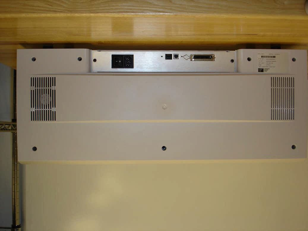
Technologies GY L G Y L EQUIPMENT FCC ID : MX5402920001 Exhibit 2 INTERNAL / EXTERNAL PHOTOS Page : 1/4 Written by : D. RAUDJanuary 18,2002Test report # : 019054DR 1. Printer Model 1 Printer Reference: P210 CEM Serial number: P210000548 Manual: P210 User’s Manual Figure 1: Tested equipment FRONT VIEW REAR VIEW Technologies GY L G Y L EQUIPMENT FCC ID : MX5402920001 Exhibit 2 INTERNAL / EXTERNAL PHOTOS Page : 2/4 Written by : D. RAUDJanuary 18,2002Test report # : 019054DR Figure 2: Location of RFID in the printer Printing Head Radio frequency identifier card Main Board Advanced card input Motor Advanced ribbon Motor Technologies GY L G Y L EQUIPMENT FCC ID : MX5402920001 Exhibit 2 INTERNAL / EXTERNAL PHOTOS Page : 3/4 Written by : D. RAUDJanuary 18,2002Test report # : 019054DR 2. Printer Model 2 Printer Reference: P310 CEM Serial number: None Manual: P310 User’s Manual Technologies GY L G Y L EQUIPMENT FCC ID : MX5402920001 Exhibit 2 INTERNAL / EXTERNAL PHOTOS Page : 4/4 Written by : D. RAUDJanuary 18,2002Test report # : 019054DR Magnetic card writer Motherboard USB option card Arcotronics Filter Smart card programming driver Radio Frequency Identifier card located under the magnetic writer card
Schematics
Technologies GY L G Y L EQUIPMENT FCC ID : MX5402920001 Exhibit 5 SCHEMATIC AND LAY OUT Page : 1/4 Written by : D. RAUDJanuary 18,2002Test report # : 019054DR 5.1 SCHEMATIC Technologies GY L G Y L EQUIPMENT FCC ID : MX5402920001 Exhibit 5 SCHEMATIC AND LAY OUT Page : 2/4 Written by : D. RAUDJanuary 18,2002Test report # : 019054DR 5.2 P210 RFID B OARD L AYOUT Integrated antenna Technologies GY L G Y L EQUIPMENT FCC ID : MX5402920001 Exhibit 5 SCHEMATIC AND LAY OUT Page : 3/4 Written by : D. RAUDJanuary 18,2002Test report # : 019054DR 5.3 P310 RFID B OARD L AYOUT Integrated antenna Technologies GY L G Y L EQUIPMENT FCC ID : MX5402920001 Exhibit 5 SCHEMATIC AND LAY OUT Page : 4/4 Written by : D. RAUDJanuary 18,2002Test report # : 019054DR 5.4 RFID ON PRINTING RIBBON EEPROM DIE Antenna Ribbon transceiver in normal use DIE position
Test Report
Technologies GY L G Y L FCC CERTIFICATION TEST REPORT EQUIPMENT FCC ID : MX5402920001 P210 Appendices Written by : D. RAUDJanuary 18, 2002Test report # : 019054DR P210 PRINTER MODEL DETAILED TEST RESULTS Technologies GY L G Y L FCC CERTIFICATION TEST REPORT EQUIPMENT FCC ID : MX5402920001 P210 Annex :1-1 Written by : D. RAUDJanuary 18, 2002Test report # : 019054DR Technologies GY L G Y L FCC CERTIFICATION TEST REPORT EQUIPMENT FCC ID : MX5402920001 P210 Annex :1-2 Written by : D. RAUDJanuary 18, 2002Test report # : 019054DR Technologies GY L G Y L FCC CERTIFICATION TEST REPORT EQUIPMENT FCC ID : MX5402920001 P210 Annex :1-3 Written by : D. RAUDJanuary 18, 2002Test report # : 019054DR Technologies GY L G Y L FCC CERTIFICATION TEST REPORT EQUIPMENT FCC ID : MX5402920001 P210 Annex :1-4 Written by : D. RAUDJanuary 18, 2002Test report # : 019054DR Technologies GY L G Y L FCC CERTIFICATION TEST REPORT EQUIPMENT FCC ID : MX5402920001 P210 Annex :1-5 Written by : D. RAUDJanuary 18, 2002Test report # : 019054DR Technologies GY L G Y L FCC CERTIFICATION TEST REPORT EQUIPMENT FCC ID : MX5402920001 P210 Annex :1-6 Written by : D. RAUDJanuary 18, 2002Test report # : 019054DR Technologies GY L G Y L FCC CERTIFICATION TEST REPORT EQUIPMENT FCC ID : MX5402920001 P210 Annex :1-7 Written by : D. RAUDJanuary 18, 2002Test report # : 019054DR Technologies GY L G Y L FCC CERTIFICATION TEST REPORT EQUIPMENT FCC ID : MX5402920001 P210 Annex :1-8 Written by : D. RAUDJanuary 18, 2002Test report # : 019054DR Technologies GY L G Y L FCC CERTIFICATION TEST REPORT EQUIPMENT FCC ID : MX5402920001 P210 Annex :1-9 Written by : D. RAUDJanuary 18, 2002Test report # : 019054DR Technologies GY L G Y L FCC CERTIFICATION TEST REPORT EQUIPMENT FCC ID : MX5402920001 P210 Annex :1-10 Written by : D. RAUDJanuary 18, 2002Test report # : 019054DR Technologies GY L G Y L FCC CERTIFICATION TEST REPORT EQUIPMENT FCC ID : MX5402920001 P210 Annex :1-11 Written by : D. RAUDJanuary 18, 2002Test report # : 019054DR Technologies GY L G Y L FCC CERTIFICATION TEST REPORT EQUIPMENT FCC ID : MX5402920001 P210 Annex :1-12 Written by : D. RAUDJanuary 18, 2002Test report # : 019054DR Technologies GY L G Y L FCC CERTIFICATION TEST REPORT EQUIPMENT FCC ID : MX5402920001 P210 Annex :1-13 Written by : D. RAUDJanuary 18, 2002Test report # : 019054DR Technologies GY L G Y L FCC CERTIFICATION TEST REPORT EQUIPMENT FCC ID : MX5402920001 P210 Annex :1-14 Written by : D. RAUDJanuary 18, 2002Test report # : 019054DR Technologies GY L G Y L FCC CERTIFICATION TEST REPORT EQUIPMENT FCC ID : MX5402920001 P210 Annex :1-15 Written by : D. RAUDJanuary 18, 2002Test report # : 019054DR Technologies GY L G Y L FCC CERTIFICATION TEST REPORT EQUIPMENT FCC ID : MX5402920001 P210 Annex :1-16 Written by : D. RAUDJanuary 18, 2002Test report # : 019054DR Technologies GY L G Y L FCC CERTIFICATION TEST REPORT EQUIPMENT FCC ID : MX5402920001 P210 Annex :2-1 Written by : D.RAUDJanuary 18, 2002Test report # : 019054DR Technologies GY L G Y L FCC CERTIFICATION TEST REPORT EQUIPMENT FCC ID : MX5402920001 P210 Annex :2-2 Written by : D.RAUDJanuary 18, 2002Test report # : 019054DR Technologies GY L G Y L FCC CERTIFICATION TEST REPORT EQUIPMENT FCC ID : MX5402920001 P210 Annex :2-3 Written by : D.RAUDJanuary 18, 2002Test report # : 019054DR
Test Report
Technologies GY L G Y L FCC CERTIFICATION TEST REPORT EQUIPMENT FCC ID : MX5402920001 P310 Appendices Written by : D. RAUDJanuary 18, 2002Test report # : 019054DR P310 PRINTER MODEL DETAILED TEST RESULTS Technologies GY L G Y L FCC CERTIFICATION TEST REPORT EQUIPMENT FCC ID : MX5402920001 P310 Annex :1-1 Written by : D. RAUDJanuary 18, 2002Test report # : 019054DR Technologies GY L G Y L FCC CERTIFICATION TEST REPORT EQUIPMENT FCC ID : MX5402920001 P310 Annex :1-2 Written by : D. RAUDJanuary 18, 2002Test report # : 019054DR Technologies GY L G Y L FCC CERTIFICATION TEST REPORT EQUIPMENT FCC ID : MX5402920001 P310 Annex :1-3 Written by : D. RAUDJanuary 18, 2002Test report # : 019054DR Technologies GY L G Y L FCC CERTIFICATION TEST REPORT EQUIPMENT FCC ID : MX5402920001 P310 Annex :1-4 Written by : D. RAUDJanuary 18, 2002Test report # : 019054DR Technologies GY L G Y L FCC CERTIFICATION TEST REPORT EQUIPMENT FCC ID : MX5402920001 P310 Annex :1-5 Written by : D. RAUDJanuary 18, 2002Test report # : 019054DR Technologies GY L G Y L FCC CERTIFICATION TEST REPORT EQUIPMENT FCC ID : MX5402920001 P310 Annex :1-6 Written by : D. RAUDJanuary 18, 2002Test report # : 019054DR Technologies GY L G Y L FCC CERTIFICATION TEST REPORT EQUIPMENT FCC ID : MX5402920001 P310 Annex :1-7 Written by : D. RAUDJanuary 18, 2002Test report # : 019054DR Technologies GY L G Y L FCC CERTIFICATION TEST REPORT EQUIPMENT FCC ID : MX5402920001 P310 Annex :1-8 Written by : D. RAUDJanuary 18, 2002Test report # : 019054DR Technologies GY L G Y L FCC CERTIFICATION TEST REPORT EQUIPMENT FCC ID : MX5402920001 Annex :2-1 Written by : D.RAUDJanuary 18, 2002Test report # : 019054DR Technologies GY L G Y L FCC CERTIFICATION TEST REPORT EQUIPMENT FCC ID : MX5402920001 Annex :2-2 Written by : D.RAUDJanuary 18, 2002Test report # : 019054DR Technologies GY L G Y L FCC CERTIFICATION TEST REPORT EQUIPMENT FCC ID : MX5402920001 Annex :2-3 Written by : D.RAUDJanuary 18, 2002Test report # : 019054DR Technologies GY L G Y L FCC CERTIFICATION TEST REPORT EQUIPMENT FCC ID : MX5402920001 Annex :2-4 Written by : D.RAUDJanuary 18, 2002Test report # : 019054DR Technologies GY L G Y L FCC CERTIFICATION TEST REPORT EQUIPMENT FCC ID : MX5402920001 Annex :2-5 Written by : D.RAUDJanuary 18, 2002Test report # : 019054DR Technologies GY L G Y L FCC CERTIFICATION TEST REPORT EQUIPMENT FCC ID : MX5402920001 Annex :2-6 Written by : D.RAUDJanuary 18, 2002Test report # : 019054DR
Test Report
Technologies GY L G Y L FCC CERTIFICATION TEST REPORT EQUIPMENT FCC ID : MX5402920001 Page : 1/12 Written by : D. RAUDJanuary 18,2002Test report # : 019054DR TEST LAB FCC ID: I6U This report concerns :Original grant ! !! ! Class II change Equipment tested : Radio Frequency Identifier for CARD PRINTER Equipment FCC ID : MX5402920001 Designed by : ZEBRA TECHNOLOGIES ZI rue d’AMSTERDAM 44470 VARADES - FRANCE Manufactured by : ELTRON 1001 Flynn Road CAMARILLO - CA 93012 Deferred grant requested per 47 CFR 0.457 (d)(1)(ii) YESNO ! !! ! if yes, defer until : Company Named agrees to notify the Commission by : of the intended date of announcement of the product so that the grant can be issued on the date Transition rules requested per 15.37? YESNO ! !! ! If no, assumed Part 15, Subpart B for intentional or unintentional radiator The new 47 CFR [10-1-96 edition] provision Technical control: Olivier ROY GYL technologies 1, rue Fleming 49066 ANGERS Tel. : 02.41.36.22.33 Fax : 02.41.36.22.23 Quality Control: Lucien MONTIEL Technologies GY L G Y L FCC CERTIFICATION TEST REPORT EQUIPMENT FCC ID : MX5402920001 Page : 2/12 Written by : D. RAUDJanuary 18,2002Test report # : 019054DR TABLE OF CONTENTS Page 1E.U.T TECHNICAL DESCRIPTION __________________________________________ 3 1.1 Product description _____________________________________________________________ 3 1.2 List of EMI critical components ___________________________________________________ 3 1.3 Tested systems details____________________________________________________________ 3 1.4 Test Methodology and procedure __________________________________________________ 4 1.5 Test site _______________________________________________________________________ 4 1.6 List of measurement apparatus____________________________________________________ 4 2SYSTEM TEST CONFIGURATION ___________________________________________ 5 2.1 Justification ____________________________________________________________________ 5 2.2 EUT TEST CONFIGURATION DIAGRAM ________________________________________ 5 2.3 EUT EXERCISING CONDITIONS ________________________________________________ 6 3POWER LINE CONDUCTED EMISSION (§ 15.107 class B)_______________________ 7 3.1 Test results measurements ________________________________________________________ 7 3.2 Table 1 - Combination of conducted emission testing for the p210 model _________________ 7 3.3 Summary of 6 highest signals per wire measured on each configuration __________________ 8 4OPEN FIELD RADIATED EMISSION (§ 15.109 class B) _________________________ 9 4.1 Test results measurements ________________________________________________________ 9 4.2 FIELD STRENGTH CALCULATION _____________________________________________ 9 4.3 Summary of 6 highest signals measured on the P210 configuration ______________________ 9 4.4 Summary of 6 highest signals measured on the P310 configuration _____________________ 10 5R ADIATOR F IELD STRENGTH VERSUS PART 15 S UBPART C §15.225, 15.209, 15.205 _______ 11 5.1 Measurement of frequency stability( §15.225 (c)) ____________________________________ 11 5.2 Harmonic level measurement ____________________________________________________ 11 Technologies GY L G Y L FCC CERTIFICATION TEST REPORT EQUIPMENT FCC ID : MX5402920001 Page : 3/12 Written by : D. RAUDJanuary 18,2002Test report # : 019054DR 1 E.U.T TECHNICAL DESCRIPTION 1.1 P RODUCT DESCRIPTION The 13,56 MHz Radio Frequency IDentifier (RFID) is composed of : A transceiver (emitter and receiver ) placed on an electronic board (see exhibit 5) A passive transceiver embedded in the printing ribbon frame (see exhibit 5) This features is used in printer family range whose purpose is printing cards. Its primary function is to check if the inserted printing ribbon is the right one. Pictures given in exhibit 2. show how the RFID cards are mounted on two different printer models 1.2 L IST OF EMI CRITICAL COMPONENTS ITEMReferenceFrequencyManufacturer OscillatorABLS-10.000-18-R70-B-4-Y-FT 10.00 MHzPrime Elect OscillatorABLS-13.5600-18-R70-B-4-Y-FT 13.56 MHzPrime Elect Ferrite beadSteward: LI0805H121RKent Elect. Inductance0805CS-681XJBC680 nH 5%Coilcraft Inductance0805CS-391XGBC390 nH 2%Coilcraft Inductance0805CS-821XGBC820 nH 2%Coilcraft 1.3 T ESTED SYSTEMS DETAILS The FCC IDs for all equipment, plus description of all cables used in the tested system (including inserted cards, which have grants) are: Description Model & Serial number FCC IDCable descriptionCable termination Length (m) Radio Frequency Identifier (RFID)Submitted for GrantNoneNoneNone Printer Model 210 FCC Class B Test report 019054 DK serial shielded cable parallel shielded cablePlastic molded 2 m 1,8 m DELL Portable PCDoCUSB shielded cablemetallic1,5 m EOS ZVC65SG24E AC/DC adapter or PowerBox SPN-270-24 AC/DC adapter unshielded cable plastic molded jack 1.5m Printer Model 310 FCC Class B Test report 019041CH USB shielded cable parallel shielded cable Plastic molded2 m 1,8 m NEC POWERMATE PC model NLX7YA06402US DoC USB shielded cable metallic1,5 m Zenith Display ZCM1426-XT CKLHCM-427 shielded cable Plastic molded1m Mouse Microsoft C3KKMP5 unshielded cable Plastic molded1.5 m Technologies GY L G Y L FCC CERTIFICATION TEST REPORT EQUIPMENT FCC ID : MX5402920001 Page : 4/12 Written by : D. RAUDJanuary 18,2002Test report # : 019054DR 1.4 T EST M ETHODOLOGY AND PROCEDURE Both conducted and radiated testing were performed in accordance with ANSI C63.4 procedure, as revised in 1992. The specification used was the Class B limits of FCC Rules Part 15 Subpart B for conductive (§ 15- 107) and radiated (§ 15-109) interference measurements and Subpart C (§ 15.201 to 15.209 and §15.225) for intentional radiator. Final radiated measurement is performed with an antenna located at 3 meters distance from EUT (Preliminary radiated emission test (prescan) was realized at a distance of 1 meter in the underground of open area test site) 1.5 T EST SITE The open area test site and conducted measurement facility use…
Text truncated - open the document above for the full version.
Test Setup Photos
Technologies GY L G Y L EQUIPMENT FCC ID : MX5402920001 Exhibit 6 TEST SET UP PHOTOS Page : 1/5 Written by : D. RAUDJanuary 18,2002Test report # : 019054DR C ONDUCTED EMISSION T EST SET UP P210 PRINTER Technologies GY L G Y L EQUIPMENT FCC ID : MX5402920001 Exhibit 6 TEST SET UP PHOTOS Page : 2/5 Written by : D. RAUDJanuary 18,2002Test report # : 019054DR P310 PRINTER Technologies GY L G Y L EQUIPMENT FCC ID : MX5402920001 Exhibit 6 TEST SET UP PHOTOS Page : 3/5 Written by : D. RAUDJanuary 18,2002Test report # : 019054DR R ADIATED F IELD T EST SET UP P210 set up Technologies GY L G Y L EQUIPMENT FCC ID : MX5402920001 Exhibit 6 TEST SET UP PHOTOS Page : 4/5 Written by : D. RAUDJanuary 18,2002Test report # : 019054DR P310 SET UP Technologies GY L G Y L EQUIPMENT FCC ID : MX5402920001 Exhibit 6 TEST SET UP PHOTOS Page : 5/5 Written by : D. RAUDJanuary 18,2002Test report # : 019054DR E MITTED P OWER AND SPURIOUS TEST SET UP
Contact Information
Applicant
Zaven Mangassarian(Compliance Engineer)
Technical Contact
ZEBRA TECHNOLOGIESPhilippe JOURDON
[email protected]+33 2 40 09 70 75
ZI rue d'Amsterdam · VARADES · France
Non-Technical Contact
ZEBRA TECHNOLOGIESPhilippe JOURDON
[email protected]+33 2 40 09 70 75
Test Firm
EMITECH ANGERSOlivier ROY
Technical Specifications
| # | Rule Parts | Frequency Range | Power Output | Tolerance |
|---|---|---|---|---|
| 1 | 15C | 13.56 MHz - 13.56 MHz | - | 0.0100000000 % |
Other Applications from Eltron Products
MX5-P640I
Jun 01, 2005Radio frequency identifier
Equipment Class
DXX - Part 15 Low Power Communication Device Transmitter
MX5-S820I
May 05, 2003Card Printer with RFID and Laminator
Equipment Class
DXX - Part 15 Low Power Communication Device Transmitter
MX5-P2222
Nov 08, 1999DXX - Part 15 Low Power Communication Device Transmitter
Equipment Class
DXX - Part 15 Low Power Communication Device TransmitterMX521631
Sep 16, 1996JBP - Part 15 Class B Computing Device Peripheral
Equipment Class
JBP - Part 15 Class B Computing Device PeripheralMX5-TIGER
May 28, 1996Label Printer
Equipment Class
JBP - Part 15 Class B Computing Device Peripheral