MXF-HNGR02Wireless TV connect
Gemtek Technology Co., Ltd.
Click to zoom
Application Details
- Equipment Class
- NII - Unlicensed National Information Infrastructure TX
- Date of Grant
- Dec 13, 2011
- Application Purpose
- Original Equipment
- Date of Application
- Dec 11, 2011
- Equipment Note
- Wireless TV connect
- Frequency Range
- 5180.00000000 - 5240.00000000
- Company
- Gemtek Technology Co., Ltd.
- Country
- Taiwan
Documents & Files
Document Text
Text extracted from the exhibit documents filed with the FCC. Open a document above to read the original.
Users Manual
1 3 2 Product: Wireless HDMI Document: Consumer QSPPart number: 6213 61- 0 01 Color page 1: CMYK + PMS 640Flat size: 27.5 x 17 Color page 2: CMYK + PMS 640Finished size: 5.5 x 8.5 Fold 1: Horizontal, in half Fold 2: 5-panel accordion 6620 Cypresswood Drive Suite 120 Spring, TX 77379 832.717.4331 English on front (outside)English on front (outside) The power light on the TV adapter does not turn on. •Ensure that the power adapter is securely connected to the TV adapter and to a wall outlet. •Plug another device into the wall outlet to ensure that the outlet is functioning. The link light on the TV adapter does not turn on. •Ensure that the HDMI cables are securely connected to the components. The link light turns on but continues to blink. •Wait a few minutes for the components to complete initialization. You should see messages on the computer and/or TV screen. It may take up to 5 minutes for initialization to complete. •Ensure that you have connected the components according to the instructions. The TV does not display the image that is on the computer. •Press the input source button on the TV to select the HDMI input. Nothing happens when I press the Reset button on the PC adapter. •The Reset button on the PC adapter is only used for software upgrades. 2 Connect the TV adapter to your TV or other external display and to external power. ComponentsTroubleshootingRegulatory and Safety Notices 3 If you connected to a TV, press the input source button on the TV to select the HDMI input. When the components are connected correctly and the correct source is selected, the image on the computer display will be shown on the TV. NOTE: Make sure that your computer and TV are both powered on. NOTE: If you are using an external display other than a TV, the display may not have an input source input button and the source may cycle automatically. NOTE: It may take a few seconds for the adapters to link to each other and for the image on the computer to display on the TV (or other external display). Issue Resolution 1 *The Setup menu allows you to add or remove a video source, modify a video source name, disconnect a wireless link, and exit the menu. To add or remove a video source, or disconnect a wireless link: 1. Press the Menu button twice. 2. Press the Down or Up button to highlight Add or Remove Video Source or Disconnect Wireless Link. 3. Press the Menu button to select the item and execute the process. 4. Press the Menu button again to confirm adding or removing a video source, or disconnecting a wireless link. NOTE: To add a new video source after removing one, repeat the above process. To modify the video source name: 1. Press the Menu button twice. 2. Press the Down button to highlight Modify Video Source name. 3. Press the Menu button to execute the naming process. 4. Press the Menu button to select the video source to be renamed. 5. Use the Up or Down buttons to move horizontally and highlight the character to be changed. 6. Press the Menu button to select the character to be changed. 7. Press the Up or Down buttons to change the character. 8. Press the Menu button to select the new character. 9. Press and hold the Menu button to select Save or Exit Video Source name. After the Save or Exit function has been selected, the display returns to the main menu. NOTE: You may need to upgrade the software on your adapter to ensure compatibility with devices produced by other manufacturers. When it’s available, you can download updated software with installation instructions from http://www.hp.com/support. TV Adapter 1 HDMI connector: Connects the PC adapter to your computer. 2 Link light • On: The adapter is linked to the TV adapter. • Blinking: The adapter is attempting to link to the TV adapter. 3 USB connector: Connects the USB power cable to the PC adapter. 4 Reset button* 1 Up button: Scrolls up through menu. 2 Down button: Scrolls down through menu. 3 Menu/Select button: Displays the Setup menu* and selects items. 4 HDMI port: Connects the TV adapter to your TV or display. 5 Micro USB power port: Connects the TV adapter to external power, and can also be used to upgrade the HP Wireless TV Connect firmware. 6 Link light • Blinking blue: The TV adapter is attempting to link to the PC adapter. • Solid white: The TV adapter is linked to the PC adapter. 7 Power light • On: The adapter is on. • Off: The adapter is off. PC Adapter 1 Power adapter and cable: Connects the TV adapter to external power. 2 HDMI cable: Connects the TV adapter to your TV or other external display 3 USB cable: Connects the PC adapter to your computer. Cables Federal Communications Commission notice This equipment has been tested and found to comply with the limits for a Class B digital device, pursuant to Part 15 of the FCC Rules. These limits are designed to provide reasonable protection against harmful interference in a residential installation. This equipment generates, uses, and can radiate radio frequency energy and, if not installed and used in accordance with the instructions, may cause harmful interference to radio communications. However, there is no guarantee that interference will not occur in a particular installation. If this equipment does cause harmful interference to radio or television reception, which can be determined by turning the equipment off and on, the user is encouraged to try to correct the interference by one or more of the following measures: • Reorient or relocate the receiving antenna. • Increase the separation between the equipment and receiver. • Connect the equipment to an outlet on a circuit different from that to which the receiver is connected. • Consult the dealer or an experienced radio or television technician for help. Modifications The FCC requires the user to be notified that any changes or modifications made to this device that are not expressly approved by HP may void the user’s authority to operate the equipment. Cables To maintain compliance with FCC Rules and Regulations, con…
Text truncated - open the document above for the full version.
External Photos
Page 1 CONSTRUCTION PHOTOS OF EUT Page 2
ID Label/Location Info
Barbossa TX WMDA-133AN_US Barbossa TX WMDA-133AN_EU/UK PMS877C BLACK Barbossa RX WMTA-156AN US Regulatory Model: HSTNN-GR01 Product of China This class [B] digital apparatus complies with Canadian ICES-003. IC: 466Q-HNGR01 FCC ID: MXF-HNGR01 INPUT: 5V 2A Factory ID: cs001 E218211 Barbossa RX WMTA-156AN EU/UK Regulatory Model: HSTNN-GR01 Product of China This class [B] digital apparatus complies with Canadian ICES-003. IC: 466Q-HNGR01 FCC ID: MXF-HNGR01 INPUT: 5V 2A T Regulatory Model: HSTNN-GR01 Product of China This class [B] digital apparatus complies with Canadian ICES-003. IC: 466Q-HNGR01 FCC ID: MXF-HNGR01 INPUT: 5V 2A Factory ID: cs001 Spares PN: 664870-001 HP SKU PN: QE389AA#ABC Serial: Q09GT000DXI Spares PN: 667830-001 HP SKU PN: QE389AA#ABB Regulatory Model: HSTNN-GR01 Product of China This class [B] digital apparatus complies with Canadian ICES-003. IC: 466Q-HNGR01 FCC ID: MXF-HNGR01 INPUT: 5V 2A Spares PN: 667830-001 HP SKU PN: QE389AA#ABB Serial: Q09GT000DXI Spares PN: 664870-001 HP SKU PN: QE389AA#ABC Spares PN: 664871-001 Regulatory Model: HSTNN-GR02 N: 664871-001Spares P Regulatory Model: HSTNN-GR02 FCC ID: MXF-HNGR02 IC: 466Q-HNGR02 Spares PN: 664871-001 Regulatory Model: HSTNN-GR02 Serial: Q09GT000DXI Serial: Q09GT000DXI N: 664871-001Spares P Regulatory Model: HSTNN-GR02 FCC ID: MXF-HNGR02 IC: 466Q-HNGR02 E218211 Factory ID: cs001 E218211 Factory ID: cs001 E218211
Internal Photos
Page 3 Page 4 Page 5 Page 6
Operational Description
FCC ID: MXF-HNGR02 Report No.: RF111114C07 Operational Description This device is a Wireless TV connect, which operates in 5GHz band, the maximum data rate could be up to 100kbps which OFDM technique. The transmitter of the EUT is powered by 5Vdc from host equipment. The antenna is Chip antenna without antenna connector. The other instruction, please have a look at the users manual. FCC 15.407(c) states: The device shall automatically discontinue transmission in case of either absence of information to transmit or operational failure. These provisions are not intended to preclude the transmission of control or signaling information or the use of repetitive codes used by certain digital technologies to complete frame or burst intervals. Applicants shall include in their application for equipment authorization a description of how this requirement is met” Data transmission is always initiated by software, which is then pass down through the MAC, through the digital and analog baseband, and finally to the RF chip. Several special packets (ACKs, CTS, PSPoll, etc...) are initiated by the MAC. There are the only ways the digital baseband portion will turn on the RF transmitter, which it then turns off at the end of the packet. Therefore, the transmitter will be on only while one of the aforementioned packets are being transmitted.
RF Exposure Info
Report No.: SA111114C07 Report Format Version 4.0.0 1 RF EXPOSURE REPORT REPORT NO.: SA111114C07 MODEL NO.: HSTNN-GR02 FCC ID: MXF-HNGR02 RECEIVED: Nov. 14, 2011 TESTED: Nov. 15 ~ Nov. 18, 2011 ISSUED: Nov. 28, 2011 APPLICANT: Gemtek Technology Co., Ltd. ADDRESS: No.15-1, Zhonghua Rd, Hsinchu Industrial Park , Hsinchu County, Taiwan,R.O.C.303 ISSUED BY: Bureau Veritas Consumer Products Services (H.K.) Ltd., Taoyuan Branch LAB ADDRESS: No. 47, 14th Ling, Chia Pau Vil., Lin Kou Dist., New Taipei City, Taiwan ( R.O.C ) TEST LOCATION: No. 19, Hwa Ya 2nd Rd, Wen Hwa Tsuen, Kwei Shan Hsiang, Taoyuan Hsien 333, Taiwan, R.O.C. This test report consists of 5 pages in total. It may be duplicated completely for legal use with the approval of the applicant. It should not be reproduced, except in full, without the written approval of our laboratory. The client should not use it to claim product, certification, approval, or endorsement by any government agency. The test results in the report only apply to the tested sample. Report No.: SA111114C07 Report Format Version 4.0.0 2 TABLE OF CONTENTS RELEASE CONTROL RECORD.....................................................................................3 1. CERTIFICATION ..............................................................................................4 2. RF EXPOSURE ................................................................................................5 Report No.: SA111114C07 Report Format Version 4.0.0 3 RELEASE CONTROL RECORD ISSUE NO. REASON FOR CHANGE DATE ISSUED Original release NA Nov. 28, 2011 Report No.: SA111114C07 Report Format Version 4.0.0 4 1. CERTIFICATION PRODUCT: Wireless TV connect MODEL: HSTNN-GR02 BRAND: hp APPLICANT: Gemtek Technology Co., Ltd. TESTED: Nov. 15 ~ Nov. 18, 2011 TEST SAMPLE: ENGINEERING SAMPLE STANDARDS: FCC Part 2 (Section 2.1091) FCC OET Bulletin 65, Supplement C (01-01) IEEE C95.1 The above equipment (Model: HSTNN-GR02) has been tested by Bureau Veritas Consumer Products Services (H.K.) Ltd., Taoyuan Branch, and found compliance with the requirement of the above standards. The test record, data evaluation & Equipment Under Test (EUT) configurations represented herein are true and accurate accounts of the measurements of the sample’s EMC characteristics under the conditions specified in this report. PREPARED BY : , DATE:Nov. 28, 2011 Ivonne Wu / Senior Specialist APPROVED BY : , DATE: Nov. 28, 2011 Gary Chang / Technical Manager Report No.: SA111114C07 Report Format Version 4.0.0 5 2. RF EXPOSURE No Evaluation Required if power is below this threshold: F (GHz) mW 5180-5240 11.45 5745-5805 10.34 Maximum measured transmitter Average power: F (GHz) Pout (dBm) Pout (dBm) Pout (mW) Conducted Power 6.0 4.0 5180-5240 EIRP Power 8.0 6.3 Conducted Power 6.1 4.1 5745-5805 EIRP Power 8.1 6.5 Note: The antenna is Chip antenna with 2 dBi gain. Conclusion: No SAR evaluation required since Transmitter Pout is below FCC threshold.
Test Report
Report No.: RF111114C07 1 Report Format Version 4.1.0 FCC TEST REPORT (15.247) REPORT NO.: RF111114C07 MODEL NO.: HSTNN-GR02 FCC ID: MXF-HNGR02 RECEIVED: Nov. 14, 2011 TESTED: Nov. 15 ~ Nov. 18, 2011 ISSUED: Nov. 28, 2011 APPLICANT: Gemtek Technology Co., Ltd. ADDRESS: No.15-1, Zhonghua Rd, Hsinchu Industrial Park , Hsinchu County, Taiwan,R.O.C.303 ISSUED BY: Bureau Veritas Consumer Products Services (H.K.) Ltd., Taoyuan Branch LAB ADDRESS: No. 47, 14th Ling, Chia Pau Vil., Lin Kou Dist., New Taipei City, Taiwan ( R.O.C ) TEST LOCATION: No. 19, Hwa Ya 2nd Rd, Wen Hwa Tsuen, Kwei Shan Hsiang, Taoyuan Hsien 333, Taiwan, R.O.C. This test report consists of 42 pages in total. It may be duplicated completely for legal use with the approval of the applicant. It should not be reproduced except in full, without the written approval of our laboratory. The client should not use it to claim product, certification, approval or endorsement by TAF or any government agency. The test results in the report only apply to the tested sample. Report No.: RF111114C07 2 Report Format Version 4.1.0 TABLE OF CONTENTS RELEASE CONTROL RECORD.............................................................................................. 4 1. CERTIFICATION........................................................................................................... 5 2. SUMMARY OF TEST RESULTS .................................................................................. 6 2.1 MEASUREMENT UNCERTAINTY................................................................................ 6 3. GENERAL INFORMATION ........................................................................................... 7 3.1 GENERAL DESCRIPTION OF EUT ............................................................................. 7 3.2 DESCRIPTION OF TEST MODES ............................................................................... 8 3.2.1 CONFIGURATION OF SYSTEM UNDER TEST .......................................................... 9 3.2.2 DESCRIPTION OF SUPPORT UNITS ......................................................................... 9 3.2.3 TEST MODE APPLICABILITY AND TESTED CHANNEL DETAIL ............................. 10 3.3 GENERAL DESCRIPTION OF APPLIED STANDARDS ............................................ 12 4. TEST TYPES AND RESULTS .................................................................................... 13 4.1 RADIATED EMISSION AND BANDEDGE MEASUREMENT..................................... 13 4.1.1 LIMITS OF RADIATED EMISSION AND BANDEDGE MEASUREMENT .................. 13 4.1.2 TEST INSTRUMENTS................................................................................................ 14 4.1.3 TEST PROCEDURES ................................................................................................ 15 4.1.4 DEVIATION FROM TEST STANDARD....................................................................... 15 4.1.5 TEST SETUP.............................................................................................................. 16 4.1.6 EUT OPERATING CONDITIONS ............................................................................... 16 4.1.7 TEST RESULTS ......................................................................................................... 17 4.2 CONDUCTED EMISSION MEASUREMENT ............................................................. 23 4.2.1 LIMITS OF CONDUCTED EMISSION MEASUREMENT........................................... 23 4.2.2 T EST INSTRUMENTS............................................................................................... 23 4.2.3 TEST PROCEDURES ................................................................................................ 24 4.2.4 DEVIATION FROM TEST STANDARD....................................................................... 24 4.2.5 TEST SETUP.............................................................................................................. 25 4.2.6 EUT OPERATING CONDITIONS ............................................................................... 25 4.2.7 TEST RESULTS ......................................................................................................... 26 4.3 6DB BANDWIDTH MEASUREMENT ......................................................................... 28 4.3.1 LIMITS OF 6DB BANDWIDTH MEASUREMENT ...................................................... 28 4.3.2 TEST SETUP.............................................................................................................. 28 4.3.3 TEST INSTRUMENTS................................................................................................ 28 4.3.4 TEST PROCEDURE................................................................................................... 28 4.3.5 DEVIATION FROM TEST STANDARD....................................................................... 28 4.3.6 EUT OPERATING CONDITIONS ............................................................................... 28 4.3.7 TEST RESULTS ......................................................................................................... 29 4.4 CONDUCTED OUTPUT POWER............................................................................... 30 Report No.: RF111114C07 3 Report Format Version 4.1.0 4.4.1 LIMITS OF MAXIMUM OUTPUT POWER MEASUREMENT..................................... 30 4.4.2 TEST SETUP.............................................................................................................. 30 4.4.3 INSTRUMENTS .......................................................................................................... 30 4.4.4 TEST PROCEDURES ................................................................................................ 30 4.4.5 DEVIATION FROM TEST STANDARD....................................................................... 30 4.4.6 EUT OPERATING CONDITIONS ..........................................................…
Text truncated - open the document above for the full version.
Test Report
Report No.: RF111114C07-1 1 Report Format Version 4.1.0 FCC TEST REPORT (15.407) REPORT NO.: RF111114C07-1 MODEL NO.: HSTNN-GR02 FCC ID: MXF-HNGR02 RECEIVED: Nov. 14, 2011 TESTED: Nov. 15 ~ Nov. 18, 2011 ISSUED: Nov. 28, 2011 APPLICANT: Gemtek Technology Co., Ltd. ADDRESS: No.15-1, Zhonghua Rd, Hsinchu Industrial Park , Hsinchu County, Taiwan,R.O.C.303 ISSUED BY: Bureau Veritas Consumer Products Services (H.K.) Ltd., Taoyuan Branch LAB ADDRESS: No. 47, 14th Ling, Chia Pau Vil., Lin Kou Dist., New Taipei City, Taiwan ( R.O.C ) TEST LOCATION: No. 19, Hwa Ya 2nd Rd, Wen Hwa Tsuen, Kwei Shan Hsiang, Taoyuan Hsien 333, Taiwan, R.O.C. This test report consists of 41 pages in total. It may be duplicated completely for legal use with the approval of the applicant. It should not be reproduced except in full, without the written approval of our laboratory. The client should not use it to claim product, certification, approval or endorsement by TAF or any government agency. The test results in the report only apply to the tested sample. Report No.: RF111114C07-1 2 Report Format Version 4.1.0 TABLE OF CONTENTS RELEASE CONTROL RECORD.............................................................................................. 4 1. CERTIFICATION........................................................................................................... 5 2. SUMMARY OF TEST RESULTS .................................................................................. 6 2.1 MEASUREMENT UNCERTAINTY................................................................................ 6 3. GENERAL INFORMATION ........................................................................................... 7 3.1 GENERAL DESCRIPTION OF EUT ............................................................................. 7 3.2 DESCRIPTION OF TEST MODES ............................................................................... 8 3.2.1 CONFIGURATION OF SYSTEM UNDER TEST .......................................................... 8 3.2.2 DESCRIPTION OF SUPPORT UNITS ......................................................................... 8 3.2.3 TEST MODE APPLICABILITY AND TESTED CHANNEL DETAIL ............................... 9 3.3 GENERAL DESCRIPTION OF APPLIED STANDARDS ............................................ 10 4. TEST TYPES AND RESULTS .................................................................................... 11 4.1 RADIATED EMISSION AND BANDEDGE MEASUREMENT..................................... 11 4.1.1 LIMITS OF RADIATED EMISSION AND BANDEDGE MEASUREMENT .................. 11 4.1.2 LIMITS OF UNWANTED EMISSION OUT OF THE RESTRICTED BANDS .............. 11 4.1.3 TEST INSTRUMENTS................................................................................................ 12 4.1.4 TEST PROCEDURES ................................................................................................ 13 4.1.5 DEVIATION FROM TEST STANDARD....................................................................... 13 4.1.6 TEST SETUP.............................................................................................................. 14 4.1.7 EUT OPERATING CONDITION.................................................................................. 14 4.1.8 TEST RESULTS ......................................................................................................... 15 4.2 CONDUCTED EMISSION MEASUREMENT ............................................................. 21 4.2.1 LIMITS OF CONDUCTED EMISSION MEASUREMENT........................................... 21 4.2.2 TEST INSTRUMENTS................................................................................................ 21 4.2.3 TEST PROCEDURES ................................................................................................ 22 4.2.4 DEVIATION FROM TEST STANDARD....................................................................... 22 4.2.5 TEST SETUP.............................................................................................................. 23 4.2.6 EUT OPERATING CONDITIONS ............................................................................... 23 4.2.7 TEST RESULTS ......................................................................................................... 24 4.3 MAXIMUM CONDUCTED OUTPUT POWER MEASUREMENT ............................... 26 4.3.1 LIMITS OF MAXIMUM CONDUCTED OUTPUT POWER MEASUREMENT............. 26 4.3.2 TEST SETUP.............................................................................................................. 26 4.3.3 TEST INSTRUMENTS................................................................................................ 26 4.3.4 TEST PROCEDURE................................................................................................... 27 4.3.5 DEVIATION FROM TEST STANDARD....................................................................... 27 4.3.6 EUT OPERATING CONDITIONS ............................................................................... 27 4.3.7 TEST RESULTS ......................................................................................................... 28 Report No.: RF111114C07-1 3 Report Format Version 4.1.0 4.4 PEAK POWER EXCURSION MEASUREMENT ........................................................ 29 4.4.1 LIMITS OF PEAK POWER EXCURSION MEASUREMENT...................................... 29 4.4.2 TEST SETUP.............................................................................................................. 29 4.4.3 TEST INSTRUMENTS................................................................................................ 29 4.4.4 TEST PROCEDURE................................................................................................... 29 4.4.5 DEVIATION FROM TEST STANDARD....................................................................... 29 4.4.6 EUT OPERATING CONDITIONS ..................................…
Text truncated - open the document above for the full version.
Test Setup Photos
1 PHOTOGRAPHS OF THE TEST CONFIGURATION CONDUCTED EMISSION TEST 2 RADIATED EMISSION TEST
Contact Information
Applicant
Adam Wang(Manager)
Technical Contact
Bureau Veritas CPS (H.K.) Ltd. Taoyuan BranchGary Chang
[email protected]886-3-3183232
No. 19, Hwa Ya 2nd Rd., Kwei Shan Hsiang · Taoyuan Hsien · Taiwan
Non-Technical Contact
Bureau Veritas CPS (H.K.) Ltd. Taoyuan BranchNatacha Chen
[email protected]886-3-3183232
Test Firm
Bureau Veritas CPS (H.K.) Ltd. Taoyuan BranchRichard Chen
Technical Specifications
| # | Rule Parts | Frequency Range | Power Output |
|---|---|---|---|
| 1 | 15E | 5.18 GHz - 5.24 GHz | 4.00 mW |
Other Applications from Gemtek Technology Co., Ltd.
MXF-WRTQ411BE
Jul 16, 2026Wi-Fi 7 Tri-Band Router
Equipment Class
6ID - 15E 6 GHz Low Power Indoor Access PointMXF-XR1710G
Apr 18, 2024Wi-Fi 7 Router
Equipment Class
NII - Unlicensed National Information Infrastructure TX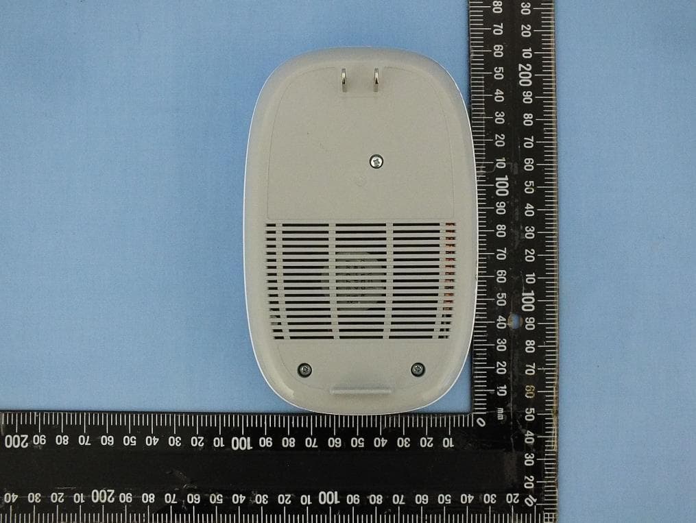
MXF-W1701K
Oct 17, 2023Tri-Band AP
Equipment Class
6ID - 15E 6 GHz Low Power Indoor Access Point
MXF-EL4000
Mar 01, 2022Wireless Home Internet
Equipment Class
NII - Unlicensed National Information Infrastructure TX
MXF-C5500XK
Jul 28, 2021C5500XK Modem
Equipment Class
DSS - Part 15 Spread Spectrum Transmitter