MXF-POCHANNELPOCHANNEL
Gemtek Technology Co., Ltd.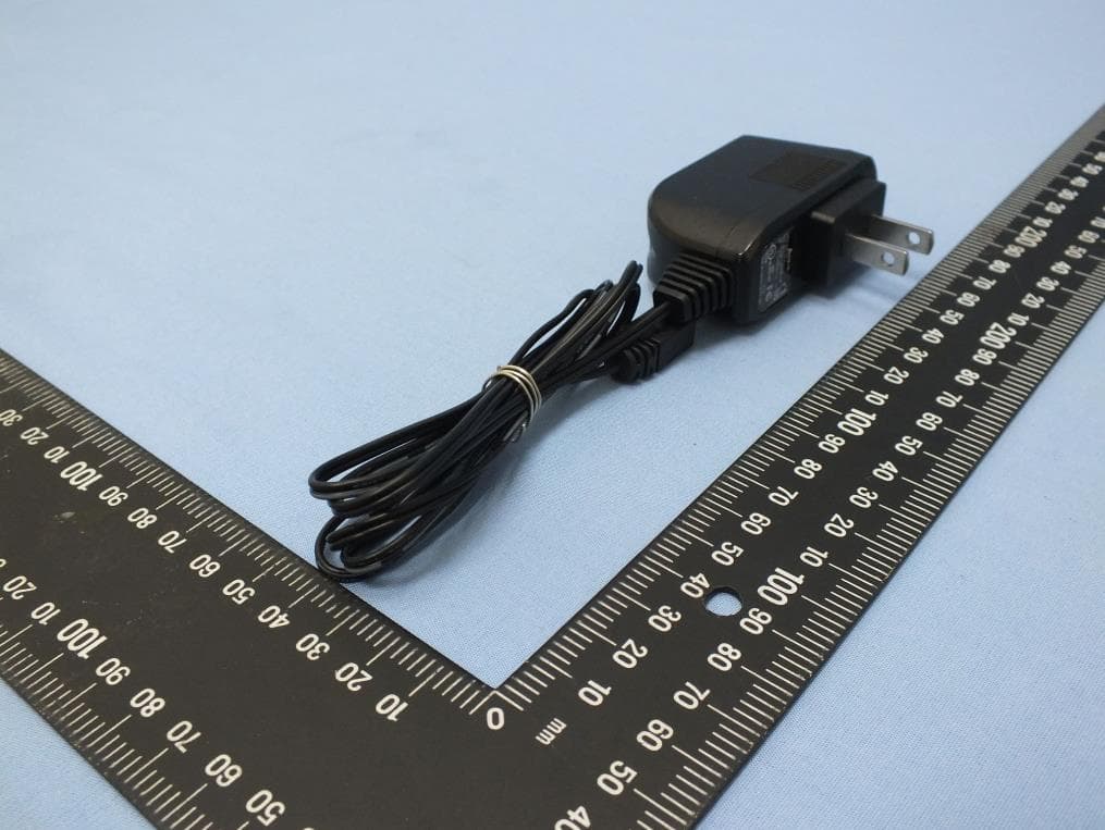
Click to zoom
Application Details
- Equipment Class
- DTS - Digital Transmission System
- Date of Grant
- Feb 16, 2014
- Application Purpose
- Original Equipment
- Date of Application
- Feb 12, 2014
- Equipment Note
- POCHANNEL
- Frequency Range
- 2412.00000000 - 2462.00000000
- Company
- Gemtek Technology Co., Ltd.
- Country
- Taiwan
Documents & Files
Document Text
Text extracted from the exhibit documents filed with the FCC. Open a document above to read the original.
Users Manual
po channel Quick Installation Guide Warning do not to spill water A computer or laptop that had internet access. A valid gmail accountLocal network (wireless) with internet access (will require access rights if protected) or an Android phone (Android 2.3.5 or later) with internet access. A display (TV or monitor) with HDMI input connection. Upon opening your newly purchased UtubeBox, please confirm that you have received the following contents! Connect HDMI cable to UtubeBox HDMI connector and display’s HDMI input connector. 1 1 3 2 Connect the power adaptor provided to UtubeBox and to a household wall power. 2 A language selection prompt will show. Select your preferred language. 3 Detected WiFi signals will appear. Select the WiFi signal you want to connect to, enter password. 4 An installation download message should appear and if not, please go back to previous step and try to connect to the internet again (make sure the username / password are correct). 5 When the installation download is complete (download time may vary according to your internet environment), it will display a set of “Pin Number” on the screen. Jog down this number for registration purposes. 6 Pochannel box remote control HDMI cable Power Adaptor Quick installation guide do not place it under direct sun / extreme heat Gmail HDMI cable / AV terminal cable power 12V 2A ( User Provided ) Prerequisites P 1 Installation Package Content QIG 4 5 6 1234 On your computer, open a browser and go to Click on “Google Login” in the top right corner of the screen and login with your valid gmail account https://www.utubebox.com/?c=index_login https://play.google.com/store/apps/details?id=com.gemtek.youtubeboxapp po channel Registering Your on computerusing Android APP a b When logged in, click on “Accept” to authorize UtubeBox access to your account. c Go to Google Play store and search for utubebox and install the APP, or enter the following link : Make sure your Android phone is connected to the internet. a b When logged in, click on “Accept” to authorize UtubeBox access to your account. c The APP will automatically switch to the language currently used on your phone (the APP supports Eng, JPN, CHS, CHT) You may begin using your Android phone to search for your favorite videos on Youtube! For detail App and software functionalities, please refer to the User Manual (available online *provide hyperlink) Click on “Manage UtubeBox” and a prompt asking for “Activation code” will appear. Startup the Utubebox APP and enter your gmail account details Enter the "Pin Number” you jogged down earlier into the "Activation code" field and click “Submit” to complete the registration process. or P 2
Users Manual
Federal Communication Commission Interference Statement This equipment has been tested and found to comply with the limits for a Class B digital device, pursuant to Part 15 of the FCC Rules. These limits are designed to provide reasonable protection against harmful interference in a residential installation. This equipment generates, uses and can radiate radio frequency energy and, if not installed and used in accordance with the instructions, may cause harmful interference to radio communications. However, there is no guarantee that interference will not occur in a particular installation. If this equipment does cause harmful interference to radio or television reception, which can be determined by turning the equipment off and on, the user is encouraged to try to correct the interference by one or more of the following measures: Reorient or relocate the receiving antenna. Increase the separation between the equipment and receiver. Connect the equipment into an outlet on a circuit different from that to which the receiver is connected. Consult the dealer or an experienced radio/TV technician for help. FCC Caution: Any changes or modifications not expressly approved by the party responsible for compliance could void the user's authority to operate this equipment. This device complies with Part 15 of the FCC Rules. Operation is subject to the following two conditions: (1) This device may not cause harmful interference, and (2) this device must accept any interference received, including interference that may cause undesired operation. This device and its antenna(s) must not be co-located or operating in conjunction with any other antenna or transmitter. IMPORTANT NOTE: FCC Radiation Exposure Statement: This equipment complies with FCC radiation exposure limits set forth for an uncontrolled environment. This equipment should be installed and operated with minimum distance 20cm between the radiator & your body. Country Code selection feature to be disabled for products marketed to the US/CANADA Industry Canada statement This device complies with Industry Canada licence-exempt RSS standard(s). Operation is subject to the following two conditions: (1) this device may not cause interference, and (2) this device must accept any interference, including interference that may cause undesired operation of the device. Le présent appareil est conforme aux CNR d'Industrie Canada applicables aux appareils radio exempts de licence. L'exploitation est autorisée aux deux conditions suivantes : (1) l'appareil ne doit pas produire de brouillage, et (2) l'utilisateur de l'appareil doit accepter tout brouillage radioélectrique subi, même si le brouillage est susceptible d'en compromettre le fonctionnement. Radiation Exposure Statement: This equipment complies with IC radiation exposure limits set forth for an uncontrolled environment. This equipment should be installed and operated with minimum distance 20cm between the radiator & your body. Déclaration d'exposition aux radiations: Cet équipement est conforme aux limites d'exposition aux rayonnements IC établies pour un environnement non contrôlé. Cet équipement doit être installé et utilisé avec un minimum de 20 cm de distance entre la source de rayonnement et votre corps. Antenna list: Type Manufacture Gain Connector PCB SKY A8-A006-00171 2.56 dBi pogo pin NCC statement 第十二條→經型式認證合格之低功率射頻電機,非經許可,公司,商號或使用者均不得擅自變更頻率、 加大功率或變更原設計之特性及功能。 第十四條→低功率射頻電機之使用不得影響飛航安全及干擾合法通信;經發現有干擾現象時,應立即停 用,並改善至無干擾時方得繼續使用。 前項合法通信,指依電信法規定作業之無線電通信。 低功率射頻電機須忍受合法通信或工業、科學及醫 療用電波輻射性電機設備之干擾。
Users Manual
PoChannel User Manual Version 1.0 Copyright Notice Copyright Notice Rights All rights reserved. This publication may not be reproduced, transmitted, transcribed, stored in a retrieval system, or translated into any language or computer language, in any form or by any means, electronic, mechanical, magnetic, optical, chemical, manual or otherwise, without the prior written consent. Trademarks Youtube is a registered trademark of Google, Inc. Miracast is a registered trademark of DLNA is a registered trademark of All other names, brands, products or services are trademarks or registered trademarks of their respective owners. Safety Precautions Safety Precautions Read these instructions carefully before you install, operate, or transport the unit. Installation and Operation The unit and it's accessories are designed for indoor use only! Install the unit on a flat and clean surface. Install the unit at a location where the ambient temperature stays lower than 45°C. Install the unit near the power outlet and keep cables (power cable, HDMI cable, etc. away from foot traffic). Install the device at a location where there is sufficient air circulation. Ensure that the correct power range is being used before powering on the device. DO NOT disassemble the device. Please contact technical support if you think the device is faulty. If the device is not going to be used for a long period of time, disconnect it from the mains to avoid transient over-voltage. Table of Contents Table of contents COPYRIGHT NOTICE ................................................................................................................................. 2 SAFETY PRECAUTIONS ............................................................................................................................ 3 INSTALLATION AND OPERATION .............................................................................................................. 3 TABLE OF CONTENTS ............................................................................................................................... 4 ABOUT THIS MANUAL ............................................................................................................................... 5 REVISION HISTORY ............................................................................................................................... 5 INTRODUCTION .......................................................................................................................................... 6 PACKAGE CONTENT .............................................................................................................................. 6 POCHANNEL BOX ................................................................................................................................. 7 REMOTE CONTROL ............................................................................................................................... 8 PREREQUISITES (USER SELF-PROVIDED) .............................................................................................. 9 INITIALIZATION .................................................................................................................................... 10 About This Manual About This Manual This manual introduces the procedures on how to install, setup, and operate the PoChannel Box and its relevant accessories. Revision History Version Date Description 1.0 Nov. 2013 Initial release PoChannel Box User Manual Introduction PoChannel Box offer the best and latest online entertainment to you! Through internet access, PoChannel Box can effectively manage your favorite Youtube channels. Package Content PoChannel Box Remote control (button battery included) HDMI cable Power Adaptor (micro-USB connector) PIC Quick installation guide PoChannel Box User Manual PoChannel Box 1. HDMI output port The HDMI port can deliver high definition video and audio. 2. USB port The USB port is reserved for maintenance purposes only! 3. Mini USB port The mini USB port is for use with the power adaptor 4. Reset button The reset button is situated at the bottom of the device, it can used to reset the device to default settings. PoChannel Box User Manual Remote Control Power button PoChannel Box User Manual Prerequisites (User Self-Provided) a. Wireless (wireless router 802.11 a, b, g, n compatible) with internet access (must have access rights). b. Android, Apple handheld device (phone or tablet) or Windows PC with internet access. c. A display (TV or monitor) with HDMI input connection. d. A valid gmail or Youtube account. PoChannel Box User Manual Initialization 1. Inserting the button battery a. Open the battery cover by placing your index finger's nail underneath the clip (blue circle) and gently lift the battery cover b. Place the battery on a 30 ~ 45 degree angle and insert it into the remote control battery socket. c. Place the batter cover back onto the socket and gently press downwards until you hear a click. 2. HDMI cable connection Connect the HDMI cable to PoChannel Box HDMI output port and to display’s HDMI input port. PoChannel Box User Manual 3. Plugging in the power adaptor Plug in the micro-USB connector into the micro- USB port at the rear of your PoChannel Box and plug the adaptor into a household wall socket. 4. Turn on your TV / monitor, select the HDMI input source (please refer to your display's instruction manual) and the PoChannel Welcome screen should appear for a few seconds. 5. The language selection menu should appear, use the ▲▼ button on the remote control to select the preferred language and press the "OK" button to continue. 6. PoChannel will automatically search for WiFi signal. 7. Use the button to select the Wi-Fi you have access and wish to connect to. Press the "OK" button and PoChannel Box will prompt you to enter the password to connect to the Wi-Fi signal. Use the to enter your password. When done, use the butt…
Text truncated - open the document above for the full version.
External Photos
Project No.: EP3N1301 Page No. : 1 of 22 Appendix B. Photographs of EUT Project No.: EP3N1301 Page No. : 2 of 22 Project No.: EP3N1301 Page No. : 3 of 22 Project No.: EP3N1301 Page No. : 4 of 22 Project No.: EP3N1301 Page No. : 5 of 22 Project No.: EP3N1301 Page No. : 6 of 22 Project No.: EP3N1301 Page No. : 7 of 22 Project No.: EP3N1301 Page No. : 8 of 22 Project No.: EP3N1301 Page No. : 9 of 22 Project No.: EP3N1301 Page No. : 10 of 22 Project No.: EP3N1301 Page No. : 11 of 22 Project No.: EP3N1301 Page No. : 12 of 22 Project No.: EP3N1301 Page No. : 13 of 22 Project No.: EP3N1301 Page No. : 14 of 22
ID Label/Location Info
Factory ID: ks001 Rating: 5V 1A CCXXxxYYyyyZ xxx-xxxxxx Label Location
Internal Photos
Project No.: EP3N1301 Page No. : 15 of 22 Project No.: EP3N1301 Page No. : 16 of 22 Project No.: EP3N1301 Page No. : 17 of 22 Project No.: EP3N1301 Page No. : 18 of 22 Project No.: EP3N1301 Page No. : 19 of 22 Project No.: EP3N1301 Page No. : 20 of 22 Project No.: EP3N1301 Page No. : 21 of 22 Project No.: EP3N1301 Page No. : 22 of 22
RF Exposure Info
Report No.: FA3N1301 Page : 1 of 5 Report Version: Rev. 01 FCC RF Exposure Report FCC ID : MXF-POCHANNEL Equipment : POCHANNEL Model No. : WMTA-178GN Brand Name : Blackloud Inc. Applicant : Gemtek Technology Co., Ltd. Address : No. 15-1 Zhanghua Road, Hsinchu Industrial Park, Hukou, Hsinchu, Taiwan, 30352. Standard : 47 CFR FCC Part 2.1091 Received Date : Nov. 13, 2013 Tested Date : Dec. 08, 2013 ~ Jan. 23, 2014 We, International Certification Corp., would like to declare that the tested sample has been evaluated and in compliance with the requirement of the above standards. The test results contained in this report refer exclusively to the product. It may be duplicated completely for legal use with the approval of the applicant. It shall not be reproduced except in full without the written approval of our laboratory. Approved & Reviewed by: Gary Chang / Manager Ty: XXX Report No.: FA3N1301 Page : 2 of 5 Report Version: Rev. 01 Table of Contents 1 MPE EVALUATION OF MOBILE DEVICES ......................................................................................... 4 1.1 LIMITS FOR GENERAL POPULATION/UNCONTROLLED EXPOSURE............................................. 4 1.2 MPE EVALUATION FORMULA ............................................................................................................. 4 1.3 MPE EVALUATION RESULTS .............................................................................................................. 4 2 TEST LABORATORY INFORMATION ................................................................................................. 5 Report No.: FA3N1301 Page : 3 of 5 Report Version: Rev. 01 Release Record Report No. Version Description Issued Date FA3N1301 Rev. 01 Initial issue Feb. 11, 2014 Report No.: FA3N1301 Page : 4 of 5 Report Version: Rev. 01 1 MPE EVALUATION OF MOBILE DEVICES Human exposure to RF emissions from mobile devices (47 CFR §2.1091) may be evaluated based on the MPE limits adopted by the FCC for electric and magnetic field strength and/or power density, as appropriate, since exposures are assumed to occur at distances of 20 cm or more from persons. 1.1 LIMITS FOR GENERAL POPULATION/UNCONTROLLED EXPOSURE Frequency Range (MHz) Power Density (mW /cm 2 ) Averaging Time (minutes) 300~1500 F/1500 30 1500~100000 1.0 30 1.2 MPE EVALUATION FORMULA Pd = 2 **4RPi Pt Where Pd= Power density in mW/cm 2 Pt= EIRP in Mw Pi= 3.1416 R= Measurement distance 1.3 MPE EVALUATION RESULTS Frequency Range (MHz) Maximum Conducted Power (dBm) Antenna Gain (dBi) Distance (cm) Power Density (mW/cm 2 ) Limit (mW/cm 2 ) 2412~2462 17.08 2.56 20 0.018 1 Report No.: FA3N1301 Page : 5 of 5 Report Version: Rev. 01 2 Test laboratory information Established in 2012, ICC provides foremost EMC & RF Testing and advisory consultation services by our skilled engineers and technicians. Our services employ a wide variety of advanced edge test equipment and one of the widest certification extents in the business. International Certification Corp, it is our definitive objective is to institute long term, trust-based associations with our clients. The expectation we set up with our clients is based on outstanding service, practical expertise and devotion to a certified value structure. Our passion is to grant our clients with best EMC / RF services by oriented knowledgeable and accommodating staff. Our Test sites are located at Linkou District and Kwei Shan Hsiang. Location map can be found on our website http://www.icertifi.com.tw. Linkou Kwei Shan Tel: 886-2-2601-1640 Tel: 886-3-271-8666 No. 30-2, Ding Fwu Tsuen, Lin Kou District, New Taipei City, Taiwan, R.O.C. No. 3-1, Lane 6, Wen San 3rd St., Kwei Shan Hsiang, Tao Yuan Hsien 333, Taiwan, R.O.C. If you have any suggestion, please feel free to contact us as below information Tel: 886-3-271-8666 Fax: 886-3-318-0155 Email: [email protected] ══END══
Test Report
Report No.: FR3N1301 Page : 1 of 63 Report Version: Rev. 01 FCC Test Report FCC ID : MXF-POCHANNEL Equipment : POCHANNEL Model No. : WMTA-178GN Brand Name : Blackloud Inc. Applicant : Gemtek Technology Co., Ltd. Address : No. 15-1 Zhanghua Road, Hsinchu Industrial Park, Hukou, Hsinchu, Taiwan, 30352. Standard : 47 CFR FCC Part 15.247 Received Date : Nov. 13, 2013 Tested Date : Dec. 08, 2013 ~ Jan. 23, 2014 We, International Certification Corp., would like to declare that the tested sample has been evaluated and in compliance with the requirement of the above standards. The test results contained in this report refer exclusively to the product. It may be duplicated completely for legal use with the approval of the applicant. It shall not be reproduced except in full without the written approval of our laboratory. Approved & Reviewed by: Gary Chang / Manager Ty: XXX Report No.: FR3N1301 Page : 2 of 63 Report Version: Rev. 01 Table of Contents 1 GENERAL DESCRIPTION .................................................................................................................... 5 1.1 Information .............................................................................................................................................. 5 1.2 Local Support Equipment List ................................................................................................................ 8 1.3 Test Setup Chart .................................................................................................................................... 8 1.4 The Equipment List ................................................................................................................................ 9 1.5 Test Standards ..................................................................................................................................... 10 1.6 Measurement Uncertainty .................................................................................................................... 10 2 TEST CONFIGURATION ..................................................................................................................... 11 2.1 Testing Condition ................................................................................................................................. 11 2.2 The Worst Test Modes and Channel Details ....................................................................................... 11 3 TRANSMITTER TEST RESULTS ........................................................................................................ 12 3.1 Conducted Emissions ........................................................................................................................... 12 3.2 6dB and Occupied Bandwidth .............................................................................................................. 15 3.3 RF Output Power .................................................................................................................................. 18 3.4 Power Spectral Density ........................................................................................................................ 20 3.5 Unwanted Emissions into Restricted Frequency Bands ...................................................................... 22 3.6 Emissions in non-restricted frequency bands ...................................................................................... 50 4 TEST LABORATORY INFORMATION ............................................................................................... 63 Report No.: FR3N1301 Page : 3 of 63 Report Version: Rev. 01 Release Record Report No. Version Description Issued Date FR3N1301 Rev. 01 Initial issue Feb. 11, 2014 Report No.: FR3N1301 Page : 4 of 63 Report Version: Rev. 01 Summary of Test Results FCC Rules Test Items Measured Result 15.207 Conducted Emissions [dBuV]: 0.467MHz 44.68 (Margin -1.89dB) - AV Pass 15.247(d) 15.209 Radiated Emissions [dBuV/m at 3m]: 2483.50MHz 72.67 (Margin -1.33dB) - AV Pass 15.247(b)(3) Fundamental Emission Output Power Power [dBm]: 11b: 20.49 11g: 24.21 HT20: 23.88 HT40: 22.96 Pass 15.247(a)(2) 6dB Bandwidth Meet the requirement of limit Pass 15.247(e) Power Spectral Density Meet the requirement of limit Pass 15.203 Antenna Requirement Meet the requirement of limit Pass Report No.: FR3N1301 Page : 5 of 63 Report Version: Rev. 01 1 General Description 1.1 Information 1.1.1 Specification of the Equipment under Test (EUT) RF General Information Frequency Range (MHz) IEEE Std. 802.11 Ch. Freq. (MHz) Channel Number Transmit Chains (N TX ) Data Rate / MCS 2400-2483.5 b 2412-2462 1-11 [11] 1 1-11 Mbps 2400-2483.5 g 2412-2462 1-11 [11] 1 6-54 Mbps 2400-2483.5 n (HT20) 2412-2462 1-11 [11] 1 MCS 0-7 2400-2483.5 n (HT40) 2422-2452 3-9 [7] 1 MCS 0-7 Note 1: RF output power specifies that Maximum Peak Conducted Output Power. Note 2: 802.11b uses a combination of DSSS-DBPSK, DQPSK, CCK modulation. Note 3: 802.11g/n uses a combination of OFDM-BPSK, QPSK, 16QAM, 64QAM modulation. 1.1.2 Antenna Details Ant. No. Model Type Gain (dBi) Connector 1 SKY A8-A006-00171 PCB 2.56 pogo pin 1.1.3 Power Supply Type of Equipment under Test (EUT) Power Supply Type 5Vdc from AC adapter Report No.: FR3N1301 Page : 6 of 63 Report Version: Rev. 01 1.1.4 Accessories Accessories No. Equipment Description 1 AC adapter 1 Brand Name: AOEM Model Name: ADS005N-W 050100 Power Rating: I/P: 100-240Vac, 50-60Hz, 0.2A O/P: 5Vdc, 1.0A Power Line: 1m non-shielded cable w/o core 2 AC adapter 2 Brand Name: LEI Model Name: MU06-E050100-A1 Power Rating: I/P: 100-240Vac, 50-60Hz, 0.2A O/P: 5Vdc, 1.0A Power Line: 1m non-shielded cable w/o core 3 AC adapter 3 Brand Name: LEI Model Name: MU06-H050100-A1 Power Rating: I/P: 100-240Vac, 50-60Hz, 0.2A O/P: 5Vdc, 1.0A Power Line: 1m shielded cable w/o core 4 AC adapter 4 Brand Name: AOEM Model Name: ADS005M-W 050100 Power Rating: I/P: 100-240Vac, 50-60Hz, 0.2A O/P: 5Vdc, 1.0A Power Line: 1m non-shielded c…
Text truncated - open the document above for the full version.
Test Setup Photos
Report No.: FR3N1301 Page: : 1 of 2 Report Version: Rev. 01 Photographs of the Test Configuration Conducted Emission Test Report No.: FR3N1301 Page: : 2 of 2 Report Version: Rev. 01 Radiated Emission Test
Contact Information
Applicant
Adam Wang(Manager)
Technical Contact
International Certification Corp.Gary Chang
[email protected]886-3-271-8628
No.3-1, Lane 6, Wen San 3rd St. Kwei Shan · Taiwan
Non-Technical Contact
International Certification Corp.Wendy Liao
[email protected]886-3-271-8629
Test Firm
International Certification Corp.Fu-Cheng Chuang
Technical Specifications
| # | Rule Parts | Frequency Range | Power Output |
|---|---|---|---|
| 1 | 15C | 2.41 GHz - 2.46 GHz | 260.00 mW |
Other Applications from Gemtek Technology Co., Ltd.
MXF-WRTQ411BE
Jul 16, 2026Wi-Fi 7 Tri-Band Router
Equipment Class
6ID - 15E 6 GHz Low Power Indoor Access PointMXF-XR1710G
Apr 18, 2024Wi-Fi 7 Router
Equipment Class
NII - Unlicensed National Information Infrastructure TX
MXF-W1701K
Oct 17, 2023Tri-Band AP
Equipment Class
6ID - 15E 6 GHz Low Power Indoor Access Point
MXF-EL4000
Mar 01, 2022Wireless Home Internet
Equipment Class
NII - Unlicensed National Information Infrastructure TX
MXF-C5500XK
Jul 28, 2021C5500XK Modem
Equipment Class
DSS - Part 15 Spread Spectrum Transmitter