MY8PCA-3302USB PC Camera
Prochips Inc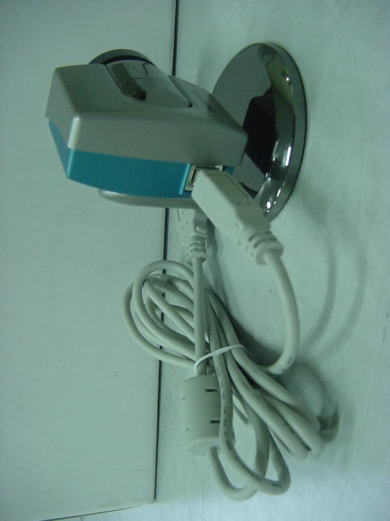
Click to zoom
Application Details
- Equipment Class
- JBP - Part 15 Class B Computing Device Peripheral
- Date of Grant
- Mar 22, 2001
- Application Purpose
- Original Equipment
- Date of Application
- Mar 22, 2001
- Equipment Note
- USB PC Camera
- Company
- Prochips Inc
- Country
- South Korea
Documents & Files
Document Text
Text extracted from the exhibit documents filed with the FCC. Open a document above to read the original.
Users Manual
Content 1. Product composition 2. Before installing 3. Installing CAMERA 4. Function and usage of viewer 4.0 5. Question and Answer Q&A 6. Specification 7. Warranty FCC INFORMATION TO THE USER This equipment has been tested and found to comply with the limits for a Class B digital device, pursuant to part 15 of the FCC Rules. These limits are designed to provide reasonable protection against harmful interference in a residential installation. This equipment generates, uses and can radiate radio frequency energy and, if not installed and used in accordance with the instructions, may cause harmful interference to radio communications. However, there is no guarantee that interference will not occur in a particular installation. If this equipment does cause harmful interference to radio or television reception, which can be determined by turning the equipment off and on, the user is encouraged to try to correct the interference by one more of the following measures: -. Reorient or relocate the receiving antenna. -. Increase the separation between the equipment and receiver. -. Connect the equipment into an outlet on a circuit different from that to which the receiver is connected. -. Consult the dealer or an experienced radio/TV technician for help. WARNING Changes or modifications not expressly approved by the manufacturer could void the user’s authority to operate the equipment. 1. Product Composition Thank you for buying PC CAMERA of PROCHIPS TECHNOLOGY INC. Prochips PC CAMERA is video communication USB CAMERA offering clear image and color. This product supports video communication, video e-mail editing and image processing needed in multimedia function. This product consists of as follows 1-1 * This manual is equally used in PCA-2300, PCA-3100, PCA-3202, PCA-2302, PCA-3302 2. Before installing 1. System specification for installation Pentium* MMX 200MHZ and above (Pentium II CPU is recommended) USB port Windows*98 and above RAM 32MB and above SUPER VGA and above CD-ROM drive Prochips PC CAMERA is able to use in WINDOWS98, WINDOWS98 SE, WINDOWS ME, WINDOWS2000 and execute using DIRECTX. It is recommended that you install DIRECTX 6.0 and above for picture quality and frame rate improvement. ** Reference Information Before installing the Prochips USB PC Camera, you need to check if USB controller is properly installed by selecting My Computer - Control Panel - System - Device Manager. If USB controller is not properly installed, errors can occur when USB related devices are installed. For installing USB controller, please refer to main board manual. Pentium* is trademark of Intel. Windows* is trademark of Microsoft. 3. Installing CAMERA Please take following steps to install Prochips USB Camera. - Driver installation( including Viewer 4.0) - Connection PC CAMERA to USB PORT - Installation completion after detecting new hardware 1. Installation driver and Viewer 4.0 1-1. Please insert provided CD-ROM into CD-ROM drive. after that, installation starts. (Execute “setup.exe” file in CD-ROM if auto-execution is impossible by DIRECT CD of ADAPTEC* inc or other programs) 1-2. After checking the following message, then click “Yes” button 1-3. Proceed the installation by clicking “Next” button 1-3. After clicking “Finish” button, connect PC CAMERA to USB PORT. You can complete installation of PROCHIPS PC CAMERA driver and Viewer 4.0 using this process. 1-4. After installing driver, Please connect PC CAMERA to USB PORT. 3-4 1-5. It detects device automatically after connection * It completes detection in a few seconds, but it is different from system performance and specification. Don’t turn off computer until complete detection. 1-7. Please check if “Prochips Dual Mode USB Camera” or “Prochips Dual Mode USB Camera Plus” is properly installed in “Control Panel - System - Device Manager - Imaging Device”. 2. MGI Video Wave III SE installation MGI Video Wave III SE, Strong Graphic Tool offered by Prochips, provides moving picture and still image editing function. Strong and Easy user interface and help word provided by voice assist user to use comfortably 2-1. To install MGI Video Wave III SE, execute “setup.exe” in VideoWave folder of CD. 2-2. Please proceed continuously to the next steps by clicking “Next” button. 2.3. Video Wave III SE program is made by MGI Software Corp. You must register e-mail address to get a newest inforamtion of MGI. If you need, Please register 2.4. Finally, you can see the installation completion window. If you choose “seeing guide tour “, you can hear from animation and voice. It helps you to use MGI Video Wave III SE. * Windows ME user must install “WinMEPatch.exe” 4. Function and usage of Viewer 4.0 Please execute Start - Program - Prochips - PC CAMERA - Viewer 4.0 to run Viewer 4.0. Function of each buttons in Viewer 4.0 is as follows. Record Stop SnapShot Set Camera Sequence Image E-Mail View Rename Delete Delete All NetMeeting Function usage 1. Still image capturing function In case of clicking still image capturing button which looks like camera, Still image appears in the below box like image clip. Captured file can edit using Windows Paint program automatically linked by double clicking image clip. And, in case of clicking mouse button and Shift or Ctrl key together, you can choose many images. In case of clicking button, you can see the slide show. button can delete chosen files, button delete all images. button store chosen image to other name. 2. Continuously Capturing function Continuously capturing function can use to observe movement of object. It is initially set that every ten seconds capture image file after clicking continuously capturing button. If you want to adjust capturing interval, after clicking button you must change newly continuously capturing item. 3. Moving picture capture If you use recording button, you can make moving picture file, *.AVI. Viewer 4.0 supports two recording completion method as follow. A. Method to complete recording b…
Text truncated - open the document above for the full version.
ID Label/Location Info
FCC ID. : MY8PCA-3302 File No. : E013R-005 ONETECH Testing & Evaluation Lab. IDENTIFICATION LABEL: PROPOSED FCC ID LABEL The label included following statement will be attached on the bottom of product. This device complies with Part 15 of the FCC Rules. Operation is subject to the following two conditions: (1) this device may not cause harmful interference, and (2) this device must accept any interference received, including interference that may cause undesired operations. Made in Korea FCC ID : MY8PCA-3302 FCC ID AREA
Internal Photos
FCC ID.: MY8PCA-3302 File No.: E013R-005 ONETECH Testing & Evaluation Lab. FCC ID.: MY8PCA-3302 File No.: E013R-005 ONETECH Testing & Evaluation Lab. FCC ID.: MY8PCA-3302 File No.: E013R-005 ONETECH Testing & Evaluation Lab. FCC ID.: MY8PCA-3302 File No.: E013R-005 ONETECH Testing & Evaluation Lab. FCC ID.: MY8PCA-3302 File No.: E013R-005 ONETECH Testing & Evaluation Lab.
Test Report
Page 1 of 13 FCC ID. : MY8PCA-3302 File No. : E013R-005 This report shall not be reproduced except in full without our written approval. EMC-004 (Rev.0) HEAD OFFICE : #505 SK APT. Factory 223-28, Sangdaewon 1 Dong, Jungwon-Gu, Seongnam-City, Kyunggi-Do, 462-121, Korea (TEL: 82-31-746-8500 FAX: 82-31-746-8700 ) EMC Testing Dept : 426-1 Daessangryung-Ri, Chowol-Myun, Kwangju-Kun, Kyunggi-Do 464-860 Korea. (TEL: 82-31-765-8289 FAX: 82- 31-766-2904) ONETECH Testing & Evaluation Lab. E LECTROMAGNETIC E MISSION C OMPLIANCE R EPORT Test report file number : E013R-005 Applicant : PROCHIPS TECHNOLOGY INC. Address : 118-2, Oryu-Dong, Guro-Gu, Seoul, 152-102, Korea Manufacturer : PROCHIPS TECHNOLOGY INC. Address : 118-2, Oryu-Dong, Guro-Gu, Seoul, 152-102, Korea Type of Equipment : USB PC CAMERA FCC ID : MY8PCA-3302 Model / Type No. : PCA-3302 Serial number : N/A Total page of Report : 13 pages (including this page) Date of Incoming : February 12, 2001 Date of issuing : March 07, 2001 SUMMARY The equipment complies with the regulation; FCC PART 15 SUBPART B § 15.101 This test report contains only the result of a single test of the sample supplied for the examination. It is not a general valid assessment of the features of the respective products of the mass-production Reviewed by: Approved by: Y. K. Kwon / Chief Engineer S. S. Hong / Managing Director EMC Dept. EMC Dept. ONETECH Corp. ONETECH Corp. Page 2 of 13 FCC ID. : MY8PCA-3302 File No. : E013R-005 This report shall not be reproduced except in full without our written approval. EMC-004 (Rev.0) HEAD OFFICE : #505 SK APT. Factory 223-28, Sangdaewon 1 Dong, Jungwon-Gu, Seongnam-City, Kyunggi-Do, 462-121, Korea (TEL: 82-31-746-8500 FAX: 82-31-746-8700 ) EMC Testing Dept : 426-1 Daessangryung-Ri, Chowol-Myun, Kwangju-Kun, Kyunggi-Do 464-860 Korea. (TEL: 82-31-765-8289 FAX: 82- 31-766-2904) ONETECH Testing & Evaluation Lab. Page 3 of 13 FCC ID. : MY8PCA-3302 File No. : E013R-005 This report shall not be reproduced except in full without our written approval. EMC-004 (Rev.0) HEAD OFFICE : #505 SK APT. Factory 223-28, Sangdaewon 1 Dong, Jungwon-Gu, Seongnam-City, Kyunggi-Do, 462-121, Korea (TEL: 82-31-746-8500 FAX: 82-31-746-8700 ) EMC Testing Dept : 426-1 Daessangryung-Ri, Chowol-Myun, Kwangju-Kun, Kyunggi-Do 464-860 Korea. (TEL: 82-31-765-8289 FAX: 82- 31-766-2904) ONETECH Testing & Evaluation Lab. CONTENTS Page 1. VERIFICATION OF COMPLIANCE ...............................................................................................................................4 2. GENERAL INFORMATION .................................................................................................................................................5 2.1 P RODUCT D ESCRIPTION ............................................................................................................................................................5 2.2 R ELATED S UBMITTAL ( S ) / G RANT ( S ).................................................................................................................................5 2.3 T EST S YSTEM D ETAILS ..............................................................................................................................................................6 2.4 T EST M ETHODOLOGY .................................................................................................................................................................6 2.5 T EST F ACILITY ..............................................................................................................................................................................6 3. SYSTEM TEST CONFIGURATION .................................................................................................................................7 3.1 J USTIFICATION ..............................................................................................................................................................................7 3.2 EUT EXERCISE S OFTWARE ......................................................................................................................................................7 3.3 C ABLE D ESCRIPTION ..................................................................................................................................................................7 3.4 N OISE S UPPRESSION P ARTS ON C ABLE ...............................................................................................................................8 3.5 E QUIPMENT M ODIFICATIONS .................................................................................................................................................8 3.6 C ONFIGURATION OF T EST S YSTEM .......................................................................................................................................8 4. PRELIMINARY TEST ...............................................................................................................................................................9 4.1 AC P OWER LINE C ONDUCTED E MISSION T EST ...............................................................................................................9 4.2 R ADIATED E MISSION T EST ......................................................................................................................................................9 5. FINAL RESULT OF MEASURMENT .........................................................................................................................10 5.1 C ONDUCTED E MISSION T EST ................................................................................................................................................10 5.2 R ADIATED E MISSION T EST ....................................................................................................................................................12 6. FIELD STRENGTH CALCULATION ...........................................…
Text truncated - open the document above for the full version.
Test Setup Photos
FCC ID. : MY8PCA-3302 File No. : E013R-005 ONETECH Testing & Evaluation Lab. FCC ID. : MY8PCA-3302 File No. : E013R-005 ONETECH Testing & Evaluation Lab.
Contact Information
Applicant
Se-Eak Oh(Manager)
Test Firm
ONETECH Corp.Y. Kwon
Technical Specifications
| # | Rule Parts | Frequency Range | Power Output |
|---|---|---|---|
| 1 | 15B | - | - |
Other Applications from Prochips Inc
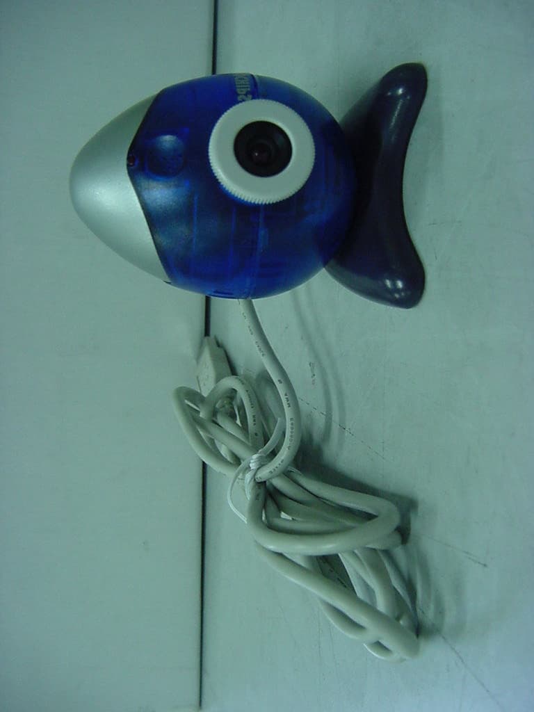
MY8PCA-2302
Mar 19, 2001USB PC Camera
Equipment Class
JBP - Part 15 Class B Computing Device Peripheral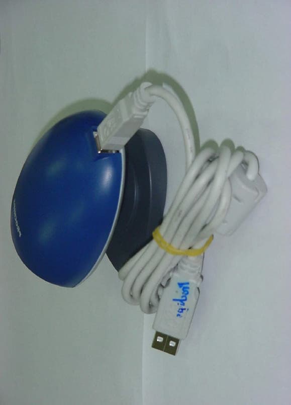
MY8PCA-3100
Nov 14, 2000USB PC CAMERA
Equipment Class
JBP - Part 15 Class B Computing Device Peripheral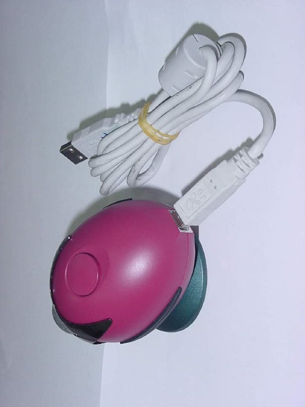
MY8PCA-3202
Nov 14, 2000USB PC CAMERA
Equipment Class
JBP - Part 15 Class B Computing Device PeripheralMY8DREAMVIEWTOV64
Jul 21, 1996Multimedia Card Maximum resolution: 1600 X 1200 I
Equipment Class
JBP - Part 15 Class B Computing Device Peripheral