MYF-H9PLA4121Fixed Wireless Spread Spectrum System
L-Com, Inc.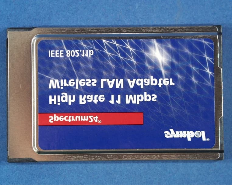
Click to zoom
Application Details
- Equipment Class
- DSS - Part 15 Spread Spectrum Transmitter
- Date of Grant
- Sep 05, 2001
- Application Purpose
- Original Equipment
- Date of Application
- Sep 05, 2001
- Equipment Note
- Fixed Wireless Spread Spectrum System
- Frequency Range
- 2412.00000000 - 2462.00000000
- Company
- L-Com, Inc.
- Country
- United States
Documents & Files
Document Text
Text extracted from the exhibit documents filed with the FCC. Open a document above to read the original.
Users Manual
Re: Certification for Hyperlink IN2401 Radio Model: IN2401 FCC ID: MYF-H9PLA4121 CANADA: to be provided by IC USER'S MANUAL INFORMATION (PRELIMINARY) The User's Manual is in preparation. The following material will be contained in the manual: FCC ID: MYF-H9PLA4121 CANADA: to be provided by IC This device complies with Part 15 of the FCC Rules and with RSS-210 of Industry Canada. Operation is subject to the following two conditions: (1) This device may not cause harmful interference, and (2) This device must accept any interference received, including interference that may cause undesired operation. WARNING: Changes or modifications not expressively approved by the party responsible for compliance could void the user's authority to operate the equipment. Hyperlink / Intel PRO – Extended-Range Professional Antenna Systems 1 Hyperlink / Intel PRO Wireless Professional Extended-Range Antenna Kits Featuring Intel Spread Spectrum Radio Technology Installation Manual NOTE: The antenna system shall be installed ONLY by experienced antenna installers who are familiar with local building and safety codes, and wherever necessary have been licensed by appropriate government regulatory bodies. Failure to do so may void the Product Warranty, as well as expose the end-user to legal and/or financial liabilities. Hyperlink Technologies, its agents, resellers or distributors, are not liable for injury, damage, or violation of government regulations that may arise from failing to comply with the guidelines described in this document. Hyperlink / Intel PRO – Extended-Range Professional Antenna Systems 2 Disclaimer: The diagrams used in this manual are for illustrative purposes only. They should not be confused with the Intel end-user installed antenna options. When these diagrams are used the transceiver will be installed in conjunction with the specific Professionally-Installed Antenna Kits including DC Injector/Lightning Protector, Amplifier, cables and antennas listed in this manual. Copyright © 2001, Hyperlink Technologies, Inc.. All rights reserved. No part of the contents of this document may be transmitted or reproduced in any form or by any means without the written permission of Hyperlink Technologies, Inc. HyperGain and HyperAmp are trademarks or registered trademarks of Hyperlink Technologies, Inc. in the United States and/or other countries. Hyperlink / Intel PRO – Extended-Range Professional Antenna Systems 3 USA- Federal Communications Commission (FCC) Interference Statement This device complies with Part 15 of the FCC Rules. Operation is subject to the following two conditions: (1) this device may not cause harmful interference, and (2) this device must accept any interference received, including interference that may cause undesired operation. Information to the user NOTE: This equipment has been tested and found to comply with the limits for a Class B digital device, pursuant to Part 15 of the FCC Rules. These limits are designed to provide reasonable protection against harmful interference in a residential installation. This equipment generates, uses, and can radiate radio frequency energy. If not installed and used in accordance with the instructions, it may cause harmful interference to radio communications. However, there is no guarantee that interference will not occur in a particular installation. If this equipment does cause harmful interference to radio or television reception, which can be determined by turning the equipment off and on, the user is encouraged to try and correct the interference by one or more of the following measures: • Reorient or relocate the receiving antenna. • Increase the distance between the equipment and the receiver. • Connect the equipment to an outlet on a circuit different from that to which the receiver is connected. • Consult the dealer or an experienced radio/TV technician for help. Any changes or modifications of equipment not expressly approved by the manufacturer could void the user’s authority to operate the equipment and the company’s warranty. NOTE: The antenna system shall be installed ONLY by experienced antenna installers who are familiar with local building and safety codes, and wherever necessary have been licensed by appropriate government regulatory bodies. Failure to do so may void the Product Warranty, as well as expose the end-user to legal and/or financial liabilities. Hyperlink Technologies, its agents, resellers or distributors, are not liable for injury, damage, or violation of government regulations that may arise from failing to comply with the guidelines described in this document. Hyperlink / Intel PRO – Extended-Range Professional Antenna Systems 4 Caution: Exposure to Radio Frequency Radiation. The radiated output power of this product is below the FCC radio exposure limits. Nevertheless, this product shall be used in such a manner that the potential for human contact during normal operation is minimized. Antenna shall be mounted in such a manner as to minimize the potential for human contact during normal operation. In order to avoid the possibility of exceeding the FCC radio frequency exposure limits, human proximity to the antenna shall not be less than 71 cm during normal operation. Hyperlink Technologies is not responsible for any radio or television interference caused by unauthorized modification of this device or the substitution or attachment of connecting cables and equipment other than specified by Hyperlink Technologies. The correction of interference caused by such unauthorized modification, substitution or attachment will be the responsibility of the user. Antenna System Specified Antenna Gain (dBi) Maximum Output Power at Antenna Terminal (dBm) Total EIRP (dBm) Minimum RF Exposure Separation Distance (cm) HG2408U 8.0 16.0 24.0 4.5 HG2410U 10.0 16.0 26.0 5.6 HG2415U 15.0 16.0 31.0 10 HG2408P 8.0 16.0 24.0 4.5 HG2409P 8.0 16.0 24.0 5.0 HG2412P 12.0 16.0 28.0 7.1 HG2414P 14.0 16.0 30.0 8.9 HG2415Y 14.5 16.0 30.5…
Text truncated - open the document above for the full version.
Cover Letter(s)
Re: Certification for Hyperlink IN2401 Radio Model: IN2401 FCC ID: MYF-H9PLA4121 CANADA: to be provided by IC POWER OF ATTORNEY A letter granting Valdis V. Liepa the Power of Attorney is on file and can be provided when so requested. Re: Certification for Hyperlink IN2401 Radio Model: IN2401 FCC ID: MYF-H9PLA4121 CANADA: to be provided by IC REQUEST FOR CONFIDENTIALITY Pursuant to 47 CRF 0.459, Hyperlink requests that a part of the subject application be held confidential. This comprises Exhibits (5) Schematics (10) Parts List (Part of Exhibit only) Hyperlink has spent substantial effort in developing this product and it is one of the first of its kind in industry. Having the subject information easily available to "competition" would negate the advantage they have achieved by developing this product. Not protecting the details of the design will definitely result in a financial hardship. If there are any questions regarding this request, please contact me at the above address or call 734-483-4211, fax 734-647-2106 or e-mail [email protected]. Sincerely, Valdis V. Liepa Research Scientist University of Michigan August 16, 2001 Re: Certification for Hyperlink IN2401 Radio Model: IN2401 FCC ID: MYF-H9PLA4121 CANADA: to be provided by IC STATEMENT OF MODIFICATIONS During the course of testing, amplifier (if need), filter (if need), and antenna were selected, and then the available channels for the particular configuration were reduced (if needed) to meet the band-edge and harmonic emission limits. (Also see Section 3.1 of the attached Test Report). _____________________ Valdis V. Liepa Research Scientist Re: Certification for Hyperlink IN2401 Radio Model: IN2401 FCC ID: MYF-H9PLA4121 CANADA: to be provided by IC GENERAL PRODUCT INFORMATION The device, for which certification is pursued, has been designed by: Hyperlink Technologies Inc 1200 Clint Moore Road, Suite 14 Boca Raton, Florida 33487 Peter Roth Tel: (561) 995-2256 Fax: (561) 995-2432 It will be manufactured by: Hyperlink Technologies Inc 1200 Clint Moore Road, Suite 14 Boca Raton, Florida 33487 Peter Roth Tel: (561) 995-2256 Fax: (561) 995-2432 It will be marketed and serviced by: Hyperlink Technologies Inc
Cover Letter(s)
August 15, 2001 Federal Communications Commission Equipment Approval Services P.O. Box 358315 Pittsburgh, PA 15251-5315 Re: Certification for Hyperlink IN2401 Radio Model: IN2401 FCC ID: MYF-H9PLA4121 CANADA: to be provided by IC Please find enclosed application materials for certification of Hyperlink IN2401 Radio. We tested it and found it to comply with Part 15. If there are any questions regarding the application or testing performed, please contact me at the above address or call 734-483-4211, fax 734-647-2106, or e-mail [email protected]. Sincerely, Valdis V. Liepa Research Scientist Enclosures: Industry Canada Cover Letter Table of Contents for Exhibits August 15, 2001 Certification and Engineering Bureau Industry Canada 3701 Carling Avenue, Bldg. 94 Ottawa, Ontario K2H 8S2 Re: Certification for Hyperlink IN2401 Radio Model: IN2401 FCC ID: MYF-H9PLA4121 CANADA: to be provided by IC Please find enclosed application materials for certification of Hyperlink IN2401 Radio. We tested the device and found it to comply with RSS-210. The product is identified by: Model: IN2401 If there are any questions, suggestions, etc., regarding the application or testing performed, please contact me at the above address or call 734-483-4211, fax 734-647- 2106; e-mail: [email protected]. Sincerely, Valdis V. Liepa Research Scientist Enclosures: Application Form with payment (This) Letter of Transmittal Summary of Test Results Table of Contents for Exhibits Application Forms and Exhibits (on CD ROM) August 16, 2001 Re: Certification for Hyperlink IN2401 Radio Model: IN2401 FCC ID: MYF-H9PLA4121 CANADA: to be provided by IC TABLE OF CONTENTS FOR EXHIBITS Total Pages (1) ID Label/Location Information 2 (2) Attestation Statements 7 (3) External Photos 14 (4) Block Diagrams 2 (5) Schematics 3 (6) Test Report 56 (7) Test Setup Photos 1 (8) User’s Manual 17 (9) Internal Photos 8 (10) Parts List/Parts Placement 9 (11) RF Exposure Information 1 (12) Operational Description 1 (13) Cover Letter(s) 3
External Photos
HyperLink Antenna, Model HG2403MU HyperLink Antenna, Model HG2405MU HyperLink Antenna, Model HG2408U HyperLink Antenna, Model HG2408P HyperLink Antenna, Model HG2409P HyperLink Antenna, Model HG2410U HyperLink Antenna, Model HG2414P HyperLink Antenna, Model HG2415U HyperLink Antenna, Model HG2415Y HyperLink Antenna, Model HG2415P HyperLink Antenna, Model HG2415G HyperLink Antenna, Model HG2417P HyperLink Antenna, Model HG2419G HyperLink Antenna, Model HG2420P HyperLink Antenna, Model HG2424G HyperLink AGC Amplifier (Top) HyperLink AGC Amplifier (Bottom) HyperLink Power Injector (Top) HyperLink Power Injector (Bottom) Network Systems Organization FCC Certification Report for the LA4121 WLAN PC Card FCC ID: H9PLA4121 EXHIBIT 3 EXTERNAL PHOTOGRAPHS
ID Label/Location Info
FCC ID Label MYF-H9PLA4121 FCC ID: MYF-H9PLA4121 CANADA: XXXXXX This device complies with Part 15 of FCC Rules. Operation is subject to the following conditions: (1) This device may not cause harmful interference and (2) this device must accept any interference that may cause undesired operation.
Internal Photos
H9PLA4121 H9PLA4121 H9PLA4121 H9PLA4121 H9PLA4121 H9PLA4121
Operational Description
Hyperlink 2.4 GHz Bi-Directional Amplifier With AGC The Hyperlink bi-directional amplifier utilizes Automatic Gain Control, AGC, to compensate for cable length differences encountered during installation. The amplifier uses a variation of AGC called Forward AGC, FAGC, to control the gain of the transmit path so as to provide a constant amplifier power output. FAGC is a well known technique utilized in many professional and consumer products to normalize signal levels. The amplifier uses it’s input RF pulse detector to provide a DC level proportional to the amplitude of the RF pulse. This DC pulse is fed to a high speed differential amplifier, which in turn drives a Voltage Controlled Attenuator, VCA, in the transmit signal path. The VCA adjusts the transmit power on a burst to burst basis, so as to provide a constant amplifier output power even if the RF bursts vary in amplitude. The RF detector and VCA are both linearized over a 20 dB range. This allows the input level to vary over 20 dB in level, and the output power will stay constant.
Operational Description
HyperLink FCC ID: MYF-H9PLA4121 System Configuration and EIRP Information System Antenna Cables Filter Amplifier 03MU1 HG2403MU 10ft (attached to antenna) Black (4 pole) 1 W NON-AGC 03MU HG2403MU 10ft (attached to antenna) None 250 mW AGC 05MU1 HG2405MU 10ft (attached to antenna) Black (4 pole) 1 W NON-AGC 05MU HG2405MU 10ft (attached to antenna) None 250 mW AGC 08P HG2408P 50 ft None None 08PA HG2408P 50 ft None 100 mW AGC 08U HG2408U 50 ft None None 08UA HG2408U 50 ft None 100 mW AGC 09P HG2409P 50 ft None None 09PA HG2409P 50 ft None 100 mW AGC 10U HG2410U 50 ft None None 10UA HG2410UA 50 ft None 100 mW AGC 12P HG2412P 50 ft None None 14P HG2414P 50 ft None None 14PA HG2414P 50 ft None 100 mW AGC 15G HG2415G 50 ft None None 15P HG2415P 50 ft None None 15U HG2415U 50 ft None None 15UA HG2415U 50 ft None 100 mW AGC 15Y HG2415Y 50 ft None None 15YA HG2415Y 50 ft None 100 mW AGC 17P HG2417P 50 ft None None 19GA HG2419G 50 ft Black (4 pole) 250 mW AGC 20P HG2420P 50 ft None None 24G HG2424G 100 ft None None 24G HG2424G 50 ft Black (4 pole) 250 mW AGC
RF Exposure Info
RF Exposure Limits The following table summarizes the minimum operating distance for each antenna/amplifier system, as calculated from FCC OET Bulletin 65. Potential Health Hazard Radiation Level Ant. Ant. Gain (dB) Po (mW) EIRP (mW) R (cm) Corr. Data Table 03MU 3 1000 1995 12.6 5.1 03MU 3 250 499 6.3 5.2 05MU 5 1000 3162 15.9 5.3 05MU 5 250 791 7.9 5.4 08P 8 40 252 4.5 5.5 08P 8 100 631 7.1 5.6 08U 8 40 252 4.5 5.7 08U 8 100 631 7.1 5.8 09P 9 40 318 5.0 5.9 09P 9 100 794 8.0 5.10 10U 10 40 400 5.6 5.11 10U 10 100 1000 8.9 5.12 12P 12 40 634 7.1 5.13 14P 14 40 1005 8.9 5.14 14P 14 100 2512 14.1 5.15 15G 15 40 1265 10.0 5.16 15P 15 40 1265 10.0 5.17 15U 15 40 1265 10.0 5.18 15U 15 100 3162 15.9 5.19 15Y 14 40 1005 8.9 5.20 15Y 14 100 2512 14.1 5.21 17P 17 40 2005 12.6 5.22 19G 19 250 19858 39.8 5.23 20P 20 40 4000 17.8 5.24 24G 24 40 10048 28.3 5.25 24G 24 250 62797 70.7 5.26 The following equations were used in calculating the operating distance (R). 10 )( 10)()( dBGain mWPomWEIRP⋅= and )/(4 )( 2 cmmWS mWEIRP R ⋅Π⋅ =, S = 1mW/cm 2
Test Report
0 The University of Michigan Radiation Laboratory 3228 EECS Building Ann Arbor, MI 48109-2122 Tel: (734) 764-0500 Measured Radio Frequency Emissions From Hyperlink/Intel Long Range Radio Model IN2401 Report No. 415031-086 August 16, 2001 Copyright © 2001 For: Hyperlink Technologies Inc. 1200 Clint Moore Rd., Suite 14 Boca Raton, FL 33487 Contact: Peter Roth Tel: (561) 995-2256 Fax: (561) 995-2432 PO: verbal Tests supervised by: Measurements made by: Report approved by: ____________________ Joseph Brunett Valdis V. Liepa Valdis Liepa Research Scientist ______________________________________________________________________________ Summary Tests for compliance with FCC Regulations, according to Part 15 (15.247), and with Industry Canada Regulations, RSS-210 (Issue 5, Draft 1, Section 6.2.2 (o)) were performed on HyperLink spread spectrum RF Extended Range LAN System. The DUT is subject to the Rules and Regulations as a transmitter, a receiver, and a digital device. This link uses an already FCC certified spread spectrum Intel radio, but adds high gain antennas, amplifiers, filters, and cables. Here we report on measurements as required for combinations of antennas, filters, and amplifiers. In testing performed May 19-25, 2001, of the twenty-six combinations tested, the radiated emissions in restricted bands were met by 0.1 dB (see pp. 19, 26). 1 Table of Contents 1. Introduction..............................................................................................................................3 2. Test Procedure and Equipment Used.........................................................................................3 3. Configuration and Identification of Device Under Test................................................................4 3.1 EMI Relevant Modifications..............................................................................................5 4. Emission Limits.........................................................................................................................6 4.1 Radiated Emission Limits...................................................................................................6 4.2 Conductive Emission Limits...............................................................................................7 5. Radiated Emission Tests and Results..........................................................................................7 5.1 Anechoic Chamber Measurements....................................................................................7 5.2 Outdoor Measurements.....................................................................................................7 5.3 Computations and Results..................................................................................................7 5.4 Duty Factor for Normal Operation.....................................................................................8 6. Other Measurements and Computations.....................................................................................8 6.1 Peak-to-Average Ratio (15.35(b))......................................................................................8 6.2 Potential Health Hazard EM Radiation Level......................................................................8 6.3 Peak and Average Output Power (15.247(b)).....................................................................9 6.4 Power Line Conducted Emissions (15.270).........................................................................9 6.5 Bandwidth (15.247(a)(2))..................................................................................................9 6.6 RF Antenna Conducted Spurious Emissions (15.247(c))....................................................10 6.7 Power Spectral Density and Line Spacing (15.247(d)).......................................................10 6.8 AGC Performance of the RF Amplifier............................................................................11 Table 2.1 Test Equipment..................................................................................................................3 Figure 3.1 Basic block diagram of the system.....................................................................................5 Table 4.1 Radiated Emission Limits (FCC:15.205; IC:RSS-210, 6.3) - Transmitter.................................6 Table 4.2 Radiated Emission Limits (FCC:15.109;IC: RSS-210, 7.3) - Digital device..............................6 Table 4.3 Conducted Emission Limits (FCC:15.107; IC: RSS-210, 6.6).................................................7 Table 6.1 Potential Health Hazard Radiation Level..............................................................................8 Table 6.1 Peak and Average Output Power (Antenna Conducted)......................................................9 Figure 6.1-1. Diagram of AGC Amplifier Test Setup........................................................................11 Figure 6.1-2. Plot of Peak Output Power vs. Cable Attenuation........................................................11 Table 5.1 Highest Radiated Emissions..............................................................................................12 Table 5.2 Highest Radiated Emissions..............................................................................................13 Table 5.3 Highest Radiated Emissions..............................................................................................14 Table 5.4 Highest Radiated Emissions..............................................................................................15 Table 5.5 Highest Radiated Emissions..............................................................................................16 Table 5.6 Highest Radiated Emissions..............................................................................................17 Table 5.7 Highest Radiated Emissions.....................................................................…
Text truncated - open the document above for the full version.
Test Report
A1365 Adams Ct. Menlo Park, CA 94025 Symbol Technologies, Model No. LA4121Date of Test: April 3 & 7, 2000 FCC ID: File: J20008658dVersion 1.0Page 1 of 25 Table of Contents 1.0Summary of Tests.................................................................................................................................2 2.0General Description.............................................................................................................................3 2.1Product Description..................................................................................................................3 2.2Related Submittal(s) Grants.....................................................................................................3 2.3Test Methodology.....................................................................................................................4 2.4Test Facility...............................................................................................................................4 3.0System Test Configuration..................................................................................................................5 3.1Support Equipment and description.........................................................................................5 4.2Block Diagram of Test Setup...................................................................................................5 3.3Justification...............................................................................................................................6 3.4Software Exercise Program.......................................................................................................6 3.5Mode of Operation During Test...............................................................................................6 3.6Modifications Required for Compliance..................................................................................6 3.7Additions, deviations and exclusions from standards..............................................................6 4.0Measurement Results...........................................................................................................................7 4.1Maximum Conducted Output Power at Antenna Terminals....................................................7 4.2Minimum 6 dB RF Bandwidth................................................................................................8 4.3Maximum Power Density Reading...........................................................................................9 4.4Out of Band Conducted Emissions.........................................................................................10 4.5Out of Band Radiated Emissions............................................................................................11 4.7AC Line Conducted Emission.................................................................................................13 4.8Radiated Emissions from Digital Section of Transceiver (Transmitter)................................14 4.9Radiated Emissions from Receiver Section of Transceiver (L.O. Radiation)........................15 4.10Processing Gain Measurements..............................................................................................16 4.11Transmitter Duty Cycle Calculation and Measurements........................................................17 5.0Appendix A : Plots..............................................................................................................................18 6.0Appendix B: Photographs................................................................................................................19 A1365 Adams Ct. Menlo Park, CA 94025 Symbol Technologies, Model No. LA4121Date of Test: April 3 & 7, 2000 FCC ID: File: J20008658dVersion 1.0Page 3 of 25 2.0General Description 2.1Product Description The Symbol Technologies model LA4121 is 2.4 GHz Spread Spectrum radio in the form of a PCMCIA card that is used for wireless communication from a computer to a LAN. A pre-production version of the sample was received on January 31, 2000 in good condition. Overview of LA4121 ApplicantSymbol Technologies Trade Name & Model No.Symbol Technologies / LA4121 FCC IdentifierNot Labeled Use of Product Manufacturer & Model of Spread Spectrum Module Symbol Technologies Type of TransmissionDirect Sequence Rated RF Output (mW)22 dBm Frequency Range (MHz)2412 – 2462 MHz Number of Channel(s)11 Antenna(s) & Gain, dBi9 Processing Gain Measurements[ ]Will be provided to ITS for submission with the application [ ]Will be provided directly to the FCC reviewing engineer by the client or manufacturer of the spread spectrum module Antenna Requirement[ ]The EUT uses a permanently connected antenna. [X]The antenna is affixed to the EUT using a unique connector which allows for replacement of a broken antenna, but DOES NOT use a standard antenna jack or electrical connector. [ ]The EUT requires professional installation (attach supporting documentation if using this option). Manufacturer name & address Symbol Technologies 2145 Hamilton Avenue San Jose CA 95125 2.2Related Submittal(s) Grants None A1365 Adams Ct. Menlo Park, CA 94025 Symbol Technologies, Model No. LA4121Date of Test: April 3 & 7, 2000 FCC ID: File: J20008658dVersion 1.0Page 4 of 25 2.3Test Methodology Both AC mains line-conducted and radiated emissions measurements were performed according to the procedures in ANSI C63.4 (1992). Radiated tests were performed at an antenna to EUT distance of 3 meters, unless stated otherwise in the "Data Sheet" of this Application. All other measurements were made in accordance with the procedures in part 2 of CFR 47. 2.4Test Facility The open area test site and conducted measurement facility used to collect the radiated data is site 2. This test facility and site measurement data have been fully placed on file with the FCC and NVLAP accredited. A1365 Adams Ct. Menlo Park, CA 94025 Sym…
Text truncated - open the document above for the full version.
Test Setup Photos
Radiated Test Setup
Contact Information
Applicant
Kenneth Burgner(Product Manager)
Technical Contact
University of Michigan/EECSValdis V Liepa
[email protected]734 483 4211
1301 Beal Avenue · Ann Arbor, Michigan · United States
Test Firm
University of MichiganValdis Liepa
Technical Specifications
| # | Rule Parts | Frequency Range | Power Output |
|---|---|---|---|
| 1 | 15C | 2.41 GHz - 2.46 GHz | 1 W |
Other Applications from L-Com, Inc.
MYF-LCUSB2415
Aug 17, 20142.4 GHz 802.11n Wireless USB Adapter
Equipment Class
DTS - Digital Transmission System
MYF-LCUSB
Apr 26, 2010802.11b/g USB Dongle with Amplifier
Equipment Class
DTS - Digital Transmission System
MYF-LCUSBX
Apr 15, 2010802.11b/g USB Dongle with Amplifier
Equipment Class
DTS - Digital Transmission System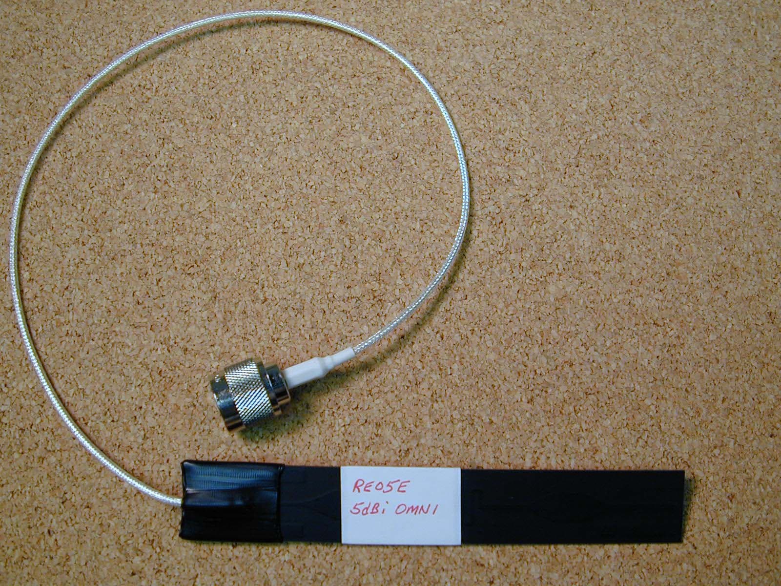
MYF-XI-325
May 25, 2004Spread Spectrum Transmission System
Equipment Class
DTS - Digital Transmission System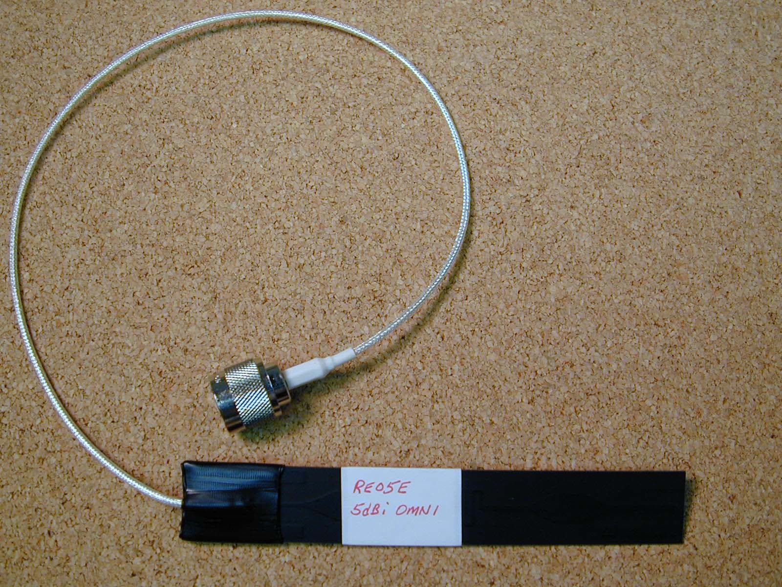
MYF-XI-325X
May 16, 2004Spread Spectrum Transmission System
Equipment Class
DTS - Digital Transmission System