MYF-XI-325XSpread Spectrum Transmission System
L-Com, Inc.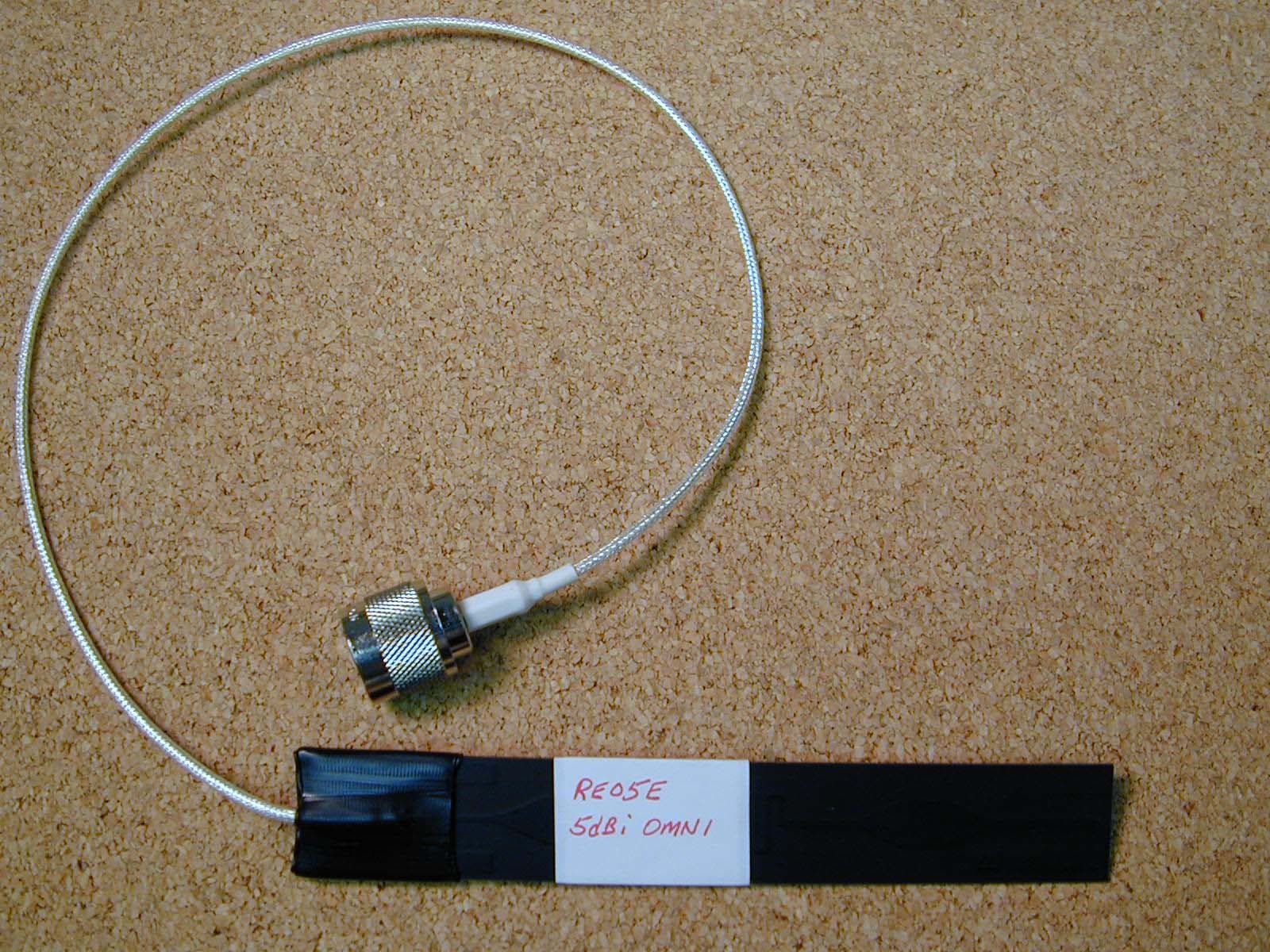
Click to zoom
Application Details
- Equipment Class
- DTS - Digital Transmission System
- Date of Grant
- May 16, 2004
- Application Purpose
- Original Equipment
- Date of Application
- May 16, 2004
- Equipment Note
- Spread Spectrum Transmission System
- Frequency Range
- 2412.00000000 - 2462.00000000
- Company
- L-Com, Inc.
- Country
- United States
Documents & Files
Document Text
Text extracted from the exhibit documents filed with the FCC. Open a document above to read the original.
Users Manual
End-User Manual Model HA2401-XI-325X FCC ID: MYF-XI-325X IC: 2837A- XI-325X Interference Statement This device complies with Part 15 of the FCC Rules and with RSS-210 of Industry Canada. Operation is subject to the following two conditions: (1) this device may not cause harmful interference, and (2) this device must accept any interference received, including interference that may cause undesired operation. Warning: Changes or modifications not expressively approved by the party responsible for compliance could void the user’s authority to operate the equipment. The term “IC:” before the radio certification number only signifies that Industry Canada technical specifications were met. Information to the user NOTE: This equipment has been tested and found to comply with the limits for a Class B digital device, pursuant to Part 15 of the FCC Rules. These limits are designed to provide reasonable protection against harmful interference in a residential installation. This equipment generates, uses, and can radiate radio frequency energy. If not installed and used in accordance with the instructions, it may cause harmful interference to radio communications. However, there is no guarantee that interference will not occur in a particular installation. If this equipment does cause harmful interference to radio or television reception, which can be determined by turning the equipment off and on, the user is encouraged to try and correct the interference by one or more of the following measures: Reorient or relocate the receiving antenna. Increase the distance between the equipment and the receiver. Connect the equipment to an outlet on a circuit different from that to which the receiver is connected. Consult the dealer or an experienced radio/TV technician for help. Any changes or modifications of equipment not expressly approved by the manufacturer could void the user’s authority to operate the equipment and the company’s warranty. The device and its antenna and must not be co-located or operating in conjunction with any other antenna or transmitter. When this device is installed either as a fixed-mount or mobile application there is a minimum required separation distance of 20 cm from users. For further information contact: Hyperlink Technologies, Inc. Technical Support Department 1201 Clint Moore Road Boca Raton, FL 33487 Email: [email protected] When locating the antenna or operating this device you must observe the following exposure limits: When this device is installed either as a fixed-mount or mobile application there is a minimum required separation distance of 20 cm from users. Non-Amplified Systems: For non-amplified systems simply plug the antenna connector into the antenna port on the PC card and proceed to PC Card and Software Installation on the next page. Amplified Systems: Amplifier connections are clearly labeled on the amplifier unit as shown below. 1. Connect the antenna to the amplifier output labeled “ANTENNA”. 2. Connect the PC Card to the Amplifier input labeled “RADIO” using the pigtail cable. 3. Plug the AC adapter into the amplifier’s DC power jack and wall outlet. Proceed to PC Card and Software Installation on the next page. PC Card and Software Installation I. Network Configuration XI-325 is anIEEE802.11b-compliant PCMCIA Type II DSSS wireless LAN PC card. It fully supports wireless networking under Windows 95/98/2000/XP and NT 4.0. XI-325 can be operated in Ad-Hoc and Infrastructure network configurations. Ad-Hoc mode allows XI-325 users to join an Basic Service Set (i.e., peer-to-peer mode, without access point). Infrastructure modeallows XI-325 users to join a Extended Basic Service Set (i.e., connect to access point) II. Package Content XI-325 11Mb PC Card CD-ROM Utility Disk Amplifier Kit (Optional) Antenna III. XI-325 and Utility Installation under Windows 1. Insert the XI-325 card into the PCMCIA slot, then start Windows. Windows will auto-detect new hardware and Windows Wizard will display “New Hardware Found". 2. Click on ‘Next’, then insert the corresponding driver and utility CD-ROM into the CD-ROM drive, or the driver and utility disk into the floppy drive.Click on ‘Next’. 3. Once[Insert Win 95/98/2000/XP CD-Rom into the appropriate drive, then click ‘OK’]window appears, please follow by either inserting the Windows CD-Rom or finding the Windows source path within the appropriate drives, then click ‘OK’. 4. Click ‘Finish’ to complete the installation .Restart Windows. 5. To install the XI-325 Utility, insert the XI-325 driver and utility disk once again, then executeA: setup.exe. 6. Follow the on-screen instructions to complete utility installation, then afterward double-click on Infrastructure Network Ad-hoc Network Wired Network Wireless Network Access Point the Utility icon. Utility interface will then appear and configuration can be accomplished here. IV. Using Utility to Set Up Ad-Hoc Network If wireless LAN has already been set up, simply plug in XI-325.Otherwise, set up a wireless network by taking the following steps: 1. On the main utility interface, click on[Diagnostic tools], then click on[Site Survey]. This would disable wireless network links temporarily and display channel quality. Please note that the blue bars indicate the best quality channels. Note that amplified kits are shipped factory set to channel 6 and can not be changed. 2. Back on the main utility interface, click on[Network Configuration] and “Configure the Adapter” window will appear. Setup procedures are as follows: 1) ESSID denotes the assigned name for the designated wireless LAN. If ESSID differs, then wireless connection between wireless end devices will not be accomplished. Please note that selecting[Use Non-Specified ESSID: ANY] will possibly be connected to other wireless LAN. Therefore, ESSID setup is highly recommended. Example: Specify ESSID as : TEST001. Notice: Once the ESSID is set on the initial XI-325, and while the rest of the ESSID remains as defaul…
Text truncated - open the document above for the full version.
Users Manual
User Manual Model HA2401-XI-325X FCC ID: MYF-XI-325X IC: 2837A- XI-325X Interference Statement This device complies with Part 15 of the FCC Rules and with RSS-210 of Industry Canada. Operation is subject to the following two conditions: (1) this device may not cause harmful interference, and (2) this device must accept any interference received, including interference that may cause undesired operation. Warning: Changes or modifications not expressively approved by the party responsible for compliance could void the user’s authority to operate the equipment. The term “IC:” before the radio certification number only signifies that Industry Canada technical specifications were met. NOTE: This system must be installed by experienced professional installers who are familiar with radio frequency (RF) equipment operation as well as local building and safety codes. Failure to do so may void the Product Warranty, as well as expose the end- user to legal and/or financial liabilities. Information to the user NOTE: This equipment has been tested and found to comply with the limits for a Class B digital device, pursuant to Part 15 of the FCC Rules. These limits are designed to provide reasonable protection against harmful interference in a residential installation. This equipment generates, uses, and can radiate radio frequency energy. If not installed and used in accordance with the instructions, it may cause harmful interference to radio communications. However, there is no guarantee that interference will not occur in a particular installation. If this equipment does cause harmful interference to radio or television reception, which can be determined by turning the equipment off and on, the user is encouraged to try and correct the interference by one or more of the following measures: Reorient or relocate the receiving antenna. Increase the distance between the equipment and the receiver. Connect the equipment to an outlet on a circuit different from that to which the receiver is connected. Consult the dealer or an experienced radio/TV technician for help. Any changes or modifications of equipment not expressly approved by the manufacturer could void the user’s authority to operate the equipment and the company’s warranty. NOTE: Certain high gain antennas are intended for point-to-point or point-to- multipoint applications only. These antennas are clearly identified in the table contained in this manual. Note that +36 dBi may only be exceeded for point-to- point applications as given in 15.247(b). It is the installers responsibility that when using these antennas to ensure that the system is used exclusively for point-to-point operations, and that the antenna may not be co-located with other intentional radiators transmitting the same information". The device and its antenna and must not be co-located or operating in conjunction with any other antenna or transmitter. The table contained in this manual identifies which antennas are considered “fixed” and which are “mobile”. When this device is installed as a fixed-mount application there is a minimum required separation distance of 100 cm between the antenna and all persons during normal operation. All mobile antennas must be mounted at a minimum distance of 20 cm from users. Router Installation: Conduct a Site Survey to determine the best location for the system. Once located, install the Router in an appropriate location. Follow the Router mounting instructions for specific mounting details. Open the access cover by depressing the two tabs. Slide the PC Card into the PC Card Slot and plug in the pigtail cable as shown. Then replace the access cover: Connect the Pigtail Cable between the PC Card and the Amplifier/DC Injector input. Install the Antenna NOTE: The antenna system shall be installed ONLY by experienced antenna installers who are familiar with local building and safety codes, and wherever necessary have been licensed by appropriate government regulatory bodies. Failure to do so may void the Product Warranty, as well as expose the end-user to legal and/or financial liabilities. Hyperlink Technologies, its agents, resellers or distributors, are not liable for injury, damage, or violation of government regulations that may arise from failing to comply with the guidelines described in this document. Mount the antenna according to the specific installation instructions for the model you are installing. When choosing the antenna site you must observe the following exposure limits: The table contained in Appendix B of this manual identifies which antennas are considered “fixed” and which are “mobile”. When this device is installed as a fixed-mount application there is a minimum required separation distance of one 100 cm between the antenna and all persons during normal operation. All mobile antennas must be mounted at a minimum distance of 20 cm from users. Once the antenna is installed connect the antenna to the amplifier using the antenna cable. Configuring the Wireless Router Connect to Unit with a cross-over cable to your PC or through a Switch (HUB) with straight cables. Apply power to the Router unit. Check the diagnostic lights to ensure proper connection. You should now be ready to configure the Router. Launchthe Network Configurator Utility Click on File, Open Remote Config Click on Scan to locate the Device Select the Router to configure by Clicking on Name and Click on Change IP Button to change to IP on your local subnet (similar to the configuration PC). Setting the Password The default password is “public”. Once you have accessed the security settings change the password. Click OK to accept changes. Select – This device is in my local subnet Click OK. Once the screen pops up that Configuration has been Read- Click OK Configure Router Parameters Click on Setup – General Setup or Click Setup Tab on the right of Window and General Setup For Basic Bridging, the default parameters should be OK: Enable Bridging, Enable Watchdog Reboo…
Text truncated - open the document above for the full version.
Attestation Statements
Re: Certification for Hyperlink DSS System Model: HA2401GX-325 FCC ID: MYF-XI-325X IC: 2837A-XI-325X POWER OF ATTORNEY A letter granting Valdis V. Liepa the Power of Attorney is on file and can be provided when so requested. Re: Certification for Hyperlink DSS System Model: HA2401GX-325 FCC ID: MYF-XI-325X IC: 2837A-XI-325X REQUEST FOR CONFIDENTIALITY Pursuant to 47 CRF 0.459, Hyperlink requests that a part of the subject application be held confidential. This comprises Exhibits (4) Block Diagram (Part of Exhibit only) (5) Schematics (10) Parts List (Part of Exhibit only) Hyperlink has spent substantial effort in developing this product and it is one of the first of its kind in industry. Having the subject information easily available to "competition" would negate the advantage they have achieved by developing this product. Not protecting the details of the design will result in financial hardship. If there are any questions regarding this request, please contact me at the above address or call 734-483-4211, fax 734-647-2106 or e-mail [email protected]. Sincerely, Valdis V. Liepa Research Scientist University of Michigan April 22, 2004 Re: Certification for Hyperlink DSS System Model: HA2401GX-325 FCC ID: MYF-XI-325X IC: 2837A-XI-325X STATEMENT OF MODIFICATIONS There were no modifications made to the DUT by this test laboratory. However, the number of channels used in any particular configuration was adjusted (if necessary) so as to meet the FCC and IC limits in restricted bands. (Also see Section 3.1 of the attached Test Report). _____________________ Valdis V. Liepa Research Scientist Re: Certification for Hyperlink DSS System Model: HA2401GX-325 FCC ID: MYF-XI-325X IC: 2837A-XI-325X GENERAL PRODUCT INFORMATION The device, for which certification is pursued, has been designed by: Hyperlink Technologies Inc 1200 Clint Moore Road, Suite 14 Boca Raton, Florida 33487 Peter Roth Tel: (561) 995-2256 Fax: (561) 995-2432 It will be manufactured by: Hyperlink Technologies Inc 1200 Clint Moore Road, Suite 14 Boca Raton, Florida 33487 Peter Roth Tel: (561) 995-2256 Fax: (561) 995-2432 Canadian Contact: Guy Simard 619 Ermitage Rosemere, Quebec Canada J7A 4Y8 Tel: 450-621-0491
Block Diagram
5 Basic block diagram of the system Laptop computer Power Injector Bi-Directional Amplifier 0-150 ft Coaxial Cable 0.0 - 2.0 m Coaxial Cable (Depending on AUT, see data tables) PCMCIA Wireless Card 0.3 m Pigtail Coaxial Cable AC Power Transformer Power Injector only required for outdoor amplifiers. AC Power Transformer Indoor Units receive power at main assembly. Antenna Band Pass Filter (Used in Some Configurations)
Cover Letter(s)
Card Alone Antenna Model Gain (dBi) 29.9 29 28 27 26 24 21.8 17.5 HG2401U 1 30.9 30.0 29.0 28.0 27.0 25.0 22.8 18.5 HG2402RD 2 31.9 31.0 30.0 29.0 28.0 26.0 23.8 19.5 HG2403RD 3 32.9 32.0 31.0 30.0 29.0 27.0 24.8 20.5 HG2403UR 3 32.9 32.0 31.0 30.0 29.0 27.0 24.8 20.5 HG2404CU 3 32.9 32.0 31.0 30.0 29.0 27.0 24.8 20.5 RE05E 5 34.9 34.0 33.0 32.0 31.0 29.0 26.8 22.5 RE05U 5 34.9 34.0 33.0 32.0 31.0 29.0 26.8 22.5 HG2405 5 34.9 34.0 33.0 32.0 31.0 29.0 26.8 HG2406U 6 35.9 35.0 34.0 33.0 32.0 30.0 27.8 HG2407U 7 36.9 36.0 35.0 34.0 33.0 31.0 28.8 HG2408U 8 37.9 37.0 36.0 35.0 34.0 32.0 29.8 HG2409U 8.5 38.4 37.5 36.5 35.5 34.5 32.5 30.3 HGV-2409U 8.5 38.4 37.5 36.5 35.5 34.5 32.5 30.3 HG2410U 10 39.9 39.0 38.0 37.0 36.0 34.0 31.8 HG2412U 12 41.9 41.0 40.0 39.0 38.0 36.0 33.8 HG2415U-PRO 15 44.9 44.0 43.0 42.0 41.0 39.0 36.8 Card Alone Antenna Model Gain (dBi) 29.9 29 28 27 26 24 21.8 17.5 HG2401U 1 29.9 29.0 28.0 27.0 26.0 24.0 21.8 17.5 HG2402RD 2 29.9 29.0 28.0 27.0 26.0 24.0 21.8 17.5 HG2403RD 3 29.9 29.0 28.0 27.0 26.0 24.0 21.8 17.5 HG2403UR 3 29.9 29.0 28.0 27.0 26.0 24.0 21.8 17.5 HG2404CU 3 29.9 29.0 28.0 27.0 26.0 24.0 21.8 17.5 RE05E 5 29.9 29.0 28.0 27.0 26.0 24.0 21.8 17.5 RE05U 5 29.9 29.0 28.0 27.0 26.0 24.0 21.8 17.5 HG2405 5 29.9 29.0 28.0 27.0 26.0 24.0 21.8 HG2406U 6 29.9 29.0 28.0 27.0 26.0 24.0 21.8 HG2407U 7 29.6 29.0 28.0 27.0 26.0 24.0 21.8 HG2408U 8 29.3 28.7 28.0 27.0 26.0 24.0 21.8 HG2409U 8.5 29.1 28.5 27.8 27.0 26.0 24.0 21.8 HGV-2409U 8.5 29.1 28.5 27.8 27.0 26.0 24.0 21.8 HG2410U 10 28.6 28.0 27.3 26.7 26.0 24.0 21.8 HG2412U 12 27.9 27.3 26.7 26.0 25.3 24.0 21.8 HG2415U-PRO 15 26.9 26.3 25.7 25.0 24.3 23.0 21.5 NOTE: This table does not necessarily indicate compliant configurations, as FCC 15.247(b)(4)(i) has not yet been considered. Please see the Approved Configurations exhibit for a complete listing of FCC/IC compliant configurations and the channels in which they may operate.NOTE: This table does not necessarily indicate compliant configurations, as FCC 15.247(b)(4)(i) has not yet been considered. Please see the Approved Configurations exhibit for a complete listing of FCC/IC compliant configurations and the channels in which they may operate. Amplifier(s): HA2401GI-XXX, HA2401G-XXX, where XXX stands for the amplifier power rating in mW Configurations in RED must have Amplifier Power Reduced to the values indicated Amplifier Power Rating (dB) Configurations in RED have an EIRP > 36 dBm Maximum Permissable Amplifier Power Rating Table per FCC Part 15.247(b)(4)(i) Amplifier Power Rating (dB) Initially Compliant EIRP Table (not considering FCC Part 15.247(b)(4)(i))
Cover Letter(s)
Card Alone 1000 800 630 500 400 250 150 (mW) - as labeled A ntenna Model A ntenna Type Gain (dBi) 29.9 29 28 27 26 24 21.8 17.5 (dBm) HG2401U whip/monopole 1 6666666 1-11 HG2402RD whip/monopole 2 6666666 1-11 HG2403RD whip/monopole 3 6666666 1-11 HG2403UR whip/monopole 3 6666666 1-11 HG2404CU whip/monopole 3 6666666 1-11 RE05E whip/monopole 5 6666666 1-11 RE05U whip/monopole 5 6666666 1-11 HG2405 whip/monopole 5 6666666 - HG2406U whip/monopole 6 6666666 - HG2407U whip/monopole 7 N/A 666666 - HG2408U whip/monopole 8 N/A 666666 - HG2409U whip/monopole 8.5 N/A 6 66666 - HGV-2409U whip/monopole 8.5 N/A 6 66666 - HG2410U whip/monopole 10 N/A N/A 6 6666 - HG2412U whip/monopole 12 N/A N/A N/A 66 66 - HG2415U-PRO whip/monopole 15 N/ A N/ A N/ A N/ A 66 6 - Configurations in BLUE can be used in either MOBILE OR FIXED MOUNTED Installations (NO FILTER REQUIRED)Configurations with "-" are NOT PERMISSIBLE as they do not meet the FCC Part 15 restricted band limitsChannel 123456789 1011 24472452245724622427243224372442 Frequency (MHz) 241224172422 Configurations in RED can only be used in FIXED MOUNTED Installations (FILTER REQUIRED)Configurations with N/A are NOT PERMISSIBLE, via. FCC 15.247(b)(4)(i) FCC / IC Compliant Configurations - Channels of Operation For Amplifier(s): HA2401GXI-XXX, HA2401GX-XXX, where XXX stands for the amplifier power rating labeled in mW (see below) Amplifier Power Rating Configurations in BLACK can be used in either MOBILE OR FIXED MOUNTED Installations (FILTER REQUIRED)
Cover Letter(s)
Note: This test report is specially limited to the above client company and the product model only. It may not be duplicated without prior written consent of Bay Area Compliance Laboratory Corporation.This report must not be used by the client to claim product endorsement by NVLAP or any agency of the U.S. Government. FCC 15 SUBPART C EMI MEASUREMENT AND TEST REPORT For Z-Com, Inc. 7F-2, No. 9, Prosperity 1 st Rd, Science-based Industrial Park, Hsinchu, Taiwan, R.O.C. Ricoh Co., Ltd. 3-6, Naka-magome 1-Chome Ohta-ku, Tokyo 143-8555, Japan FCC ID: M4Y-000325 October 15, 2002 This Report Concerns: Class II Permissive Change Equipment Type: Wireless Card & Antenna Test Engineer:Benjamin Jin Report No.: R0210011 Test Date:October 1, 2002 Reviewed By:Jeff Lee Prepared By:Bay Area Compliance Laboratory Corporation 230 Commercial Street Sunnyvale, CA 94085 Tel: (408) 732-9162 Fax: (408) 732 9164 Z-Com, Inc. & Ricoh Co., Ltd. FCC ID: M4Y-000325 Report # R0210011Rpt.docFCC Subpart C Report Page 2 of 39 TABLE OF CONTENTS 1 - GENERAL INFORMATION................................................................................................................................................. 4 1.1 P RODUCTDESCRIPTION FOR EQUIPMENTUNDERTEST(EUT)........................................................................................4 1.2 O BJECTIVE................................................................................................................................................................................4 1.3 R ELATEDSUBMITTAL(S)/GRANT(S) .....................................................................................................................................4 1.4 T ESTMETHODOLOGY..............................................................................................................................................................4 1.5 T ESTFACILITY.........................................................................................................................................................................5 1.6 T ESTEQUIPMENTLIST AND DETAILS...................................................................................................................................5 1.7 L OCALSUPPORTEQUIPMENTLIST AND DETAILS...............................................................................................................6 1.8 R EMOTESUPPORTEQUIPMENTLIST ANDDETAILS............................................................................................................6 2 - SYSTEM TEST CONFIGURATION.................................................................................................................................. 7 2.1 J USTIFICATION..........................................................................................................................................................................7 2.2 EUT E XERCISESOFTWARE....................................................................................................................................................7 2.3 S PECIALACCESSORIES............................................................................................................................................................7 2.4 S CHEMATICS/ BLOCKDIAGRAM...........................................................................................................................................7 2.5 E QUIPMENTMODIFICATIONS.................................................................................................................................................7 2.6 C ONFIGURATION OF TESTSYSTEM.......................................................................................................................................8 2.7 T ESTSETUPBLOCKDIAGRAM...............................................................................................................................................8 3 - SUMMARY OF TEST RESULTS........................................................................................................................................ 9 4 - PEAK OUTPUT POWER MEASUREMENT................................................................................................................ 10 4.1 S TANDARDAPPLICABLE.......................................................................................................................................................10 4.2 M EASUREMENTPROCEDURE................................................................................................................................................10 4.3 M EASUREMENTRESULT.......................................................................................................................................................10 5 - SPURIOUS EMISSION......................................................................................................................................................... 11 5.1 S TANDARDAPPLICABLE.......................................................................................................................................................11 5.2 M EASUREMENTPROCEDURE................................................................................................................................................11 5.3 M EASUREMENTDATA...........................................................................................................................................................11 6 - PEAK POWER SPECTRAL DENSITY........................................................................................................................... 18 6.1 S TANDARDAPPLICABLE.......................................................................................................................................................18 6.2 M EASUREMENTPROCEDURE................................................................................................................................................18 6.3 T ESTRESUL…
Text truncated - open the document above for the full version.
Cover Letter(s)
May 13, 2004 American Telecommunications Certification Body, Inc. 6731 Whittier Avenue Suite C110 McLean, VA 22101 RE: Certification Application FCC ID: MYF-XI-325X Please find enclosed application materials for certification of Hyperlink 802.11b DSS System. This system consist of indoor and outdoor, professionally and end-user installed radio, amplifier, filter, antenna configurations. The end-user systems have specialty connectors, while the professional systems have standard N-type connectors. The permissible operating channels are fixed in the PCMCIA radio firmware and the amplifier power ratings are also set by the manufacturer prior to shipment. Note: 1) portions of this submittal are filed Confidential 2) a list of the modifications made is provided in Attestations. If there are any questions regarding the application or testing performed, please contact me at the above address or call 734-483-4211, fax 734-647-2106, or e-mail [email protected]. Sincerely, Valdis V. Liepa Research Scientist
Cover Letter(s)
April 22, 2004 Federal Communications Commission Equipment Approval Services P.O. Box 358315 Pittsburgh, PA 15251-5315 Re: Certification for Hyperlink DSS System Model: HA2401GX-325 FCC ID: MYF-XI-325X IC: 2837A-XI-325X Please find enclosed application materials for certification of Hyperlink HA2401GX-325 Transmitter. We tested it and found it to comply with FCC Part 15. If there are any questions regarding the application or testing performed, please contact me at the above address or call 734-483-4211, fax 734-647-2106, or e-mail [email protected]. Sincerely, Valdis V. Liepa Research Scientist April 22, 2004 Certification and Engineering Bureau Industry Canada 3701 Carling Avenue, Bldg. 94 Ottawa, Ontario K2H 8S2 Re: Certification for Hyperlink DSS System Model: HA2401GX-325 FCC ID: MYF-XI-325X IC: 2837A-XI-325X Please find enclosed application materials for certification of Hyperlink HA2401GX-325 Transmitter. We tested the device and found it to comply with RSS-210. The product is identified by: IC: 2837A-XI-325X If there are any questions, suggestions, etc., regarding the application or testing performed, please contact me at the above address or call 734-483-4211, fax 734-647- 2106; e-mail: [email protected]. Sincerely, Valdis V. Liepa Research Scientist
External Photos
2402RD 2403UR 2404CU 2405 HG2406U HG2407U HG2408U HG2409U HG2410U HG2412U
External Photos
Filter (top)
Operational Description
MYF-XI-325X End-User Instalaton Kit Operational Description The HA-XI-325X End-User Installation Kit is designed for installation in a PC by an end-user. It is equipped with non-standard RF connectors. No standard RF connectors are used anywhere in the system. The channel selection is limited in firmware only to those authorized, and there is no way for the end-user to alter this channel selection using the driver software or otherwise. What’s Included: The System consists of the PC Card, Amplifier Kit and Antenna, all of which have non-standard RF connectors.
Operational Description
Hyperlink Extended Range Wireless LAN Product Description The Hyperlink Extended Range Wireless LAN Kit is a direct sequence spread spectrum wireless transceiver providing 11 Mbit/sec data rate to support wireless connections in an IEEE 802.3 LAN. Equipped with a Hyperlink Extended Range Amplified Antenna System, this product offers a high-performance long-range building-to-building wireless networking solution. This kit incorporates state-of-the-art direct sequence spread spectrum technology to implement robust 11 Mbps transmission, and offers true “Plug and Play” installation. This system has the following features: • IEEE 802.11b Compatibility. • Wireless 11 Mbps maximum data rate. • State-of-the-art spread spectrum technology provides reliable, secure, long range, radio link operation. • True “Plug and Play” installation for compatibility with all 802.3 and Ethernet II LAN devices, all operating systems and all protocol stacks. • PCMCIA Form Factor • Bi-directional amplifier with Automatic Gain Control to optimize transmit power and eliminate the effects of system cable losses.
Operational Description
MYF-XI-325X Professional Instalaton Kit Operational Description The HA-XI-325X Professional Installation Kit is designed for Professional Installation in a Hyperlink Enterprise-Class Router for use by Service Providers. It is designed only for industrial and commercial use. It is not designed for, nor intended to be installed in a notebook computer. Operation of this system is not simple plug-and-play since it is a relatively complex system. In addition to requiring training and experience installing RF equipment, advanced training and knowledge is required to properly configure this type of advanced Router. All settings are protected by password to prevent access to anyone other than the Professional Installer. The sale and installation of this system is to be controlled since it will be offered exclusively to Dealers and Service Providers who employ Professional Installers. It is not our intention to market this system to the general public or through normal resale channels. The System will not be offered for sale to the general public on a website or through mail-order. What’s Included: The System consists of the PC Card, Amplifier Kit and Antenna.
RF Exposure Info
RF Exposure Information The…
Text truncated - open the document above for the full version.
Contact Information
Applicant
Kenneth Burgner(Product Manager)
Technical Contact
University of Michigan/EECSValdis Liepa
[email protected]734-483-4211
1301 Beal Avenue · Ann Arbor, Michigan · United States
Test Firm
University of MichiganValdis Liepa
Technical Specifications
| # | Rule Parts | Frequency Range | Power Output |
|---|---|---|---|
| 1 | 15C | 2.41 GHz - 2.46 GHz | 980.00 mW |
Other Applications from L-Com, Inc.
MYF-LCUSB2415
Aug 17, 20142.4 GHz 802.11n Wireless USB Adapter
Equipment Class
DTS - Digital Transmission System
MYF-LCUSB
Apr 26, 2010802.11b/g USB Dongle with Amplifier
Equipment Class
DTS - Digital Transmission System
MYF-LCUSBX
Apr 15, 2010802.11b/g USB Dongle with Amplifier
Equipment Class
DTS - Digital Transmission System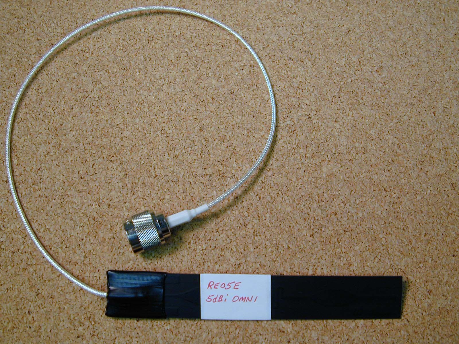
MYF-XI-325
May 25, 2004Spread Spectrum Transmission System
Equipment Class
DTS - Digital Transmission System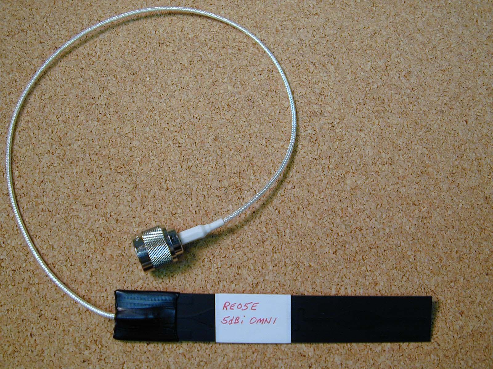
MYF-G11FNFPC
Mar 09, 2004Extended Range Wireless LAN
Equipment Class
DTS - Digital Transmission System