MYF-HYPER24CLAWireless Bridge Transmitter
L-Com, Inc.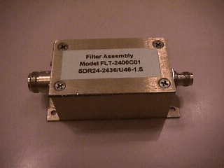
Click to zoom
Application Details
- Equipment Class
- DSS - Part 15 Spread Spectrum Transmitter
- Date of Grant
- Aug 11, 1998
- Application Purpose
- Original Equipment
- Date of Application
- Jun 15, 1998
- Equipment Note
- Wireless Bridge Transmitter
- Frequency Range
- 2436.00000000 - 2436.00000000
- Company
- L-Com, Inc.
- Country
- United States
Documents & Files
Document Text
Text extracted from the exhibit documents filed with the FCC. Open a document above to read the original.
Users Manual
Clarion/Hyperlink Bridge Kit Installation Manual Rev. A Page 1 Hyperlink Technologies, Inc. Hyperlink/Clarion Extended Range Wireless LAN Bridge Kit Featuring the Clarion JX-4000 10 Mbit/sec Wireless Bridge Installation Manual Clarion/Hyperlink Bridge Kit Installation Manual Rev. A Page 2 Hyperlink Technologies, Inc. Copyright © 1996, Clarion Corporation of America. All rights reserved. No part of the contents of this document may be transmitted or reproduced in any form or by any means without the written permission of Clarion Corporation of America. Portions Copyright © 1998, Hyperlink Technologies, Inc. All rights reserved HyperGain and HyperAmp are trademarks of Hyperlink Technologies, Inc. WARNINGS The manufacturer assumes no responsibility for damage caused by interference due to this equipment. Clarion/Hyperlink Bridge Kit Installation Manual Rev. A Page 3 Hyperlink Technologies, Inc. Contents FCC Radio Interference Statement 4 Introduction 5 Features of the JX4000 5 Types of Installations 6 System Requirements 7 Kit Contents 7 Tools Required 7 JX-4000 Front & Rear Panel Features 8 Connections & Features of the Amplified Antenna 9 The DC Power Injector/Lightning Protector10 Overall System Configuration11 Antenna System Connections12 Surveying the Antenna Site12 Preparing for System Installation13 Mounting & Cabling the Amplified Antenna System13 Basic System Checks15 Amplifier & DC Power Injector LEDs15 JX-4000 LED Diagnostic Displays16 Clarion JX-4000 Specifications17 APPENDICES Antenna Mounting Instructions Appendix A Clarion/Hyperlink Bridge Kit Installation Manual Rev. A Page 4 Hyperlink Technologies, Inc. Radio Frequency Interference Statement USA - Federal Communications Commission (FCC): This device complies with Part 15 of FCC Rules. Operation of this device is subject to the following two conditions: This device may not cause harmful interference. This device must accept any interference that may cause undesired operation. Information to User: This device must be installed and used in strict accordance with the manufacturer's instructions. However, there is no guarantee that interference to radio communications will not occur in a particular commercial installation. If this device does cause interference, which can be determined by turning the host equipment off and on, the user is encouraged to consult the instruction manual of the host equipment or the local device supplier. In case the device does cause harmful interference with an authorized radio service, the user/operator shall promptly stop operating the device until harmful interference has been eliminated. The manufacturer is not responsible for any radio or television interference caused by unauthorized modification of this device or the substitution or attachment of connecting cables and equipment other than those supplied. The correction of interference caused by such unauthorized modification, substitution or attachment will be the responsibility of the user. Clarion/Hyperlink Bridge Kit Installation Manual Rev. A Page 5 Hyperlink Technologies, Inc. Introduction The Clarion JX-4000 is a wireless transceiver providing 10 Mbit/sec burst data rate to support wireless connections in IEEE 802.3 and Ethernet II (TCP/IP) LAN. Equipped with a Hyperlink Extended Range Amplified Antenna System, the JX-4000 offers an ultra high-performance long-range building-to-building network bridge. The JX-4000 functions as an Ethernet MAU. It uses a state-of-the-art spread spectrum technology to implement robust 10 Mbps burst transmission. It also actualizes efficient utilization of frame buffers and coordination of RF and wired interface traffic to maintain high throughput. The JX-4000 offers true “Plug and Play” installation. No additional driver software is required for operation. That is, the JX-4000 can be connected not only to a computer but also to a hub or to a router. FEATURES OF THE JX-4000 The Clarion JX-4000 has the following features: • Full wireless Ethernet 10 Mbps data rate. • State-of-the-art spread spectrum technology provides reliable, secure, long range, radio link operation. • True “Plug and Play” installation for compatibility with all 802.3 and Ethernet II LAN devices, all operating systems and all protocol stacks. Clarion/Hyperlink Bridge Kit Installation Manual Rev. A Page 6 Hyperlink Technologies, Inc. Types of Installations The type of application will determine which type of kit to install: Building-to-Building or Tower-to-Tower: Typically these installations will typically require directional Yagi or Grid Antenna kits. Central Node in a Multipoint Network or Mobile Network: This type of installation typically requires an Omni Directional Kit at the central node for 360 degree coverage. System Requirements The Clarion/HyperGain™ Amplified Extended Range Bridge Kit provides a Clarion/Hyperlink Bridge Kit Installation Manual Rev. A Page 7 Hyperlink Technologies, Inc. complete plug-and-play solution for linking buildings in an outdoor environment. All you need to add is suitable masts or towers and some basic site planning. Please read this manual in its entirety before beginning the installation. Kit Contents: Each Kit contains the following items: Clarion JX-4000 Radio and DC Power Supply HyperAmp Remote Mounted Amplifier HyperGain Antenna (Omni, Yagi, or Grid) HyperGain DC Power Injector/Lightning Protector Signal Filter 50 ft. Antenna Cable 4 ft. Jumper Cable Mounting Hardware Sealant Tape Manual Tools Required: 7/16" open-end wrench or Adjustable Wrench #12-10 AWG or similar wire (for grounding) Wire Cutter / Stripper Pliers Other Required Equipment: Suitable mast or tower hardware AUI Transceiver Cable AUI-equipped Network Hub or Card Other Helpful Equipment and Tools: Cellular telephones or Walkie-talkies Binoculars Compass Handheld GPS Clarion/Hyperlink Bridge Kit Installation Manual Rev. A Page 8 Hyperlink Technologies, Inc. JX-4000 Front and Rear Panel Features Internal antenna (inside of the top …
Text truncated - open the document above for the full version.
Contact Information
Applicant
Kenneth Burgner(Product Manager)
Technical Contact
Hyperlink Technologies, Inc.Peter J Roth
[email protected]561-995-2256
1200 Clint Moore Road · Boca Raton, Florida · United States
Test Firm
University of MichiganValdis Liepa
Technical Specifications
| # | Rule Parts | Frequency Range | Power Output |
|---|---|---|---|
| 1 | - | 2.44 GHz - 2.44 GHz | 160.00 mW |
Other Applications from L-Com, Inc.
MYF-LCUSB2415
Aug 17, 20142.4 GHz 802.11n Wireless USB Adapter
Equipment Class
DTS - Digital Transmission System
MYF-LCUSB
Apr 26, 2010802.11b/g USB Dongle with Amplifier
Equipment Class
DTS - Digital Transmission System
MYF-LCUSBX
Apr 15, 2010802.11b/g USB Dongle with Amplifier
Equipment Class
DTS - Digital Transmission System
MYF-XI-325
May 25, 2004Spread Spectrum Transmission System
Equipment Class
DTS - Digital Transmission System
MYF-XI-325X
May 16, 2004Spread Spectrum Transmission System
Equipment Class
DTS - Digital Transmission System