MYF-WL-2401Spread Spectrum Transmission System
L-Com, Inc.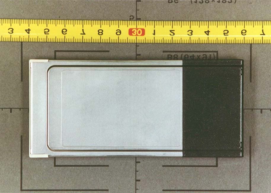
Click to zoom
Application Details
- Equipment Class
- DSS - Part 15 Spread Spectrum Transmitter
- Date of Grant
- Oct 05, 2002
- Application Purpose
- Original Equipment
- Date of Application
- Oct 05, 2002
- Equipment Note
- Spread Spectrum Transmission System
- Frequency Range
- 2412.00000000 - 2462.00000000
- Company
- L-Com, Inc.
- Country
- United States
Documents & Files
Document Text
Text extracted from the exhibit documents filed with the FCC. Open a document above to read the original.
Users Manual
USER’S MANUAL INFORMATION (PRELIMINARY) The User’s Manual is in preparation. The following material will be contained in the manual: FCC ID: MYF-WL-2401 IC: 2837A -WL-2401 This device complies with Part 15 of the FCC Rules and with RSS- 210 of I ndustry Canada. Operation is subject to the following two conditions: (1) This device may not cause harmful interference, and (2) This device must accept any interference received, including interference that may cause undesired operation. WARNING: Changes or modifications not expressively approved by the party responsible for compliance could void the user's authority to operate the equipment. The term “IC:” before the radio certification number only signifies that Industry Canada technical specifications were met. NOTE: The antenna system shall be installed ONLY by experienced antenna installers who are familiar with local building and safety codes, and wherever necessary have been licensed by appropriate government regulatory bodies. Failure to do so may void the Product Warranty, as well as expose the end-user to legal and/or financial liabilities. Hyperlink Technologies, its agents, resellers or distributors, are not liable for injury, damage, or violation of government regulations that may arise from failing to comply with the guidelines described in this document. Caution: Exposure to Radio Frequency Radiation. The radiated output power of this product is below the FCC radio exposure limits. Nevertheless, this product shall be used in such a manner that the potential for human contact during normal operation is minimized. Antenna shall be mounted in such a manner as to minimize the potential for human contact during normal operation. In order to avoid the possibility of exceeding the FCC radio frequency exposure limits, human proximity to the antenna shall not be less than 20 cm (8 inches) during normal operation. Hyperlink Technologies is not responsible for any radio or television interference caused by unauthorized modification of this device or the substitution or attachment of connecting cables and equipment other than specified by Hyperlink Technologies. The correction of interference caused by such unauthorized modification, substitution or attachment will be the responsibility of the user. The following table summarizes the minimum separation distance as calculated following FCC OET Bulletin 65. Because of the large variation in antenna and amplifier configurations, minimum separation distance is calculated over the full range of total EIRP only. To obtain the minimum separation distance for a particular system, the antenna gain (dBm) listed in Table 1.2 must be added to the amplifier output power (dBm) listed in Table 1.3, resulting in the total EIRP for a given system. If no amplifier is used, the output power of the radio from Table 1.2 is to be used in place of the amplifier output power. Cross referencing this EIRP (dBm) with that listed below will give the corresponding minimum separation distance for the given system. NOTE: THE ONLY PERMISSIBLE SYSTEM CONFIGURATIONS ARE THOSE LISTED IN THE SYSTEM CONFIGURATION TABLE AT THE END OF THIS MANUAL. Table 1.1 Potential Health Hazard Radiation Level EIRP(dBm) R (cm) EIRP(dBm) R (cm) EIRP(dBm) R (cm) 54 141.4 36 17.8 18 2.2 53 126.0 35 15.9 17 2.0 52 112.3 34 14.1 16 1.8 51 100.1 33 12.6 15 1.6 50 89.2 32 11.2 14 1.4 49 79.5 31 10.0 13 1.3 48 70.9 30 8.9 12 1.1 47 63.2 29 8.0 11 1.0 46 56.3 28 7.1 10 0.9 45 50.2 27 6.3 9 0.8 44 44.7 26 5.6 8 0.7 43 39.8 25 5.0 7 0.6 42 35.5 24 4.5 6 0.6 41 31.7 23 4.0 5 0.5 40 28.2 22 3.6 4 0.4 39 25.1 21 3.2 3 0.4 38 22.4 20 2.8 2 0.4 37 20.0 19 2.5 1 0.3 Table 1.2 Amplifier Output Power Ratings Amplifier Model Output Power (dBm) None (Radio only) 11.0 HA2401-AGC -250 24.0 HA2401-AGC500 27.0 HA2401-AGC1000 30.0 Table 1.3 Antenna Gain Antenna Model Construction Gain (dBi) HG2401U whip/monopole 1 HG2405U whip/monopole 5 HG2406U whip/monopole 6 HG2407U whip/monopole 7 HG2408U whip/monopole 8 HG2409U whip/monopole 9 HG2410U whip/monopole 10 HG2412U whip/monopole 12 HG2415U whip/monopole 15 HG2403MU whip/automotive 3 HG2405MU whip/automotive 5 HG2408P patch 8 HG2409P patch 9 HG2413P patch 13 HG2414P patch 14 HG2416P patch 16 HG-UNI-16 patch 16 HG2412P linear array 12 HG2415P linear array 15 HG2417P linear array 17 HG2420P linear array 20 HG2412Y Yagi-Uda 12 HG2415Y Yagi-Uda 15 HG2414D dish 15 HG2415G dish 19 HG2419G dish 21 HG2421G dish 24 WARNING: It is the responsibility of the professional installer to ensure that when using the outdoor antenna kits in the United States (or where the FCC rules apply), only these antenna configurations shown in the table above and which are described in this document are used. The use of any other than those listed is expressly forbidden in accordance to FCC rules CFR47 part 15.204. HYPERLINK LUCENT/ORINOCOFCC ID: MYF-WL-2401IC: 2837A-WL2401 HA2401-AGC1000 HA2401-AGC500 HA2401-AGC-250 HA2401-AGC1000 HA2401-AGC500 HA2401-AGC-250 HA2401-AGC1000 HA2401-AGC500 HA2401-AGC-250 HA2401-AGC1000 HA2401-AGC500 HA2401-AGC-250 HA2401-AGC1000 HA2401-AGC500 HA2401-AGC-250 HA2401-AGC1000 HA2401-AGC500 HA2401-AGC-250 HA2401-AGC1000 HA2401-AGC500 HA2401-AGC-250 HA2401-AGC1000 HA2401-AGC500 HA2401-AGC-250 HA2401-AGC1000 HA2401-AGC500 HA2401-AGC-250 HA2401-AGC1000 HA2401-AGC500 HA2401-AGC-250 HA2401-AGC1000 HA2401-AGC500 HA2401-AGC-250 302724302724302724302724302724302724302724302724302724302724302724 ANTENNAGAIN (dBi) HG2401U1 XXXXXXXXXXXXXXXXXXXXXX HG2405U5 XXXXXXXXXXXXXXXXXXXXXXXXXXXX HG2406U6 XXXXXXXXXXXXXXXXXXXXXX HG2407U7 XXXXXXXXXXXXXXXXXXXXXX HG2408U8 XXXXXXXXXXXXXXXXXXXXXX HG2409U9 XXXXXXXXXXXXXXXXXXXXXX HG2410U10 XXXXXXXXXXXXXXXXXXXXXX HG2412U12 XXXXXXXXXXXXXXXXXXXXXX HG2415U15 XXXXXXXXXXXXXXXXXXXXXX HG2403MU3 XXXXXXXXXXXXXXXXXXXXX HG2405MU5 XXXXXXXXXXXXXXXXXXXXX HG2408P8 XXXXXXXXXXXXXXXXXXXX HG2409P9 XXXXXXXXXXX HG2413P13 XXXXXXXXXXX HG2414P14 XXXXXXXXXXX HG2416P16 XXXXXXXXXXX HG-UNI-1616 XXXXXXXXXXX HG2412P12 XXXXXXXXXXXXXXXXX…
Text truncated - open the document above for the full version.
Block Diagram
SYSTEM BLOCK DIAGRAM FCC ID: MYF-WL-2401 HYPERLINK TECHNOLOGIES, INC. The overall system configuration is shown below: DC INJECTOR BLOCK DIAGRAM FCC ID: MYF-WL-2401 HYPERLINK TECHNOLOGIES, INC. DC Injector Model BT2404 FROM PC CARDTO ANTENNA RFRF and DC POWER DC FROM POWER SUPPLY TRANSMIT POWER SENSING INPUT ATTENUATOR (FACTORY CONFIGURABLE T/R SWITCH CONTROL RECEIVE LNABANDPASS FILTER TRANSMIT POWER AMPLIFIER T/R SWITCH T/R SWITCH TO / FROM RADIO TO / FROM ANTENNA AMPLIFIER BLOCK DIAGRAM FCC ID: MYF-WL-2401 HYPERLINK TECHNOLOGIES, INC. Amplifier Model HA2401
Cover Letter(s)
Re: Certification for Hyperlink Wireless LAN Model: MYF-WL-2401 FCC ID: MYF-WL-2401 IC: 2837A-WL-2401 REQUEST FOR CONFIDENTIALITY Pursuant to 47 CRF 0.459, Hyperlink requests that a part of the subject application be held confidential. This comprises Exhibits (5) Schematics (10) Parts List (Part of Exhibit only) Hyperlink has spent substantial effort in developing this product and it is one of the first of its kind in industry. Having the subject information easily available to "competition" would negate the advantage they have achieved by developing this product. Not protecting the details of the design will result in financial hardship. If there are any questions regarding this request, please contact me at the above address or call 734-483-4211, fax 734-647-2106 or e-mail [email protected]. Sincerely, Valdis V. Liepa Research Scientist University of Michigan October 2, 2002 Re: Certification for Hyperlink Wireless LAN Model: MYF-WL-2401 FCC ID: MYF-WL-2401 IC: 2837A-WL-2401 STATEMENT OF MODIFICATIONS There were no modifications made to the DUT by this test laboratory. However, the number of channels used in any particular configuration was adjusted if necessary so as to meet the FCC and IC limits in restricted bands. (Also see Section 3.1 of the attached Test Report). _____________________ Valdis V. Liepa Research Scientist Re: Certification for Hyperlink Wireless LAN Model: MYF-WL-2401 FCC ID: MYF-WL-2401 IC: 2837A-WL-2401 GENERAL PRODUCT INFORMATION The device, for which certification is pursued, has been designed by: Hyperlink Technologies Inc 2837A-WL-2401 1200 Clint Moore Road, Suite 14 Boca Raton, Florida 33487 Peter Roth Tel: (561) 995-2256 Fax: (561) 995-2432 It will be manufactured by: Hyperlink Technologies Inc 1200 Clint Moore Road, Suite 14 Boca Raton, Florida 33487 Peter Roth Tel: (561) 995-2256 Fax: (561) 995-2432 Canadian Contact: Guy Simard P.O. Box 68036 1083 Boulevard Cure Labelle Blainville, QU J7C 4Z4 Re: Certification for Hyperlink Wireless LAN Model: MYF-WL-2401 FCC ID: MYF-WL-2401 IC: 2837A-WL-2401 POWER OF ATTORNEY A letter granting Valdis V. Liepa the Power of Attorney is on file and can be provided when so requested.
Cover Letter(s)
HYPERLINK LUCENT/ORINOCOFCC ID: MYF-WL-2401IC: 2837A-WL2401 HA2401-AGC1000 HA2401-AGC500 HA2401-AGC-250 HA2401-AGC1000 HA2401-AGC500 HA2401-AGC-250 HA2401-AGC1000 HA2401-AGC500 HA2401-AGC-250 HA2401-AGC1000 HA2401-AGC500 HA2401-AGC-250 HA2401-AGC1000 HA2401-AGC500 HA2401-AGC-250 HA2401-AGC1000 HA2401-AGC500 HA2401-AGC-250 HA2401-AGC1000 HA2401-AGC500 HA2401-AGC-250 HA2401-AGC1000 HA2401-AGC500 HA2401-AGC-250 HA2401-AGC1000 HA2401-AGC500 HA2401-AGC-250 HA2401-AGC1000 HA2401-AGC500 HA2401-AGC-250 HA2401-AGC1000 HA2401-AGC500 HA2401-AGC-250 302724302724302724302724302724302724302724302724302724302724302724 ANTENNAGAIN (dBi) HG2401U1 XXXXXXXXXXXXXXXXXXXXXX HG2405U5 XXXXXXXXXXXXXXXXXXXXXXXXXXXX HG2406U6 XXXXXXXXXXXXXXXXXXXXXX HG2407U7 XXXXXXXXXXXXXXXXXXXXXX HG2408U8 XXXXXXXXXXXXXXXXXXXXXX HG2409U9 XXXXXXXXXXXXXXXXXXXXXX HG2410U10 XXXXXXXXXXXXXXXXXXXXXX HG2412U12 XXXXXXXXXXXXXXXXXXXXXX HG2415U15 XXXXXXXXXXXXXXXXXXXXXX HG2403MU3 XXXXXXXXXXXXXXXXXXXXX HG2405MU5 XXXXXXXXXXXXXXXXXXXXX HG2408P8 XXXXXXXXXXXXXXXXXXXX HG2409P9 XXXXXXXXXXX HG2413P13 XXXXXXXXXXX HG2414P14 XXXXXXXXXXX HG2416P16 XXXXXXXXXXX HG-UNI-1616 XXXXXXXXXXX HG2412P12 XXXXXXXXXXXXXXXXXXXX HG2415P15 XXXXXXXXXXX HG2417P17 XXXXXXXXXXX HG2420P20 XXXXXXXXXXXXXXX HG2412Y12 XXXXXXXXXXXXXXXXXX HG2415Y15 XXXXXXXXXXXXXXXXXXXXX HG2414D14 XXXXXXXXXXXXXX HG2415G15 XXXXXXXXXXXXXXXXX HG2419G19 XXXXXXXXXXX HG2421G21 XXXXXXXXXXX HG2424G24 XXXXXXXXXXXX XConfigurations tested to demonstrate FCC/IC compliance XConfigurations that comply with FCC/IC regulations XConfigurations that reqiure a filter between the radio and the DC injector (tested) NoneNoneNoneNoneNone 24472452 AMPLIFIER MODEL: NoneNoneNone 24322437 None 244224572462 OUTPUT POWER (dBm): 2412241724222427CHANNEL FREQUENCY (MHz): NoneNone
Cover Letter(s)
October 2, 2002 American Telecommunications Certification Body, Inc. 6731 Whittier Avenue Suite C110 McLean, VA 22101 RE: Certification Application FCC ID: MYF-WL-2401 Please find enclosed application materials for certification of Hyperlink MYFWL2401 Wireless LAN. This system consists of 3 AGC amplifiers and 28 antennas. The highest and lowest antennas in each “class” were tested with the highest and lowest amplifiers in the system. The resulting configurations, including permissible channels and antenna amplifier combinations, are included under the System Configuration Info. Exhibit. Demonstrations of amplifier linearity with respect to AGC amplifier input power levels are provided as an annex to the Test Report. Additional information about the construction of the amplifiers and relevance to the set of tests performed is provided in the Schematics exhibit. We feel that the set of tests performed covers the worst case emissions for all of the configurations that we request certification for, as per conversations with Bill Graff and Tim Johnson there at ATCB. Note: The test report annex is used in more than one FCC filing, and includes some additional amplifiers that are not requested to be part of this certification. If there are any questions regarding the application or testing performed, please contact me at the above address or call 734-483-4211, fax 734-647-2106, or e-mail [email protected]. Sincerely, Valdis V. Liepa Research Scientist
External Photos
Location of FCC ID Label Image Copyright 2002, Hyperlink Technologies, Inc. All rights reserved. HyperLink Power Injector (Top) HyperLink Power Injector (Bottom) HyperLink Antenna, Model HG2403MU HyperLink Antenna, Model HG2405MU HG2403MU (with and without radome installed) HG2405MU (left) and HG2405U (right) HG2406UHG2407U HG2408UHG2409U HG2410UHG2412U HG2401UHG-UNI-16 HG2408PHG2409P HG2412PHG2413P HG2414PHG2415P HG2417PHG2420P HG2412YHG2415Y HG2416P HG2415U HG2415GHG2419G HG2421GHG2424G HG2414D
ID Label/Location Info
Location of FCC ID Label Image Copyright 2002, Hyperlink Technologies, Inc. All rights reserved.
Internal Photos
Amplifier Internal PCB Top Image Copyright 2002, Hyperlink Technologies, Inc. All rights reserved. Amplifier Internal PCB Bottom Image Copyright 2002, Hyperlink Technologies, Inc. All rights reserved.
Operational Description
Hyperlink Extended Range Wireless LAN Product Description The Hyperlink Extended Range Wireless LAN Kit is a direct sequence spread spectrum wireless transceiver providing 11 Mbit/sec data rate to support wireless connections in an IEEE 802.3 LAN. Equipped with a Hyperlink Extended Range Amplified Antenna System, this product offers a high-performance long-range building-to-building wireless networking solution. This kit incorporates state-of-the-art direct sequence spread spectrum technology to implement robust 11 Mbps transmission, and offers true “Plug and Play” installation. This system has the following features: • IEEE 802.11b Compatibility. • Wireless 11 Mbps data rate. • State-of-the-art spread spectrum technology provides reliable, secure, long range, radio link operation. • True “Plug and Play” installation for compatibility with all 802.3 and Ethernet II LAN devices, all operating systems and all protocol stacks. • PCMCIA Form Factor • Bi-directional amplifier with Automatic Gain Control to optimize transmit power and eliminate the effects of system cable losses.
RF Exposure Info
RF EXPOSURE The following table summarizes the minimum separation distance as calculated following FCC OET Bulletin 65. Because of the large variation in antenna and amplifier configurations, minimum separation distance is calculated over the full range of total EIRP only. To obtain the minimum separation distance for a particular system, the antenna gain (dBm) listed in Table 1.2 must be added to the amplifier output power (dBm) listed in Table 1.3, resulting in the total EIRP for a given system. If no amplifier is used, the output power of the radio from Table 1.2 is to be used in place of the amplifier output power. Cross referencing this EIRP (dBm) with that listed below will give the corresponding minimum separation distance for the given system. NOTE: THE ONLY PERMISSIBLE SYSTEM CONFIGURATIONS ARE THOSE LISTED IN THE SYSTEM CONFIGURATION INFORMATION EXHIBIT. Table 1.1 Potential Health Hazard Radiation Level EIRP(dBm) R (cm) EIRP(dBm) R (cm) EIRP(dBm) R (cm) 54 141.4 36 17.8 18 2.2 53 126.0 35 15.9 17 2.0 52 112.3 34 14.1 16 1.8 51 100.1 33 12.6 15 1.6 50 89.2 32 11.2 14 1.4 49 79.5 31 10.0 13 1.3 48 70.9 30 8.9 12 1.1 47 63.2 29 8.0 11 1.0 46 56.3 28 7.1 10 0.9 45 50.2 27 6.3 9 0.8 44 44.7 26 5.6 8 0.7 43 39.8 25 5.0 7 0.6 42 35.5 24 4.5 6 0.6 41 31.7 23 4.0 5 0.5 40 28.2 22 3.6 4 0.4 39 25.1 21 3.2 3 0.4 38 22.4 20 2.8 2 0.4 37 20.0 19 2.5 1 0.3 The following equations were used in calculating the operating distance (R). 10 )( 10)()( dBGain mWPomWEIRP⋅= and )/(4 )( 2 cmmWS mWEIRP R ⋅Π⋅ =, S = 1mW/cm 2 Table 1.2 Amplifier Output Power Ratings Amplifier Model Output Power (dBm) None (Radio only) 11.0 HA2401-AGC10 10.0 HA2401-AGC16 12.0 HA2401-AGC50 17.0 HA2401-AGC100 20.0 HA2401-AGC250 24.0 HA2401-AGC-250 24.0 HA2401-AGC500 27.0 HA2401-AGC1000 30.0 Table 1.3 Antenna Gain Antenna Model Construction Gain (dBi) HG2401U whip/monopole 1 HG2405U whip/monopole 5 HG2406U whip/monopole 6 HG2407U whip/monopole 7 HG2408U whip/monopole 8 HG2409U whip/monopole 9 HG2410U whip/monopole 10 HG2412U whip/monopole 12 HG2415U whip/monopole 15 HG2403MU whip/automotive 3 HG2405MU whip/automotive 5 HG2408P patch 8 HG2409P patch 9 HG2413P patch 13 HG2414P patch 14 HG2416P patch 16 HG-UNI-16 patch 16 HG2412P linear array 12 HG2415P linear array 15 HG2417P linear array 17 HG2420P linear array 20 HG2412Y Yagi-Uda 12 HG2415Y Yagi-Uda 15 HG2414D dish 15 HG2415G dish 19 HG2419G dish 21 HG2421G dish 24
Test Report
1 The University of Michigan Radiation Laboratory 3228 EECS Building Ann Arbor, MI 48109-2122 Tel: (734) 764-0500 Measured Radio Frequency Emissions From HyperlinkTechnologies Inc Model: MYF-WL-2401 Report No. 139 October 4,2002 Copyright © 2002 For: Hyperlink Technologies Inc 1200 Clint Moore Road, Suite 14 Boca Raton, Florida 33487 Contact: Peter Roth Tel:(561) 995-2256 Fax: (561) 995-2432 PO: Verbal Tests supervised by: Measurements made by:Report approved by: ____________________ Joseph D BrunettValdis V. Liepa Research Scientist ___________________________________________________________________________ Summary Tests for compliance with FCC Regulations, Part 15.247, and with Industry Canada Regulations, RSS-210, Section 6.2.2 (o), were performed on HyperLink spread spectrum RF Extended Range LAN System. The DUT is subject to the Rules and Regulations as a transmitter and a digital device. This link uses an FCC certified spread spectrum Lucent radio, but adds cables, amplifiers, and external antennas. Here we report on the results of measurements for combinations of antennas and amplifiers. In testing completed 25-Sep-02, the worst radiated emissions in restricted bands were met by 0.9 dB at a frequency of 2390 MHz (see pp. 11-K). 2 1. Introduction HyperLink/Lucent Extended Range Radio, Model MYF-WL-2401, was tested for compliance with FCC Regulations, Part 15, adopted under Docket 87-389, April 18, 1989, and with Industry Canada RSS-210, Issue 5, Draft 1, Section 6.2.2 (t1). The tests were performed at the University of Michigan Radiation Laboratory Willow Run Test Range following the procedures described in ANSI C63.4-1992 "Methods of Measurement of Radio-Noise Emissions from Low-Voltage Electrical and Electronic Equipment in the Range of 9 kHz to 40 GHz". The Site description and attenuation characteristics of the Open Site facility are on file with FCC Laboratory, Columbia, Maryland (FCC Reg. No: 91050) and with Industry Canada, Ottawa, ON (File Ref. No: IC 2057). 2. Test Procedure and Equipment Used The test equipment commonly used in our facility is listed in Table 2.1 below. The HP 8593A spectrum analyzer is used for primary amplitude and frequency reference. Table 2.1 Test Equipment Test InstrumentEqpt. UsedManufacturer/Model Spectrum Analyzer (0.1-1500 MHz) Hewlett-Packard, 182T/8558B Spectrum Analyzer (9kHz-22GHz)XHewlett-Packard 8593A SN: 3107A01358 Spectrum Analyzer (9kHz-26GHz)XHewlett-Packard 8593E, SN: 3412A01131 Spectrum Analyzer (9kHz-26GHz)Hewlett-Packard 8563E, SN: 3310A01174 Spectrum Analyzer (9kHz-40GHz)Hewlett-Packard 8564E,SN: 3745A01031 Power MeterXHewlett-Packard, 432A PowerMeterAnritsu, ML4803A/MP Peak Power MeterXPacific Instruments 1018B Harmonic Mixer (26-40 GHz)Hewlett-Packard 11970A, SN: 3003A08327 Harmonic Mixer (40-60 GHz)Hewlett-Packard 11970U, SN: 2332A00500 Harmonic Mixer (75-110 GHz)Hewlett-Packard 11970W,SN: 2521A00179 Harmonic Mixer (140-220 GHz)Pacific Millimeter Prod., GMA, SN: 26 S-Band Std. Gain Horn XS/A, Model SGH -2.6 C-Band Std. Gain Horn XUniversity of Michigan, NRL design XN-Band Std. Gain Horn XUniversity of Michigan, NRL design X-Band Std. Gain Horn XS/A, Model 12-8.2 X-band horn (8.2- 12.4 GHz)XNarda 640 X-band horn (8.2- 12.4 GHz)Scientific Atlanta , 12-8.2, SN: 730 K-band horn (18-26.5 GHz)XFXR, Inc., K638KF Ka-band horn (26.5-40 GHz)XFXR, Inc., U638A U-band horn (40-60 GHz)Custom Microwave, HO19 W-band horn(75-110 GHz)Custom Microwave, HO10 G-band horn (140-220 GHz)Custom Microwave, HO5R Bicone Antenna (30-250 MHz)XUniversity of Michigan, RLBC-1 Bicone Antenna (200-1000 MHz)XUniversity of Michigan, RLBC-2 Dipole Antenna Set (30-1000 MHz) XUniversity of Michigan, RLDP-1,-2,-3 Dipole Antenna Set (30-1000 MHz) EMCO 2131C, SN: 992 Active Rod Antenna (30 Hz-50 MHz)EMCO 3301B, SN: 3223 Active Loop Antenna (30 Hz-50 MHz)EMCO 6502, SN:2855 Ridge-horn Antenna (300-5000 MHz)XUniversity of Michigan Amplifier (5-1000 MHz)XAvantak, A11-1, A25-1S Amplifier (5-4500 MHz)XAvantak Amplifier (4.5-13 GHz)XAvantek, AFT-12665 Amplifier (6-16 GHz)XTrek Amplifier (16-26 GHz)XAvantek LISN BoxUniversity of Michigan Signal GeneratorHewlett-Packard 8657B 3 3. Configuration and Identification of Device Under Test The DUT is a spread spectrum RF wireless link operating in 2400 - 2483.5 MHz band. The system tested consisted of a laptop computer,Lucent radio, coax cable, (choice of) amplifier, (choice of) band-pass filter, and (choice of) an antenna. The system has been designed to operate with up to 12channels from 2412 to 2462 MHz.; however, depending on the choice of components used (amplifier, filter, antenna), channels are restricted so as to meet the FCC and IC emissions limits. The DUT was designed and manufactured by Hyperlink Technologies Inc, 1200 Clint Moore Road, Suite 14, Boca Raton, Florida 33487. Figure 3.1 shows the block diagram of the basic system. It is identified as: HyperlinkTechnologies Inc. Model: MYF-WL-2401 FCC ID: MYF-WL-2401 IC: 2837A-WL-2401 14 configurations were tested for radiated emissions compliance. It is the intent of this test report to demonstrate compliance for the full set of configurations listed in the System Conf.Information exhibit included in this filing. Laptop computer with PCMCIA Radio DC injector (if needed) Amplfier (if needed) Antenna Antenna Cable Pigtail RF Filter (if needed) Figure 3.1Basic block diagram of the system With components evaluated: Wireless Radio Lucent RadioSN:01UT33373491 ModelOrinoco GoldFCC ID:IMRWLPCEL4H CAN:230391152A Laptop Computer IBM Thinkpad 710CSN: 23-RYY74 FCC ID: ANO263OCS Amplifier(s) Table 3.1 Amplifiers Amplifier ModelOutput Power (dBm) Used in Testing HA2401-AGC-25024.0X HA2401-AGC50027.0 HA2401-AGC100030.0X 4 Power Supply , for amplifier(s) Sunfone Model: ACSM-26 (certified underFCC ID: MYFWL2401) FCCClass A Model: ACSD-05 (certified underFCC ID: MYFWL2401) FCCClass B DC Injector HyperLinkSN: none Filters Bandpass Filter, 4-pole, Model: FLT-2437-20-4(BLK) Cables Antenna cable, …
Text truncated - open the document above for the full version.
Test Report
1 Annex-A: Emissions Variations Over a Wide Range of Input Power Levels 1. Purpose The purpose of this annex is to demonstrate that Hyperlink Technologies’ HA2401-AGCXXXX AGC amplifiers have no emissions variations over a wide range of input power levels. 2. Amplifier Construction The HA2401-AGCXXXX amplifiers can be broken down into two categories, each with a different construction and schematic. The low power type, HA2401-AGC010 to HA2401- AGC250, and the higher power HA2401-AGC-250 to HA2401-AGC1000. (The extra dash in the HA2401-AGC-250 is used to discriminate it from the equivalent powered HA2401-AGC250 at this time.) Depending on the filing, one or the other type of amplifier is of concern; both are included herein. A detailed block diagram and schematic, Exh 05 – Schematics(Amplifiers).pdf, has been filed as a confidential part of this submission. Detailed information regarding the construction of these amplifiers and an explanation of their implementation relating to this matter is included in that portion of the filing. This information has been deemed CONFIDENTIAL by Hyperlink Technologies, and is therefore not included here. 3. Measurements For six configurations of the HA2401-AGCXXX amplifiers, the devices were tested for output power and conducted emissions with regards to the FCC and IC limits. The flowing graphs and tables include the results of these measurements. Plots of the conducted measurements follow. (All tests in this ANNEX were performed using the LUCENT Radio, FCC ID: IMRWLPCEL4H.) Because of the physical construction of the amplifiers, as described in Section 2 of this annex, amplifiers intermediate to those tested will also demonstrate the characteristics measured below. 2 1.1 Antenna Output Power vs. Cable Attenuation / Cable Length For this measurement, the configurations were set in a test mode for continuous data transmission. A peak (diode detector) power meter was connected where the antenna attaches to the system. Since the DUT transmits in continuous mode, there is no adjustment needed to the readings. As seen in the following figures, the HA2401-AGCXXX amplifiers’ output power ratings remain within 0.5 dB of there initial value for up to 10 dB cable attenuation between the LUCENT radio and the amplifier. A measurement of the WBC400 cable used in testing maintains a 3dB/50ft loss at 2.437 GHz, thus permitting 150 ft of WBC400 cable between the radio and the power amplifier before amplifier output power is compromised. Amplifier power is always maximum when no additional cable is used in the system. Peak Amplifier Output Power vs. Cable Attenation 6 9 12 15 18 21 24 0246810121416 Attenuation at Input (dB) Peak Output Power (dBm) HA2401-AGC250HA2401-AGC100HA2401-AGC010 Peak Amplifier Output Power vs. Cable Attenation 21 24 27 30 33 0246810121416 Attenuation at Input (dB) Peak Output Power (dBm) HA2401-AGC-250HA2401-AGC1000 3 2. Conducted Emissions Measurements Configurations Tested: The six configurations in Table 1 were determined to be a representative sample because of the physical construction of the amplifiers, as described in Section 2 of this annex. Again, amplifiers intermediate to those tested will also demonstrate the characteristics measured. Table 1. Configurations Tested Amplifier Model Power Rating Category/Type Attenuation from Radio to Amplifier Input (dBm) HA2401-AGC010 10 mW Low Power 0 HA2401-AGC250 250 mW Low Power 0 HA2401-AGC250 250 mW Low Power 10 HA2401-AGC-250 250 mW High Power 0 HA2401-AGC1000 1000 mW High Power 0 HA2401-AGC1000 1000 mW High Power 10 No amplifier 11.75 mW Radio alone 0 Note: Some 60 pages of plots were taken during testing, and the data below summarizes the results of this testing. 2.1 Bandwidth (15.247(a)(2)) For this test, each configuration was put in a test mode for continuous data transmission. The spectrum analyzer was connected where the antenna attaches to the system. The analyzer was set for RBW=VBW=100 kHz, SPAN=100 MHz. The 6-dB bandwidth was measured for lowest, middle, and highest channels available for use. The results for the configurations measured are summarized below. HA2401-AGC010 with 0 dB attn. Frequency 6 dB Bandwidth 2.412 GHz 10.0 MHz 2.437 GHz 9.6 MHz 2.462 GHz 10.1 MHz HA2401-AGC250 with 0 dB attn. Frequency 6 dB Bandwidth 2.422 GHz 10.3 MHz 2.437 GHz 11.3 MHz 2.452 GHz 10.4 MHz HA2401-AGC250 with 10 dB attn. Frequency 6 dB Bandwidth 2.412 GHz 9.5 MHz 2.437 GHz 10.0 MHz 2.462 GHz 9.9 MHz 4 HA2401-AGC-250 with 0 dB attn. Frequency 6 dB Bandwidth 2.412 GHz 10.1 MHz 2.437 GHz 10.3 MHz 2.462 GHz 10.4 MHz HA2401-AGC1000 with 0 dB attn. Frequency 6 dB Bandwidth 2.412 GHz 11.4 MHz 2.437 GHz 10.3 MHz 2.462 GHz 11.3 MHz HA2401-AGC1000 with 10 dB attn. Frequency 6 dB Bandwidth 2.412 GHz 10.1 MHz 2.437 GHz 10.1 MHz 2.462 GHz 9.5 MHz Radio Alone. Frequency 6 dB Bandwidth 2.412 GHz 10.2 MHz 2.437 GHz 10.1 MHz 2.462 GHz 10.1 MHz The introduction of attenuation between the radio and the AGC amplifier(s) does not affect the Channel Bandwidth in such a way as to cause a violation of FCC or IC guidelines. 2.2 RF Antenna Conducted Spurious Emissions (15.247(c)) For this test, each configuration was put in a test mode for continuous data transmission. The spectrum analyzer was connected where the antenna attaches to the system. The analyzer was set for RBW=100 kHz, VBW=300 kHz, the frequency was swept from 0 to 25 GHz. In the plots, only the fundamental is seen, the rest is noise. In all cases, the noise is at least 35 dB below the carrier. (Limit -20.0 dB below carrier). The introduction of attenuation between the radio and the AGC amplifier(s) does not affect the Conducted Spurious Emissions in such a way as to cause a violation of FCC or IC guidelines. 2.3 Power Spectral Density and Line Spacing (15.247(d)) For this test, each configuration was put in a test mode for continuous data transmission. The spectrum analyzer was connected where the antenna attaches to the system. The spectrum was first scanne…
Text truncated - open the document above for the full version.
Contact Information
Applicant
Kenneth Burgner(Product Manager)
Technical Contact
University of Michigan/EECSValdis V Liepa
[email protected]734 483 4211
1301 Beal Avenue · Ann Arbor, Michigan · United States
Test Firm
University of MichiganValdis Liepa
Technical Specifications
| # | Rule Parts | Frequency Range | Power Output |
|---|---|---|---|
| 1 | 15C | 2.41 GHz - 2.46 GHz | 933.00 mW |
Other Applications from L-Com, Inc.
MYF-LCUSB2415
Aug 17, 20142.4 GHz 802.11n Wireless USB Adapter
Equipment Class
DTS - Digital Transmission System
MYF-LCUSB
Apr 26, 2010802.11b/g USB Dongle with Amplifier
Equipment Class
DTS - Digital Transmission System
MYF-LCUSBX
Apr 15, 2010802.11b/g USB Dongle with Amplifier
Equipment Class
DTS - Digital Transmission System
MYF-XI-325
May 25, 2004Spread Spectrum Transmission System
Equipment Class
DTS - Digital Transmission System
MYF-XI-325X
May 16, 2004Spread Spectrum Transmission System
Equipment Class
DTS - Digital Transmission System