MYF-WL2401Hyperlink Extended Range Wireless LAN
L-Com, Inc.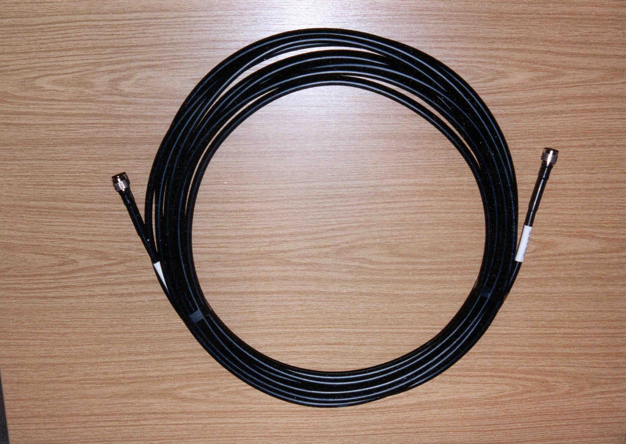
Click to zoom
Application Details
- Equipment Class
- DSS - Part 15 Spread Spectrum Transmitter
- Date of Grant
- Jul 17, 2000
- Application Purpose
- Original Equipment
- Date of Application
- May 14, 2000
- Equipment Note
- Hyperlink Extended Range Wireless LAN
- Frequency Range
- 2422.00000000 - 2452.00000000
- Company
- L-Com, Inc.
- Country
- United States
Documents & Files
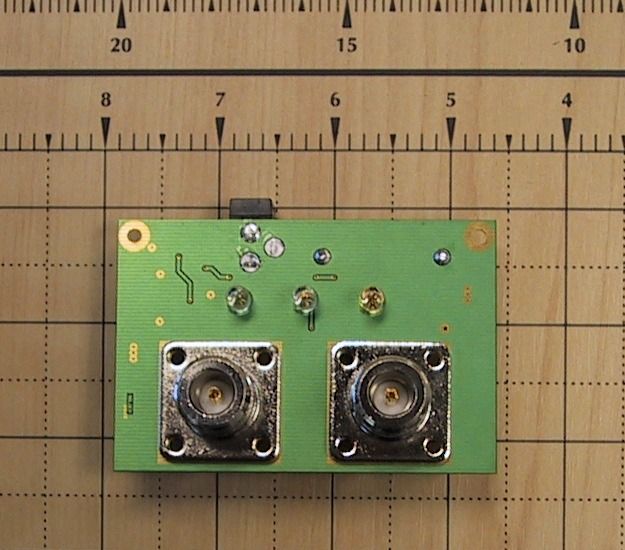
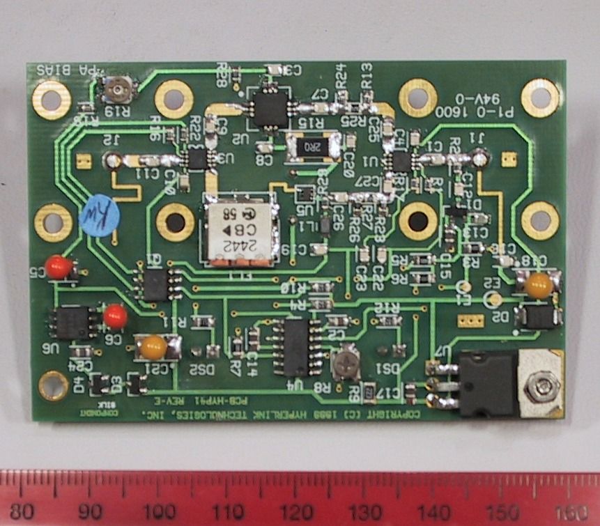
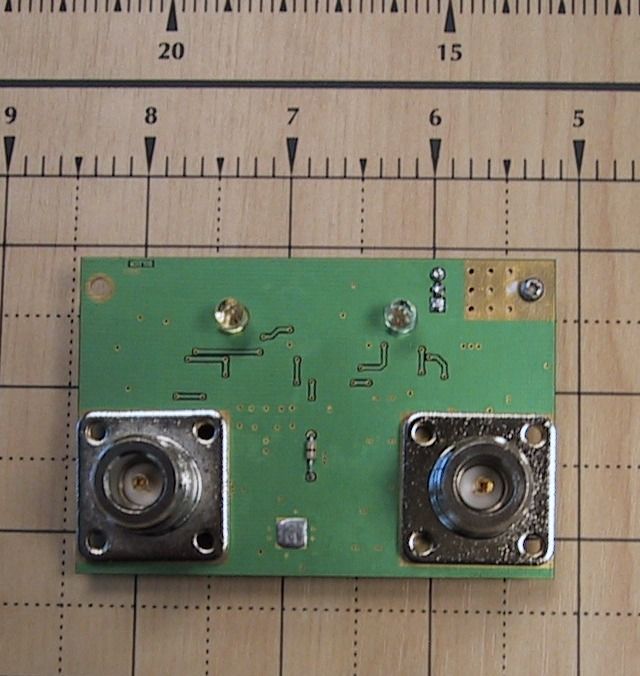
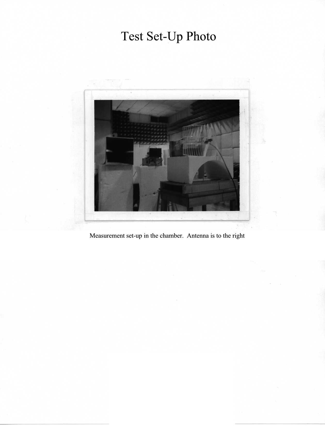
Document Text
Text extracted from the exhibit documents filed with the FCC. Open a document above to read the original.
Users Manual
Hyperlink Extended Range WLAN Kit Installation Manual Rev. A Page 1 Hyperlink Technologies, Inc. Hyperlink WaveLAN Extended Range Wireless LAN Kit Featuring Lucent Technologies WaveLAN Technology Installation Manual NOTE: The antenna system shall be installed ONLY by experienced antenna installers who are familiar with local building and safety codes, and wherever necessary have been licensed by appropriate government regulatory bodies. Failure to do so may void the Product Warranty, as well as expose the end-user to legal and/or financial liabilities. Hyperlink Technologies, its agents, resellers or distributors, are not liable for injury, damage, or violation of government regulations that may arise from failing to comply with the guidelines described in this document. Hyperlink Extended Range WLAN Kit Installation Manual Rev. A Page 2 Hyperlink Technologies, Inc. Disclaimer: The diagrams used in this manual are for illustrative purposes only. They should not be confused with the PC card operating in standalone mode. When these diagrams are used the PC card transceiver will be installed in conjunction with the specific DC Injector/Lightning Protector, Amplifier, cables and antennas listed in this manual. Copyright © 2000, Hyperlink Technologies, Inc.. All rights reserved. No part of the contents of this document may be transmitted or reproduced in any form or by any means without the written permission of Hyperlink Technologies, Inc. Portions Copyright © Lucent Technologies, Inc. All rights reserved HyperGain and HyperAmp are trademarks of Hyperlink Technologies, Inc. WaveLAN, WavePOINT and Orinoco are registered trademarks of Lucent Technologies, Inc. Hyperlink Extended Range WLAN Kit Installation Manual Rev. A Page 3 Hyperlink Technologies, Inc. Contents FCC Radio Interference Statement 4 Radiation and EIRP Information 5 Introduction 6 System Features 6 Types of Installations 7 System Requirements 8 Kit Contents 8 Tools Required 8 WaveLAN Card Features 8 Overall System Configuration 9 Antenna System Connection 10 Surveying the Antenna Site 10 Preparing for System Installation 11 Connections & Features of the Amplifier 12 The DC Power Injector/Lightning Protector 13 Mounting & Cabling the Amplified Antenna System 14 Installing the WaveLAN PC Card 16 Channel Settings 16 Basic System Checks 17 WaveLAN Antenna Alignment Diagnostics 17 System Specifications 18 APPENDICES Antenna Mounting Instructions Appendix A Hyperlink Extended Range WLAN Kit Installation Manual Rev. A Page 4 Hyperlink Technologies, Inc. USA- Federal Communications Commission (FCC) Interference Statement This device complies with Part 15 of the FCC Rules. Operation is subject to the following two conditions: (1) this device may not cause harmful interference, and (2) this device must accept any interference received, including interference that may cause undesired operation. Information to the user NOTE: This equipment has been tested and found to comply with the limits for a Class B digital device, pursuant to Part 15 of the FCC Rules. These limits are designed to provide reasonable protection against harmful interference in a residential installation. This equipment generates, uses, and can radiate radio frequency energy. If not installed and used in accordance with the instructions, it may cause harmful interference to radio communications. However, there is no guarantee that interference will not occur in a particular installation. If this equipment does cause harmful interference to radio or television reception, which can be determined by turning the equipment off and on, the user is encouraged to try and correct the interference by one or more of the following measures: • Reorient or relocate the receiving antenna. • Increase the distance between the equipment and the receiver. • Connect the equipment to an outlet on a circuit different from that to which the receiver is connected. • Consult the dealer or an experienced radio/TV technician for help. Any changes or modifications of equipment not expressly approved by the manufacturer could void the user’s authority to operate the equipment and the company’s warranty. NOTE: The antenna system shall be installed ONLY by experienced antenna installers who are familiar with local building and safety codes, and wherever necessary have been licensed by appropriate government regulatory bodies. Failure to do so may void the Product Warranty, as well as expose the end-user to legal and/or financial liabilities. Hyperlink Technologies, its agents, resellers or distributors, are not liable for injury, damage, or violation of government regulations that may arise from failing to comply with the guidelines described in this document. Hyperlink Extended Range WLAN Kit Installation Manual Rev. A Page 5 Hyperlink Technologies, Inc. Caution: Exposure to Radio Frequency Radiation. The radiated output power of this product is below the FCC radio exposure limits. Nevertheless, this product shall be used in such a manner that the potential for human contact during normal operation is minimized. Antenna shall be mounted in such a manner as to minimize the potential for human contact during normal operation. In order to avoid the possibility of exceeding the FCC radio frequency exposure limits, human proximity to the antenna shall not be less than 20 cm (8 inches) during normal operation. Hyperlink Technologies is not responsible for any radio or television interference caused by unauthorized modification of this device or the substitution or attachment of connecting cables and equipment other than specified by Hyperlink Technologies. The correction of interference caused by such unauthorized modification, substitution or attachment will be the responsibility of the user. Antenna Type Specified Antenna Gain (dBi) Maximum Output Power at Antenna Terminal (dBm) Total EIRP (dBm) Minimum RF Exposure Separation Distance (cm) HG2408P 7.5 24 31.5 10.6 HG2408U 8.0 24 32.0 11.2 HG2412P 12.0 20 …
Text truncated - open the document above for the full version.
Users Manual
FCC ID: MYF-WL2401 EXHIBIT: PLANNED STATEMENTS FOR MANUALS USA - Federal Communications Commission (FCC) Interference Statement This device compli es with Part 15 of the FCC Rules. Operation is subject to the following two conditions: (1) this device may not cause harmful interference, and (2) this device must accept any interference received, including interference that may cause undesired operation Information to the user NOTE: This equipment has been tested and found to comply with the limits for a Class B digital device, pursuant to Part 15 of the FCC Rules. These limits are designed to provide reasonable protection against harmful interference in a residential installation. This equipment generates, uses, and can radiate radio frequency energy. If not installed and used in accordance with the instructions, it may cause harmful interference to radio communications. However, there is no guarantee that interference will not occur in a particular installation. If this equipment does cause harmful interference to radio or television reception, which can be determined by turning the equipment off and on, the user is encouraged to try and correct the interference by one or more of the following measures: • Reorient or relocate the receiving antenna. • Increase the distance between the equipment and the receiver. • Connect the equipment to an outlet on a circuit different from that to which the receiver is connected. • Consult the dealer or an experienced radio/TV technician for help Caution: Exposure to Radio Frequency Radiation. The radiated output power of this product is below the FCC radio exposure limits. Nevertheless, this product shall be used in such a manner that the potential for human contact during normal operation is minimized. The following statement will be put in the product antenna manuals: “Caution: Exposure to Radio Frequency radiation. Antennae shall be mounted in such a manner to minimize the potential for human contact during normal operation. In order to avoid the possibility of exceeding the FCC radio frequency exposure limits, human proximity to the antenna shall not be less than 20 cm (8 inches) during normal operation.” Hyperlink Technologies is not responsible for any radio or television interference caused by unauthorized modification of the devices included with this IEEE 802.11 Wireless LAN Kit, or the substitution or attachment of connecting cables and equipment other than specified by Hyperlink Technologies. The correction of interference caused by such unauthorized modification, substitution or attachment wil l be the responsibility of the user.
Users Manual
Hyperlink Extended Range WLAN Kit Installation Manual Rev. A Page 1 Hyperlink Technologies, Inc. Hyperlink WaveLAN Extended Range Wireless LAN Kit Featuring Lucent Technologies WaveLAN Technology Installation Manual NOTE: The antenna system shall be installed ONLY by experienced antenna installers who are familiar with local building and safety codes, and wherever necessary have been licensed by appropriate government regulatory bodies. Failure to do so may void the Product Warranty, as well as expose the end-user to legal and/or financial liabilities. Hyperlink Technologies, its agents, resellers or distributors, are not liable for injury, damage, or violation of government regulations that may arise from failing to comply with the guidelines described in this document. Hyperlink Extended Range WLAN Kit Installation Manual Rev. A Page 2 Hyperlink Technologies, Inc. Disclaimer: The diagrams used in this manual are for illustrative purposes only. They should not be confused with the PC card operating in standalone mode. When these diagrams are used the PC card transceiver will be installed in conjunction with the specific DC Injector/Lightning Protector, Amplifier, cables and antennas listed in this manual. Copyright © 2000, Hyperlink Technologies, Inc.. All rights reserved. No part of the contents of this document may be transmitted or reproduced in any form or by any means without the written permission of Hyperlink Technologies, Inc. Portions Copyright © Lucent Technologies, Inc. All rights reserved HyperGain and HyperAmp are trademarks of Hyperlink Technologies, Inc. WaveLAN, WavePOINT and Orinoco are registered trademarks of Lucent Technologies, Inc. Hyperlink Extended Range WLAN Kit Installation Manual Rev. A Page 3 Hyperlink Technologies, Inc. Contents FCC Radio Interference Statement 4 Radiation and EIRP Information 5 Introduction 6 System Features 6 Types of Installations 7 System Requirements 8 Kit Contents 8 Tools Required 8 WaveLAN Card Features 8 Overall System Configuration 9 Antenna System Connection 10 Surveying the Antenna Site 10 Preparing for System Installation 11 Connections & Features of the Amplifier 12 The DC Power Injector/Lightning Protector 13 Mounting & Cabling the Amplified Antenna System 14 Installing the WaveLAN PC Card 16 Channel Settings 16 Basic System Checks 17 WaveLAN Antenna Alignment Diagnostics 17 System Specifications 18 APPENDICES Antenna Mounting Instructions Appendix A Hyperlink Extended Range WLAN Kit Installation Manual Rev. A Page 4 Hyperlink Technologies, Inc. USA- Federal Communications Commission (FCC) Interference Statement This device complies with Part 15 of the FCC Rules. Operation is subject to the following two conditions: (1) this device may not cause harmful interference, and (2) this device must accept any interference received, including interference that may cause undesired operation. Information to the user NOTE: This equipment has been tested and found to comply with the limits for a Class B digital device, pursuant to Part 15 of the FCC Rules. These limits are designed to provide reasonable protection against harmful interference in a residential installation. This equipment generates, uses, and can radiate radio frequency energy. If not installed and used in accordance with the instructions, it may cause harmful interference to radio communications. However, there is no guarantee that interference will not occur in a particular installation. If this equipment does cause harmful interference to radio or television reception, which can be determined by turning the equipment off and on, the user is encouraged to try and correct the interference by one or more of the following measures: • Reorient or relocate the receiving antenna. • Increase the distance between the equipment and the receiver. • Connect the equipment to an outlet on a circuit different from that to which the receiver is connected. • Consult the dealer or an experienced radio/TV technician for help. Any changes or modifications of equipment not expressly approved by the manufacturer could void the user’s authority to operate the equipment and the company’s warranty. NOTE: The antenna system shall be installed ONLY by experienced antenna installers who are familiar with local building and safety codes, and wherever necessary have been licensed by appropriate government regulatory bodies. Failure to do so may void the Product Warranty, as well as expose the end-user to legal and/or financial liabilities. Hyperlink Technologies, its agents, resellers or distributors, are not liable for injury, damage, or violation of government regulations that may arise from failing to comply with the guidelines described in this document. Hyperlink Extended Range WLAN Kit Installation Manual Rev. A Page 5 Hyperlink Technologies, Inc. Caution: Exposure to Radio Frequency Radiation. The radiated output power of this product is below the FCC radio exposure limits. Nevertheless, this product shall be used in such a manner that the potential for human contact during normal operation is minimized. Antenna shall be mounted in such a manner as to minimize the potential for human contact during normal operation. In order to avoid the possibility of exceeding the FCC radio frequency exposure limits, human proximity to the antenna shall not be less than 20 cm (8 inches) during normal operation. Hyperlink Technologies is not responsible for any radio or television interference caused by unauthorized modification of this device or the substitution or attachment of connecting cables and equipment other than specified by Hyperlink Technologies. The correction of interference caused by such unauthorized modification, substitution or attachment will be the responsibility of the user. Antenna Type Specified Antenna Gain (dBi) Maximum Output Power at Antenna Terminal (dBm) Total EIRP (dBm) Minimum RF Exposure Separation Distance (cm) HG2408P 7.5 24 31.5 10.6 HG2408U 8.0 24 32.0 11.2 HG2412P 12.0 20 …
Text truncated - open the document above for the full version.
Attestation Statements
To whom this may concern FCC ID: MYF-WL2401 Re: Compliance to Section 15.203 1. On the PC Card there will be a special non-standard connector, for connection to the external antenna system. This connector would comply with 15.203. 2. For use with outdoor antenna system components: • each outdoor antenna system component uses a standard N-type connector. • user will receive an adapter cable assembly to change from special connector to N-type connector in total cabling system. • with each outdoor antenna kit a manual/flyer will be shipped. This manual/flyer will contain the following warning: ”The antenna shall be installed ONLY by experienced antenna installers who are familiar with local building and safety codes, and wherever necessary have been licensed by appropriate government regulatory bodies. Failure to do so may void the Product Warranty, as well as expose the end-user to legal and/or financial liabilities. Hyperlink Technologies, its agents, resellers or distributors, are not liable for injury, damage, or violation of government regulations that may arise from failing to comply with the guidelines described in this document.” In the manual that comes with each system there will be a general warning on external antennae: “This product may only be connected to certified Hyperlink Technologies antennae. Using other antennae will void warranty and may cause degradation of system performance. Outdoor antennae must be professionally installed complying with the certified antennae and cable kits. The use of unauthorized antennae violates the country’s law or regulations. Hyperlink Technologies, its agents, resellers or distributors, are not liable for injury, damage, or violation of government regulations that may arise from failing to comply with the guidelines described in this document.”
Block Diagram
SYSTEM BLOCK DIAGRAM FCC ID: MYF-WL2401 HYPERLINK TECHNOLOGIES, INC. The overall system configuration is shown below: DC INJECTOR BLOCK DIAGRAM FCC ID: MYF-WL2401 HYPERLINK TECHNOLOGIES, INC. DC Injector Model BT2404 FROM PC CARDTO ANTENNA RFRF and DC POWER DC FROM POWER SUPPLY TRANSMIT POWER SENSING INPUT ATTENUATOR (FACTORY CONFIGURABLE T/R SWITCH CONTROL RECEIVE LNABANDPASS FILTER TRANSMIT POWER AMPLIFIER T/R SWITCH T/R SWITCH TO / FROM RADIO TO / FROM ANTENNA AMPLIFIER BLOCK DIAGRAM FCC ID: MYF-WL2401 HYPERLINK TECHNOLOGIES, INC. Amplifier Model HA2401
Cover Letter(s)
1201 Clint Moore Road Boca Raton, FL 33487 USA Tel: 561-995-2256 Fax: 561-995-2432 Federal Communications Commission Equipment Approval Services PO Box 358315 Pittsburgh, PA 15251-5315 May 12, 2000 Re: Certification of Hyperlink Technologies Extended Range Wireless LAN FCC ID MYF-WL2401 Dear Sir/Madam, Please find enclosed FCC Application Form 731 and corresponding documentation for the certification of the Hyperlink Technologies Extended Range Wireless LAN product. It concerns a basic PC Card DSSS radio modem and outdoor power amplifier unit which can be used with any of eight (8) possible antennae: Omni-Directional: 8 dBi and 15 dBi gain, Vertical Polarized Directional Panel: 7.5 dBi and 12 dBi gain, Vertical/Horizontal Polarized Directional Yagi: 14.5 dBi gain Directional Grid: 15 dBi, 19 dBi and 23.5 dBi, Vertical/Horizontal Polarization These eight configurations are covered within a single test lab report. Sincerely, Peter Roth President Encl.
Cover Letter(s)
1201 Clint Moore Road Boca Raton, FL 33487 USA Tel: 561-995-2256 Fax: 561-995-2432 Federal Communications Commission Authorization and Evaluation Division 7435 Oakland Mills Road Columbia, MD 21046 May 12, 2000 Re: Request for Confidentiality for FCC ID MYF-WL2401 Dear Sir/Madam, Pursuant to 47 CFR 0.457(d) and O/459 we hereby request confidentiality status of Hyperlink Technologies Documents SCH-HA2401 and SCH-BT2404 and Lucent Technologies Document 011682 (schematic diagrams used in this application). It concerns pdf files: SCH-HA2401, SCH-BT2404, 0116822, 0116823, 0116824, 0116825, 0116826 and 0116827) Sincerely, Peter Roth President Encl.
Cover Letter(s)
1201 Clint Moore Road Boca Raton, FL 33487 USA Tel: 561-995-2256 Fax: 561-995-2432 Federal Communications Commission Equipment Approval Services PO Box 358315 Pittsburgh, PA 15251-5315 May 12, 2000 Re: Certification of Hyperlink Technologies Extended Range Wireless LAN FCC ID MYF-WL2401 Dear Sir/Madam, When filling out form 731 on-line I neglected to enter an email address for the technical correspondence. My contact information is as follows: Peter Roth Email: [email protected] Tel: 561-995-2256 Fax: 56-995-2432 I apologize for any inconvenience this may have caused. Sincerely, Peter Roth President
ID Label/Location Info
Photo No. A1 FCC ID: MYF-WL2401 Bottom view of RF-modem (without label) Label below, in reduced size will be put on this side of the product. Made in Taiwan 010649/A S/N: xxxxxxxxxxxx T/N: xxxxxxxx P/N: 010yyy/ x FCC ID: MYF-WL2401 MAC address: xxxxxxxxxxxx Hyperlink Technologies PC24E-H-FC S/N number in Barcode
Operational Description
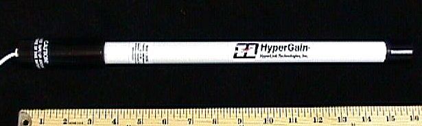
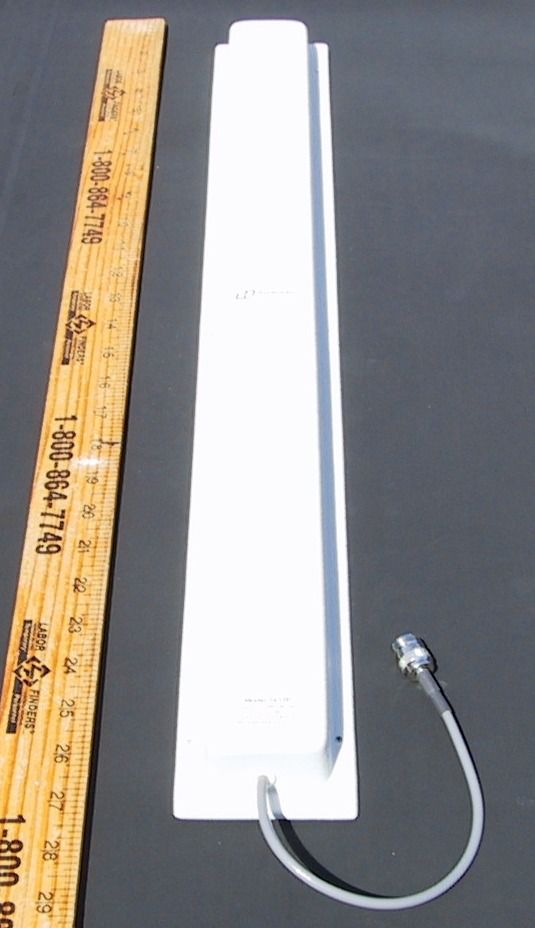
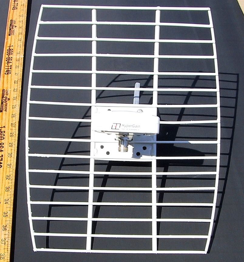
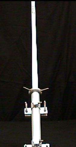
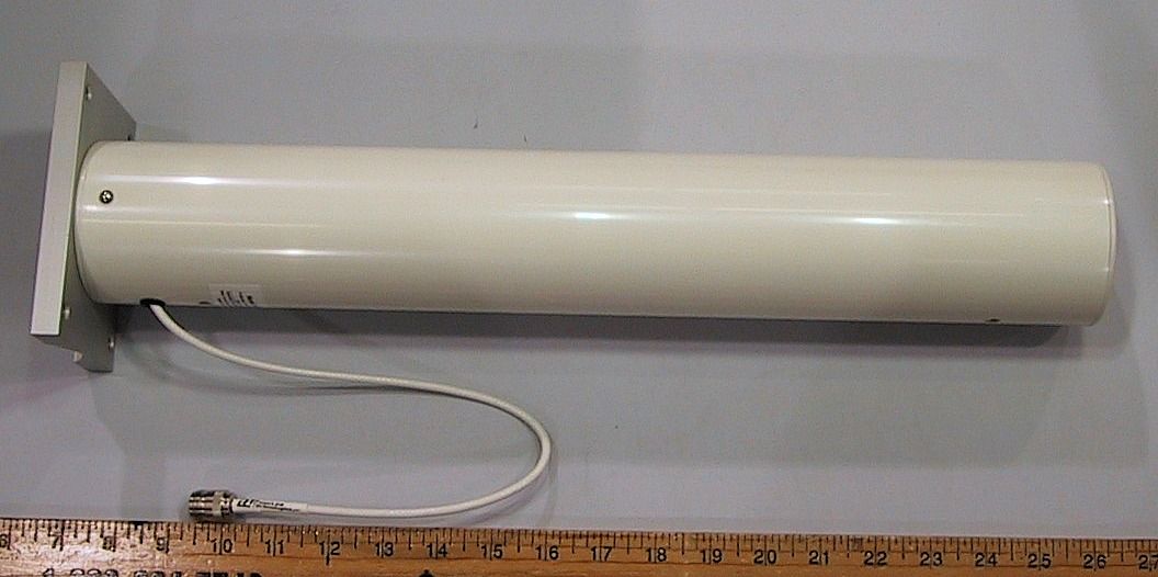
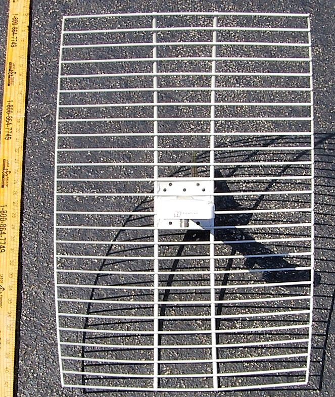
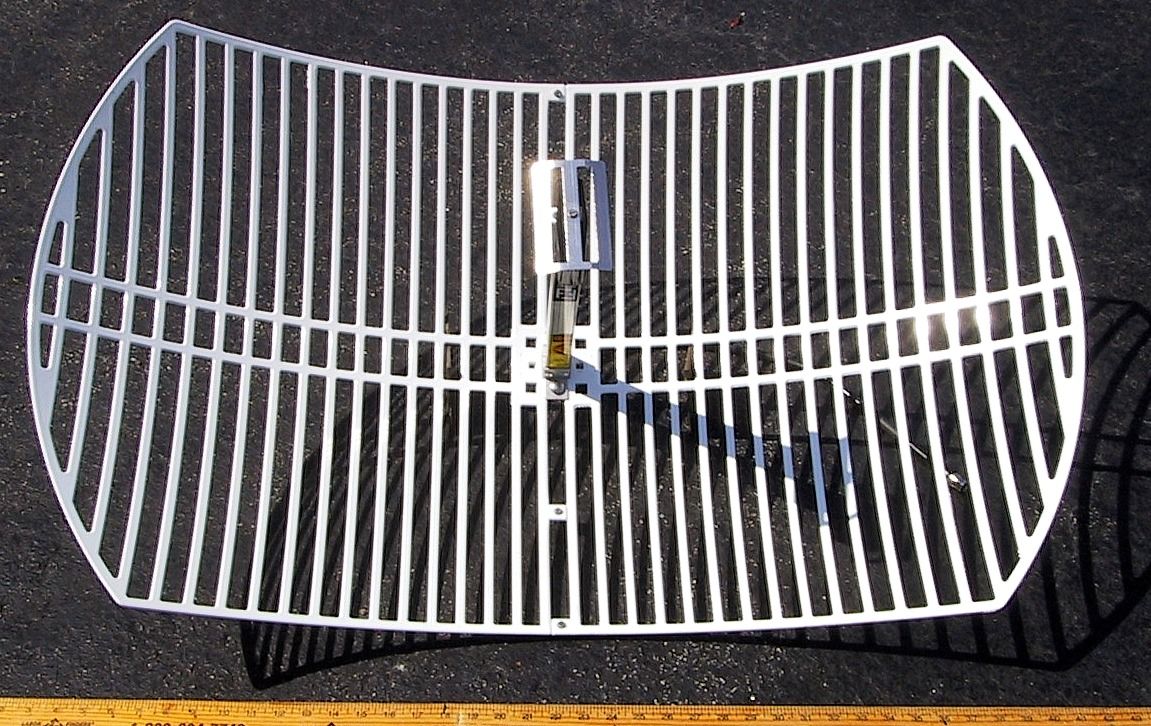
Hyperlink Extended Range Wireless LAN Kit FCC ID: MYF-WL2401 Product Description Introduction The Hyperlink Extended Range Wireless LAN Kit is a direct sequence spread spectrum wireless transceiver providing 11 Mbit/sec data rate to support wireless connections in an IEEE 802.3 LAN. Equipped with a Hyperlink Extended Range Amplified Antenna System, this product offers a high-performance long-range building-to-building wireless networking solution. This kit incorporates Lucent Technologies WaveLAN technology. WaveLAN uses a state-of-the-art direct sequence spread spectrum technology to implement robust 11 Mbps transmission, and offers true “Plug and Play” installation. System Features: This system has the following features: • IEEE 802.11 Compatibility. • Wireless 11 Mbps data rate. • State-of-the-art spread spectrum technology provides reliable, secure, long range, radio link operation. • True “Plug and Play” installation for compatibility with all 802.3 and Ethernet II LAN devices, all operating systems and all protocol stacks. • PCMCIA Form Factor • Seven (7) user-selectable channels of operation. • Remote mounted bi-directional amplifier to optimize transmit power and eliminate the effects of system cable losses. System Contents: Each system contains the following items: WaveLAN/Orinoco Turbo 11 Mbit IEEE 802.11 PC Card HyperAmp Remote Mounted Amplifier HyperGain Antenna (Omni, Yagi, Panel or Grid) HyperGain DC Power Injector/Lightning Protector 50 ft. Antenna Cable 0.5 meter Jumper Cable Mounting Hardware Manual Overall System Configuration The overall system configuration is shown below. WaveLAN PC Card Adapter Cable 0.5 meter DC Power Injector Antenna Cable 50ft. Antenna Network Workstation, WavePOINT-II Processor or other Bridge Unit Amplifier DC Power Supply Antennas The system is available with one of eight possible antennas: Antenna Type Specified Antenna Gain (dBi) Antenna Description Antenna Type HG2408P 7.5 Panel (patch) Directional HG2408U 8.0 Co-linear Omni Omni-directional HG2412P 12.0 Panel (patch array) Directional HG2415Y 14.5 Radome Yagi Directional HG2415U 15.0 Co-linear Omni Omni-directional HG2415G 15.0 Grid Directional HG2419G 19.0 Grid Directional HG2424G 23.5 Grid Directional Amplifier and DC Power Injector The amplifier included with the system is a linear, high-speed half-duplex bi- directional amplifier which provides final-stage transmit power amplification as well as a low-noise receive LNA which compensates for feed-cable attenuation. The DC Power Injector (also known as a "Bias-T") is an in-line device which couples DC power onto a coaxial cable, enabling the cable to carry both RF (radio frequency) signals and DC power. The amplifier is mounted outdoors at the antenna’s feed-point. It is powered remotely through the coaxial antenna feed cable by the way of the DC Power Injector. The DC Power Injector included with the kit also provides integral lightning protection. Amplifier Power Levels and System EIRP The amplifier peak power level is factory configured as follows: Antenna Type Specified Antenna Gain (dBi) Maximum Output Power at Antenna Terminal (dBm) Total EIRP (dBm) HG2408P 7.5 24 31.5 HG2408U 8.0 24 32.0 HG2412P 12.0 20 32.2 HG2415Y 14.5 20 34.7 HG2415U 15.0 20 35.2 HG2415G 15.0 20 35.2 HG2419G 19.0 17 36.0 HG2424G 23.5 11 35.1 Operating Frequency / Channel Settings The Hyperlink Extended Range WaveLAN System operates in seven (7) different operating frequency channels. These seven channels are a sub-set of the eleven standard IEEE 802.11 channels. NOTE: This equipment is not authorized for and may not be operated on IEEE channels 1, 2, 10, and 11. If the user wishes to interoperate with other IEEE 802.11 WaveLAN-compatible equipment he must set that equipment to one of the seven channels (A-G) shown in the table below: Channel Corresponding IEEE 802.11 Channel Channel Center Frequency NOT USED 1 2412 NOT USED 2 2417 A 3 2422 B 4 2427 C 5 2432 D 6 2437 E 7 2442 F 8 2447 G 9 2452 NOT USED 10 2457 NOT USED 11 2462 This WAVELAN IEEE PC Card product provides a WaveLAN compatible wireless connection for portable and mobile computers in accordance with IEEE standard 802.11 DSSS. It can work at 11, 5.5 2 or 1 Mbps. The operation is in accordance with IEEE 802.11. The product contains the foll owing blocks: - PCMCIA interface - Wireless Medium Access Control (WMAC); this chip is used for handshaking with the PCMCIA bus and for handling the IEEE protocol; it also does frequency management and interfaces to FlashROM for parameters on frequencies and Call codes. Here also selection for 11, 5.5, 2 or 1 Mbps is handled. - Digital signal processor takes care of all modulation/demodulation for DSSS for all above rates and can do selection out of 2 receiving antennae - Antenna function, provides connection to external antenna. Optionally it can be equipped with: - a factory installable data encryption feature (WEP), and - a BootROM for diskless workstation. Block Diagram PCMCIA Interface Connector The technical specification is as follows on the next page. Antenna Conn . WMAC DIGITAL SIGNAL PROCESSOR Hyperlink 11 Mbit/sec Outdoor Wireless LAN Kit 2.4 GHz Data Signalling Rate:11 , 5.5, 2 or 1 Mbit/s Media Access Protocol:According to IEEE 802.11 DSSS, CSMA/CA (Collision Avoidance) Bit Error Rate:Better than 10-8 Base-Band Modulation:- 2 Mbps: Differential Quadrature Phase Shift (before spreading) Keying (DQPSK) 2 bits/symbol - 11 and 5.5 Mbps: Complementary Code Keying Differential Quadrature Phase Shift Keying (DQPSK CCK) Spread Spectrum:Direct Sequence with 11 chips/symbol interval. Pseudo random Barker code sequence: { 1 -1 1 1 -1 1 1 1 -1 -1 -1 } Chipping Rate: 11 Mchips/s Carr ier Frequency Selectable from factory pre-programmed set which is a sub-set of the channels specified by IEEE 802.11: 2422, 2427, 2432, 2437, 2442, 2447, 2452 Peak Output Power 250 mW rms power (24 dBm) Antenna (indoor):e.g. Range Extender AIN24-OD-0202: - Gain 0 dBi - Polarization dive…
Text truncated - open the document above for the full version.
Operational Description
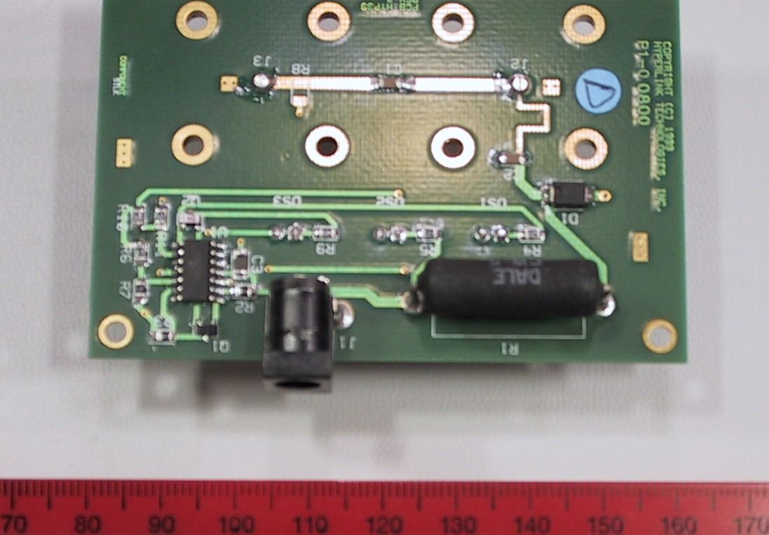
FCC ID: MYF-WL2401 BLOCK DIAGRAM DESCRIPTIONS Overall System The overall system is comprised of the following basic components: WaveLAN PC Card Radio 0.5 meter Jumper Cable DC Injector/Lightning Protector 50 foot Cable Amplifier Antenna The block first diagram shows the connection of the above system components. The PC Card radio is connected to the “TO RADIO” connector of the DJ Injector by way of the 0.5 meter jumper cable. The DC Power Supply is connected to the “12 VDC” connection on the DC Injector. The DC Injector then supplies both the RF signal as well as DC power to the Amplifier by way of the 50 foot cable. The Antenna is connected to the Amplifier’s “TO ANTENNA” connector. Each of the system components is described in the detailed block diagrams which follow. Block diagram description of the Lucent WaveLAN PC Card 2.4GHz, High Speed 1 WaveLAN PC Card 2.4 GHz High Speed DESCRIPTION OF THE BLOCK DIAGRAM The various parts of the Block diagram are numbered and an explanation is given of these blocks. First the transmitter will be described: A) Digital Signal Processor. (22) Function : Generate spreaded signal with an Barker sequence of 11, the original raw data rate of 1, 2, 5.5 or 11 Megabits is transformed to a symbol rate of one MegaBaud and multiplied with eleven and modulated with a DQPSK ( Differential Quadrature Phase Shift Keying ) Modulation for 1 and 2 Mbps or DQPSKCCK (CCK = Complementary Code Keying) for 5.5 and 11 Mbps. The unfiltered data comes out of I and Q and goes to the up/down mixer (6) B) The above signals are mixed in (6) in a so called quadrature modulator with the Intermediate Frequency ( IF) of 352 MHz. C) The upmixer is fed by the VCO of 704 MHz, which is divided by 2 to 352 MHz. D) The SAW ( 8 ) filters all unwanted mixing products, such that only the 352 MHz band remains. E) This signal goes into the RF upmixer ( 9) SA2420 were it is mixed with the RF VCO with a range of 2050 to 2150 MHz. F) The Rx/Tx switch (17) brings the signal to the variable attenuator (10 ), where the output level is controlled. G) The signal is fed through a 2.4- 2.5 GHz bandpass filter (11) to remove all unwanted mixer products, and thus to get a clean signal for further processing. H) The signal is amplified in (12), with approx 23 dB to an output level of approx. 15 dBm I) This signal goes to the RX/TX antenna (23/24) via the special connector with a switch inside to disable the antenna. J) The output power is controlled with a so called power feed back loop (15) in which the output power is compared with a DAC value from (10) Receiver functions. K) The receive signal enters the antenna passes the RX/TX switch (14) and (13) this is set to RX mode. L) The signal goes through the 2.4 GHz filter (16) to remove all unwanted spectral components in order to deliver a clean signal for the receiver. M) A Low Noise Amplifiers (LNA) (in 9) is used to amplify the weak signal to a level fitted for down mixing. N) The AGC (27) can amplify or attenuate the signal according to the Digital signal processor required input with a step size of 26 dB. O) Again the Rx/Tx switch in the Rx mode is passed and also the same filter as in transmit mode ( 18). P) The down mixer (9) mixes the 2.4 GHz with the 2.1 GHz to the 352 MHz IF. Q) The signal of 352 MHz is amplified again (9) and filtered by a SAW filter (19) to give a clean signal for the second mixer. Block diagram description of the Lucent WaveLAN PC Card 2.4GHz, High Speed 2 R) The Downmixer (6) mixes the 352 MHz signal down to the I and Q signals, also the auto gain control can increase the level to the required level via line 20. S) The very low amplitude baseband I and Q signal is amplified in the AMPs (6) to a level fitted for the Analog to Digital converters (22), which make it a proper signal for the digital signal processor. T) The digital signal processor (22) removes the spreading as present on the signal with a so called autocorrelation function. The resulting output of the processor is a received data rate of 1, 2, 5.5 or 11 Megabits. VCO , PLL and OSC. U) These three form one entity to generate a single tone signal for down mixing. There are two of these blocks available, one for the IF LO (7 and 6 ) (352MHz ) and one for the RF LO (25 and 26) of 2050 to 2150 MHz. V) All the PLL’s and the processor (2) have one reference Crystal of 22 MHz (4) with an accuracy of 25 ppm. General circuits: W) Antenna Diversity. This fu…
Text truncated - open the document above for the full version.
Contact Information
Applicant
Kenneth Burgner(Product Manager)
Test Firm
University of MichiganValdis Liepa
Technical Specifications
| # | Rule Parts | Frequency Range | Power Output | Tolerance |
|---|---|---|---|---|
| 1 | 15C | 2.42 GHz - 2.45 GHz | 250.00 mW | ppm |
Other Applications from L-Com, Inc.
MYF-LCUSB2415
Aug 17, 20142.4 GHz 802.11n Wireless USB Adapter
Equipment Class
DTS - Digital Transmission System
MYF-LCUSB
Apr 26, 2010802.11b/g USB Dongle with Amplifier
Equipment Class
DTS - Digital Transmission System
MYF-LCUSBX
Apr 15, 2010802.11b/g USB Dongle with Amplifier
Equipment Class
DTS - Digital Transmission System
MYF-XI-325
May 25, 2004Spread Spectrum Transmission System
Equipment Class
DTS - Digital Transmission System
MYF-XI-325X
May 16, 2004Spread Spectrum Transmission System
Equipment Class
DTS - Digital Transmission System