N293296Base Station for Wireless Microphone
Emkay Innovative Products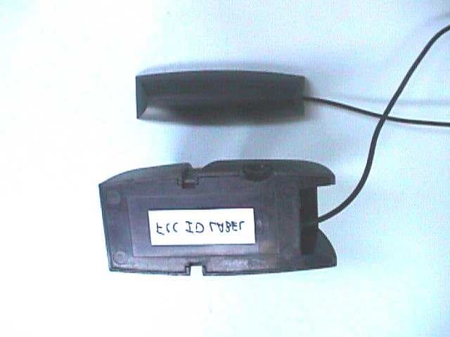
Click to zoom
Application Details
- Equipment Class
- JBP - Part 15 Class B Computing Device Peripheral
- Date of Grant
- Oct 12, 1998
- Application Purpose
- Original Equipment
- Date of Application
- Aug 30, 1998
- Equipment Note
- Base Station for Wireless Microphone
- Company
- Emkay Innovative Products
- Country
- United States
Documents & Files
Document Text
Text extracted from the exhibit documents filed with the FCC. Open a document above to read the original.
Block Diagram
GEL Report File PE9806Block DiagramFCC ID N293296 Glen Ellen Laboratories1August 28, 1998 Block Diagram of Base Station
External Photos
GEL Report File PE9806External PhotosFCC ID N293296 Glen Ellen Laboratories1August 28, 1998 View of the Assembled Base Station Unit with Attached Magnetic Transmitter Antenna All plastic parts are un-plated. GEL Report File PE9806External PhotosFCC ID N293296 Glen Ellen Laboratories2August 28, 1998 View of the Power Supply, Audio Cable, and Monitor Sense Cable GEL Report File PE9806External PhotosFCC ID N293296 Glen Ellen Laboratories3August 28, 1998 View of the Bottom of the Unit
ID Label/Location Info
GEL Report File PE9806ID Label/Location InfoFCC ID N293296 Glen Ellen Laboratories1August 28, 1998 ID Label/Location Information The following is a drawing of the bottom of the base station showing the FCC ID label and the FCC ID label location. The following is a drawing of the side of the headset showing the FCC ID label and the FCC ID label location. The FCC warning text appears in a prominent location in the manual as the product is too small to accommodate the text. FCC I.D. N29 3296 Model # RF-3296 FCC 90.265 Channel A Note: FCC Rules Part 15, Subpart A, 15.19(a)(1). This device complies with Part 15 of the FCC Rules. Operation is subject to the condition that this device does not cause harmful interference .
Internal Photos
GEL Report File PE9806Internal PhotosFCC ID N293296 Glen Ellen Laboratories1August 28, 1998 View of the Assembled Base Station Unit with Attached Magnetic Transmitter Antenna (All plastic parts are un-plated, and are not shown in the following photographs.) GEL Report File PE9806Internal PhotosFCC ID N293296 Glen Ellen Laboratories2August 28, 1998 View of the Base Station with Top Cover Removed, Showing Assembled PC Boards, With Receiver Board on Top, and Magnetic Transmitter Board on Bottom GEL Report File PE9806Internal PhotosFCC ID N293296 Glen Ellen Laboratories3August 28, 1998 View of the Front Side of the PC Boards GEL Report File PE9806Internal PhotosFCC ID N293296 Glen Ellen Laboratories4August 28, 1998 View of the Back Side of the PC Boards
Operational Description
GEL Report File PE9806Operational DescriptionFCC ID N293296 Glen Ellen Laboratories1August 28, 1998 Theory of Operation of Base Station Theory of Operation, Magnetic Transmitter Power supply. Unregulated DC voltage is delivered to the magnetic transmitter PCB assembly via J2. Pin 2 delivers approximately 16 VDC. Voltage regulation is accomplished with U11 (+12VDC) and U12 (+5VDC). The +5VDC supply (VCC) is used by the audio amplifier, TVM modulator and all logic circuits. The +12VDC supply (VCC2) is used by the power amplifier. Audio input amplifier. The input amplifier consists of L1, C27-C29, R1-R5 and U5A. The system is designed to accept the line output signal from a computer sound board with an expected level of between 100 mV and 1V rms. R5 can be adjusted for desired volume level. CR3 provides peak clipping to prevent over modulation of the TVM signal. The gain of the audio amplifier is set for a maximum of 1/5. This scales down the level of the input signal to that required by the TVM modulator chip U10. TVM modulator. Time variant modulation (TVM) is accomplished by U10 (JV242). This proprietary integrated circuit takes an audio input at pin 17, a 200kHz input at pin 24 and produces a TVM modulated signal at pin 14. For a complete explanation of the JV242 please refer to the attached chip specification. 200 kHz clock. A 200 kHz square wave is produced by U6 (XC303). The output frequency of this IC can also be set to 400 kHz by setting a jumper at JP1. Monitor sync circuit. Magnetic fields from horizontal sync coils in computer monitors can cause heterodyne tones in the magnetic receivers recovered audio. To eliminate this undesirable tone, a circuit has been added to lock the TVM clock to a harmonic of the computer monitors horizontal sync signal. An external pickup coil L4 is plugged into J1. The external coil is placed on the side of the computer monitor and inductively picks up the horizontal sync signals from the control yoke of the monitor. A high gain amplifier consisting of U1B, R13-R17, C33-C37, CR1, L2 and L3 amplifies and squares the sync signal. A low pass filter consisting of U1A, R18-R21 and C37- C39 removes any undesired high frequency components. A one-shot consisting of U2A, R28 and C42 limits the detected sync frequency to around 40 kHz. A phase locked loop consisting of U3, U4, R29-R34, C44 and C45 then multiplies the detected frequency by 10 to between 150 kHz and 400 kHz. A detector consisting of CR2, C41 R25-R27 and U5B senses the presence of a signal induced at the pickup coil and switches the clock source via U7 to either the fixed 200 kHz clock or the phase locked monitor sync clock source. Transmit coil power amp. P and N channel FETs Q1-Q4 are arranged in an H-bridge configuration Each side of the bridge is driven with complimentary signal delivered from the JV242 TVM modulator IC. Low pass filter capacitors C47-C50 are placed between source and drain of each FET to lower harmonic content of output drive signal. Filters consisting of C21-C26 and H2-H3 are used to reduce switching noise on power supply lines. November 25, 1997 GEL Report File PE9806Operational DescriptionFCC ID N293296 Glen Ellen Laboratories2August 28, 1998 Theory of Operation, Base Station Receiver Introduction: The following theory of operation describes in detail how the Base Station Receiver functions. Please refer to the Base Station Receiver System Block Diagram when reading this document. Antenna: The antenna is a helical type wound on a 1/4 by 20 nylon thread stock. The helical antenna is operating in the normal mode and therefore has similar performance to a 1/2 lambda end fed dipole. Input Match: This circuit is used to match the antenna to the low noise amplifier. The match steps up the impedence from 50 ohms to 500 ohms by means of a capacitor tap. One of the capacitors is adjustable. The adjustment of this capacitor is usually performed in conjunction with the two adjustments in the preselector filter when setting the front end gain and filter response. LNA: The low noise amplifier is a dual gate MESFET manufactured by NEC. The amplifier configuration is common source. This device provides excellent gain and the noise figure is about 3dB. Preselector Filter: The preselector is a 2 pole coupled resonator type. There are two capacitor adjustments in the filter to optimize the band pass response. This filter, in conjunction with the input matching filter, provides a 3 pole band pass response for the front end of the receiver. The bandwidth of this filter is around 4 MHz (169 MHz to 173 MHz). Local Oscillator: The reciever local oscillator uses a Butler topology. This configuration was chosen because it works well with overtone cut cyrstals. The crystal used for this oscillator is cut for series resonance at the channel frequency minus 10.7 MHz.. There is an adjustable inductor which is used to trim the oscillator on the exact frequency. Mixer: The signal on the output of the preselector and the local oscillator are combined in the mixer to create the I.F. at 10.7 MHz. The mixer is part of the FM Receiver I.C. (Motorola MC13156). The mixer is a double balanced active type using the Gilbert Cell topology. The mixer also provides a small amount of I.F. gain GEL Report File PE9806Operational DescriptionFCC ID N293296 Glen Ellen Laboratories3August 28, 1998 10.7 MHz I.F.: The next four stages after the mixer provide all the IF filtering and gain functions before audio detection. The output of the mixer is connected to a two element ceramic filter centered at 10.7 MHz. The bandwidth of the filter is 110 kHz.. The output of the filter is connected to an IF Amplifier in the MC13156. This amplifier then feeds another ceramic filter for further IF shaping. The output of this filter is connected to the limiting amplifier inside the MC13156 where the signal is compressed before detection. The main function of the entire I.F. chain is to establish the receiver’s operating bandwidth, system…
Text truncated - open the document above for the full version.
Test Report
TEST REPORT FOR FCC PART 15 COMPLIANCE FOR KNOWLES ELECTRONICS, INC. Prepared by Daniel C. Swann August 28, 1998 Knowles Electronics, Inc. Model Number RF-3296 Analog Inductive Intentional Radiator FCC Part 15.209 FCC ID N293296 GEL Report File PE9806 GLEN ELLEN LABORATORIES 1876 London Ranch Road Glen Ellen, CA 95442 GEL Report File PE9806FCC ID N293296 Glen Ellen Laboratories2August 28, 1998 MEASUREMENT/TECHNICAL REPORT KNOWLES ELECTRONICS, INC. FCC ID N293296 This report concerns:An Original Grant Equipment type:FCC Part 15, Subpart C, Paragraph 15.209(a) Analog Inductive Intentional Radiator, and Receiver for FCC Part 90.265, Wireless Microphone Deferred grant requested:no Transition rules per 15.37:no Report prepared by:Daniel C. Swann Glen Ellen Laboratories 1876 London Ranch Road Glen Ellen, CA 95442 (707) 996-8533 (707) 996-2803 fax Report Certified By:Daniel C. Swann DateAugust 28, 1998 GEL Report File: PE9806 GEL Report File PE9806FCC ID N293296 Glen Ellen Laboratories3August 28, 1998 TABLE OF CONTENTS 1GENERAL INFORMATION 1.1 Product Description 1.2 Related Submittal or Grant 1.3 Tested System Details 1.4 Test Methodology 1.5 Test Facility 2 PRODUCT LABELING AND MANUAL STATEMENTS 2.1 Product Labeling 2.2 FCC Statements in User Manual 3 SYSTEM TEST CONFIGURATION 3.1 Justification 3.2 EUT Exercise Equipment and Software 3.3 Special Accessories 3.4 Equipment Modifications 3.5 Configuration of Tested System Figure 3.1Configuration of Tested System, Base Station 4 CONDUCTED EMISSIONS DATA 5 RADIATED EMISSIONS DATA 5.1 Intentional Radiated Emissions, Base Station 5.2 Unintentional Radiated Emissions, Base Station 5.3 Field Strength Calculations ATTACHMENTS ID Label/Location Info, External Photographs, Block Diagrams, Schematics, Test Setup Photographs, Users Manual, Internal Photographs, Operational Descriptions, Transmitter Schematics, Photographs Of Tested EUT GEL Report File PE9806FCC ID N293296 Glen Ellen Laboratories4August 28, 1998 1GENERAL INFORMATION 1.1Product Description The Knowles Electronics, Inc. High Performance Radio Frequency Wireless Headset Model Number RF-3296 is a headset/base station combination utilizing a pulse modulated magnetic induction loop operating at 200 kHz or 400 kHz to transmit from the base station to the headset (FCC Part 15, Subpart C, Paragraph 15.209(a), intentional radiator), and a receiver for wireless microphone signals from a headset transmitter operating at 169.445 / 171.905 MHz. The product consists of a headset, a base station, a magnetic transmit antenna connected to the base station with a non-removable shielded cable, a computer monitor sensor (to sense nearby computer display frequencies to reduce interference,) an audio cable, and a wall mount power supply to power the base station. The base station provides a 7 mA charger position for the headset when the EUT is not in use. All plastic parts in the base station are un-plated. 1.2Related Submittal or Grant There are no related submittals or grants. GEL Report File PE9806FCC ID N293296 Glen Ellen Laboratories5August 28, 1998 1.3Tested System Details EUT Knowles Electronics, Inc. Model Number RF-3296. Made by: Knowles Electronics, Inc. 2800 West Golf Road Rolling Meadows, IL 60143 See the Block Diagram/Operational Description for more information. 1.4Test Methodology The conducted and radiated tests were performed in accordance with the ANSI C63.4-1992 standard. See Figure 3.1 and the photographs for details of the test setup. The base station unit was tested with a laptop computer, a serial device (mouse) and a parallel device (printer.) 1.5Test Facility The Glen Ellen Laboratories open area test site and conducted measurement facility is located in Glen Ellen, California, at the street address of 1876 London Ranch Road. This site has been fully described in a report dated September 16, 1996, submitted to the FCC, and accepted in a letter dated December 4, 1996 (31040/SIT/1300F2.) Test equipment used was: 1.Hewlett Packard 8560A opt 002 spectrum analyzer, cal due 6-06-99. 2.Sonoma Instruments 330 opt 38 preamplifier, 10 kHz to 2.5 GHz, cal due 3-06-99. 3.GEL BIC9414 biconical antenna, 30 MHz to 300 MHz, cal due 6-13-99. 4.GEL LPA-3 log periodic antenna, 275 MHz to 2 GHz, cal due 6-13-99. 5.GEL ML9411 passive magnetic loop antenna, 10 kHz to 30 MHz, cal due 2-22-99. 6.EMCO LISN, model number 3825/2, cal due 4-25-99. 7.EMCO LISN, model number 3825/2, cal due 7-29-99. GEL Report File PE9806FCC ID N293296 Glen Ellen Laboratories6August 28, 1998 2PRODUCT LABELING AND MANUAL STATEMENTS 2.1Product Labeling The following appears on the label: Note: FCC Rules Part 15, Subpart A, 15.19(a)(1). This device complies with Part 15 of the FCC Rules. Operation is subject to the condition that this device does not cause harmful interference. 2.2FCC Statement in User Manual The following statements appear in a prominent location in the text of the user manual: Note: This device complies with part 15 of the FCC Rules. Operation is subject to the following two conditions: (1) This device may not cause harmful interference, and (2) This device must accept any interference received, including interference that may cause undesirable operation. GEL Report File PE9806FCC ID N293296 Glen Ellen Laboratories7August 28, 1998 3SYSTEM TEST CONFIGURATION 3.1Justification The EUT was tested in accordance with the standard ANSI C63.4-1992, 47 CFR Part 15, Subpart C, and 47 CFR Part 90.265. The base station magnetic transmitter was tested at the two available transmit frequencies, 200 kHz and 400 kHz, changed by moving a jumper on the magnetic transmitter board. The base station receiver was tested at the lowest frequency available for Part 90.265 wireless microphones, 169.445 MHz, and the highest frequency available, 171.905 MHz. These frequencies correspond to a LO frequency of 158.745 MHz, and of 161.205 MHz, respectively. The receiver frequency was changed by changing the crystal in the unit. 3.2EUT Exercise Equipm…
Text truncated - open the document above for the full version.
Test Setup Photos
FCC ID: MXN-890 Test Report E23281.00Master Meter, Inc.Page 1 of 1 Aradmstr\scem2328 Schematics Schematics are regarded by the manufacturer as highly confidential. He would like to be exempted from this requirement, if possible. If necessary for the approval of this application, please notify us as soon as possible; and the schematics will be submitted. Our email address is: [email protected]
Contact Information
Applicant
Roger Davis(Project Manager)
Technical Contact
Test Firm
Glen Ellen LaboratoriesDaniel Swann
Technical Specifications
| # | Rule Parts | Frequency Range | Power Output |
|---|---|---|---|
| 1 | 15B | - | - |
Other Applications from Emkay Innovative Products
N29RF100
Oct 18, 1998Wireless Microphone Headset
Equipment Class
TNE - Licensed Non-Broadcast Transmitter Held to Ear