N29RF100Wireless Microphone Headset
Emkay Innovative Products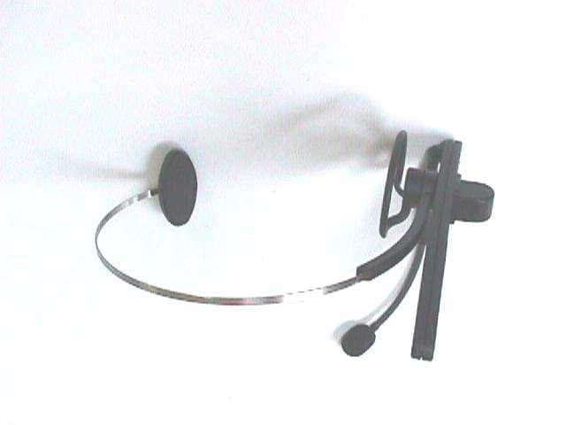
Click to zoom
Application Details
- Equipment Class
- TNE - Licensed Non-Broadcast Transmitter Held to Ear
- Date of Grant
- Oct 18, 1998
- Application Purpose
- Original Equipment
- Date of Application
- Aug 30, 1998
- Equipment Note
- Wireless Microphone Headset
- Frequency Range
- 169.44500000 - 171.90500000
- Company
- Emkay Innovative Products
- Country
- United States
Documents & Files
Document Text
Text extracted from the exhibit documents filed with the FCC. Open a document above to read the original.
Block Diagram
GEL Report File PE9805Block DiagramFCC ID N29RF100 Glen Ellen Laboratories1August 25, 1998 Block Diagram of Headset Transmitter
External Photos
GEL Report File PE9805External PhotosFCC ID N29RF100 Glen Ellen Laboratories1August 25, 1998 View of Headset GEL Report File PE9805External PhotosFCC ID N29RF100 Glen Ellen Laboratories2August 25, 1998 View of Label Location on the Headset
ID Label/Location Info
FCC I.D. N29 RF100Model # RF-3296FCC 90.265 Channel
Operational Description
GEL Report File PE9805Operational DescriptionFCC ID N29RF100 Glen Ellen Laboratories1August 25, 1998 Theory of Operation of Headset Headset Transmitter Theory Of Operation Introduction: The following theory of operation describes in detail how the headset transmitter RF functions. Please refer to the Head Set Transmitter System Block Diagram when reading this document. Microphone Input: The microphone input is a noise canceling type. It is intended that the microphone be positioned with-in 1 inch of the mouth or so. Automatic Level Control: This circuit is designed to provide a constant audio output when the input is variable (soft vs loud speech). The component used is a Philips Semi-conductor NE578 compandor I.C. configured to provide ALC. The compression point is set at 50mV rms and the gain is 25 V/V. With these settings, some amplitude variations will be present at normal speech levels. Crystal Modulation: The output of the ALC is fed to a varactor diode. The changing audio characteristics change the capacitance of the diode which is connected to the crystal. This changing capacitance pulls the resonant frequency of the crystal. Crystal Oscillator / X5 Multiplier: The crystal oscillator for this circuit uses a colpitts topology. Incorporated into the circuit is a high frequency fundamental mode crystal. The collector of the oscillator is tuned to the 5th harmonic of the crystal. There is a capacitor adjustment to trim the oscillator to with in 5 kHz of the actual transmit frequency. Filter: The output of the oscillator is connected to the main filter block for the transmitter. The filter type is a 3 pole coupled resonator centered at the transmit frequency. This filter is optimized to provide as much suppression of the 2nd, 3rd, and 4th harmonics of the oscillator as possible and no attenuation of the 5th harmonic which is the transmitter frequency. Power Amplifier: This is the final gain stage for the transmitter. The amplifier is operating in the class A mode and the collector is tuned to the transmitter output frequency to reduce the amount of filtering required on the output. GEL Report File PE9805Operational DescriptionFCC ID N29RF100 Glen Ellen Laboratories2August 25, 1998 Filter: The output filter is a 1 pole coupled resonator type with antenna match. This circuit provides further harmonic suppression and isolation of the PA from the antenna. Antenna: The antenna is a helical type wound on a 1/4 by 20 nylon thread stock. The helical antenna is operating in the normal mode and therefore has similar performance to a 1/2 lambda end fed dipole.
Test Report
TEST REPORT FOR FCC PART 90 COMPLIANCE FOR KNOWLES ELECTRONICS, INC. Prepared by Daniel C. Swann August 25, 1998 Knowles Electronics, Inc. Model Number RF-3296 Wireless Headset Microphone FCC Part 90.265 FCC ID N29RF100 GEL Report File PE9805 GLEN ELLEN LABORATORIES 1876 London Ranch Road Glen Ellen, CA 95442 GEL Report File PE9805FCC ID N29RF100 Glen Ellen Laboratories2August 25 1998 MEASUREMENT/TECHNICAL REPORT KNOWLES ELECTRONICS, INC. FCC ID N29RF100 This report concerns:An Original Grant Equipment type:FCC Part 90.265, Wireless Microphone Deferred grant requested:no Transition rules per 15.37:no Report prepared by:Daniel C. Swann Glen Ellen Laboratories 1876 London Ranch Road Glen Ellen, CA 95442 (707) 996-8533 (707) 996-2803 fax Report Certified By:Daniel C. Swann DateAugust 25, 1998 GEL Report File: PE9805 GEL Report File PE9805FCC ID N29RF100 Glen Ellen Laboratories3August 25 1998 TABLE OF CONTENTS 1GENERAL INFORMATION 1.1 Product Description 1.2 Related Submittal or Grant 1.3 Tested System Details 1.4 Test Methodology 1.5 Test Facility 2 PRODUCT LABELING AND MANUAL STATEMENTS 2.1 Product Labeling 2.2 FCC Statements in User Manual 3 SYSTEM TEST CONFIGURATION 3.1 Justification 3.2 EUT Exercise Equipment and Software 3.3 Special Accessories 3.4 Equipment Modifications 3.5 Configuration of Tested System Figure 3.1Configuration of Tested System, Headset 4 CONDUCTED EMISSIONS DATA 5 RADIATED EMISSIONS DATA 5.1 Headset Effective Radiated Power and Frequency Stability 5.2 Headset Emission Bandwidths 5.3 Unintentional Radiated Emissions, Headset 5.4 Field Strength Calculations ATTACHMENTS ID Label/Location Info, External Photographs, Block Diagrams, Schematics, Test Setup Photographs, Users Manual, Internal Photographs, Operational Descriptions, Transmitter Schematics, Photographs Of Tested EUT GEL Report File PE9805FCC ID N29RF100 Glen Ellen Laboratories4August 25 1998 1GENERAL INFORMATION 1.1Product Description The Knowles Electronics, Inc. High Performance Radio Frequency Wireless Headset Model Number RF-3296 is wireless microphone headset transmitter to transmit microphone signals to the base station, operating at 169.445 / 171.905 MHz (FCC Part 90.265(b), intentional radiator). Signals are received by the headset at either 200 or 400 kHz, from a base station unit, Model Number RF-3296. The headset is powered by re-chargeable batteries. All plastic parts are un-plated. 1.2Related Submittal or Grant There are no related submittals or grants. GEL Report File PE9805FCC ID N29RF100 Glen Ellen Laboratories5August 25 1998 1.3Tested System Details EUT Knowles Electronics, Inc. Model Number RF-3296. Made by: Knowles Electronics, Inc. 2800 West Golf Road Rolling Meadows, IL 60143 See the Block Diagram/Operational Description for more information. 1.4Test Methodology The radiated tests were performed in accordance with the ANSI C63.4-1992 standard. See Figure 3.1 and the photographs for details of the test setup. 1.5Test Facility The Glen Ellen Laboratories open area test site and conducted measurement facility is located in Glen Ellen, California, at the street address of 1876 London Ranch Road. This site has been fully described in a report dated September 16, 1996, submitted to the FCC, and accepted in a letter dated December 4, 1996 (31040/SIT/1300F2.) Test equipment used was: 1.Hewlett Packard 8560A opt 002 spectrum analyzer, cal due 6-06-99. 2.Sonoma Instruments 330 opt 38 preamplifier, 10 kHz to 2.5 GHz, cal due 3-06-99. 3.GEL BIC9414 biconical antenna, 30 MHz to 300 MHz, cal due 6-13-99. 4.GEL LPA-3 log periodic antenna, 275 MHz to 2 GHz, cal due 6-13-99. GEL Report File PE9805FCC ID N29RF100 Glen Ellen Laboratories6August 25 1998 2PRODUCT LABELING AND MANUAL STATEMENTS 2.1Product Labeling For the headset, the text of the FCC warning normally placed on the label appears in a prominent location in the manual, as the product is too small to accommodate the text. 2.2FCC Statement in User Manual The following statements appear in a prominent location in the text of the user manual: This wireless microphone complies with Part 90 of FCC Rules. There are a total of eight frequencies available for this microphone, and the microphone you plan to use operates on one of these frequencies. You must get a license for the frequency you plan to use before you use the microphone. Whether this license is applicable depends on how you will use the microphone. Look in your local phone book for the nearest FCC office and contact them to get the necessary application. Note: This device complies with part 15 of the FCC Rules. Operation is subject to the following two conditions: (1) This device may not cause harmful interference, and (2) This device must accept any interference received, including interference that may cause undesirable operation. GEL Report File PE9805FCC ID N29RF100 Glen Ellen Laboratories7August 25 1998 3SYSTEM TEST CONFIGURATION 3.1Justification The EUT was tested in accordance with the standard ANSI C63.4-1992, 47 CFR Part 15, Subpart C, and 47 CFR Part 90.265. The headset transmitter was tested at the lowest frequency available for Part 90.265 wireless microphones, 169.445 MHz, and the highest frequency available, 171.905 MHz. The transmitter frequencies were changed by changing the crystal in the unit. 3.2EUT Exercise Equipment and Software The product was tested in the powered up condition, with the addition of external modulation for the occupied bandwidth test of the headset, as described in the occupied bandwidth test results. 3.3Special Accessories No special accessories were used. 3.4Equipment Modifications The inductor L7 in the headset was changed to 150 nH. GEL Report File PE9805FCC ID N29RF100 Glen Ellen Laboratories8August 25 1998 3.5Configuration of Tested System The headset was tested by placing it in the center of the tabletop, with the headset held vertically by a nonconductive foam block. The tabletop was rotated 360 degrees, and the antenna height was scanned from 1 …
Text truncated - open the document above for the full version.
Test Report
GENERAL INFORMATION REQUIRED FOR TYPE ACCEPTANCE The following information and data listed below is an addendum to the original submittal dated 8/31/98, FCC ID: N29RF100, Form 731 conformation # EA91595. This information is provided per the request of Correspondence # 3848. 2.983 (a,b,c)Emkay Innovative Products, Inc. will manufacture the RF100 in quantity for use under FCC RULES PART 90.265(b), Wireless Microphones. 2.983 (d)TECHNICAL DESCRIPTION (1)Type of Emission:46K0F3E Bn = 2M + 2DK M = 8000 D = 15kHz (Peak Deviation) K = 1 Bn = 16k + 2(15k)(1) = 46k ALLOWED AUTHORIZED BANDWIDTH = 54kHz. 90.265(b)(1). (2)Frequency Range: The eight operating frequencies as specified in Part 90.265 (b) beginning with 169.445MHz and ending with 171.905MHz. (3)Power Range and Controls: Unit has no controls. (4)Maximum Output Power Rating: 30μWatts into a 50 ohm resistive load. (5)DC Voltages and Current into Final Amplifier: Final Amplifier Characteristics: Power Supply:2.15 Volts regulated from 2.5 V Battery. Vce:1.75 Volts Ice:3.2mA 2.983(d)TECHNICAL DESCRIPTION (CONT.) (6)Function of Each Semiconductor Device: U1Microphone Amp / ALC AmpNE578D Y1Fundamental Mode Crystal CR1 Diode ReferenceMA4CP101A (6)Function of Each Semiconductor Device (Cont.): CR2 Modulation DiodeMA45438 Q1Oscillator TransistorMMBR931 Q2Output Amplifier TransistorAT30533 U4Voltage RegulatorLP2951CM U2Part of the Magnetic Receiver U3Part of the Magnetic Receiver (7)Complete Circuit Diagram: The schematic diagram is included as Exhibit A. The block diagram was included in the original submittal. Note: Component value changes are as follows: R3 to 6.8k, R24 to 110k, R11 to 15k and C12 to 2.2nF. (8)The INSTRUCTION MANUAL was included in the original submittal. (9)The TUNE-UP PROCEDURE is included as Exhibit B. (10)Description of all circuitry and devices provided for determining and stabilizing frequency. The transmitter frequency is controlled by a crystal. The crystal specification is included as Exhibit C. The crystal can be trimmed by adjusting C49. (11)Description of any circuits or devices employed for suppression of spurious radiation, for limiting modulation, and for limiting power. The circuitry is described in the Theory of Operation and was included in the original submittal. Suppression of Spurious Radiation: The circuitry between the collector of Q1 and the base of Q2 and the circuitry between the collector of Q2 and the Antenna are coupled resonator filters centered at the transmitter frequency and suppress all out of band harmonics. Limiting Modulation: The transmitter audio processing is contained in U1 and the external circuitry connected to U1. This IC is configured as an ALC circuit providing microphone gain and compression beyond a certain drive level. Limiting Power: There is no circuitry specifically included to limit power. Output power is limited by the collector current in Q2. (12)Digital Modulation: The unit does not employ digital modulation. 2.983 (e)The data required by 2.985 through 2.997 is submitted below. 2.985 (a)RF Power Output. RF Power is measured by connecting a 50 ohm cable to the output terminals of the transmitter and then connecting the other end of the cable to a Modulation Analyzer and selecting the RF Level Measurement. With an input voltage of 2.5 volts (battery voltage) and the transmitter frequency properly adjusted, the RF output measures: INPUT POWER:(1.75V)(0.0032A) = 5.6mWatts OUTPUT POWER: 15μWatts. Transmitter Under Test Power Supply (2.5 Volts) Modulation Analyzer HP8901A (50 Ohm Input) Coax Cable 2.987 (a)(b)Modulation Characteristics Audio Frequency Response / Modulation Limiting The audio frequency response was measured by injecting a swept audio into the microphone input terminals and measuring the output level at the modulation input to the RF Oscillator. An audio analyzer was used as the audio stimulus and measuring receiver. Audio Low Pass Filter The audio low pass filter is not required in this unit. Int, Scrn C & Device: Redirect: To Select by: Filename: RF100_A1 Auto Protect: Verify: Yes Set Remote Aux Set Remote Aux Page 2, Plotter B K 07-OCT-1998 13:07:07 Mode: SSR A: Frequency Response, Magn dB re 202002k20kHz -50 -40 -30 -20 -10 0 dB 1.0 mV Input 3.16 mV Input 10 mV Input 31.6 mV Input 100 mV Input FCC Part 2.987(a)(b)FCC ID N29RF100 Audio Bandwidth and Modulation Limiting Plot 2.989 (c) Occupied Bandwidth Data in the figures below show that all sidebands beyond the authorized bandwidth are less than 0.5% of the unmodulated carrier. The transmitter was modulated with a 2500Hz tone and was adjusted for 50% modulation plus 16dB. Un-modulated Carrier 2500 Hz, 50% +16dB Measurement Results:The figure above indicates that the unit meets the FCC requirement. The Emission bandwidth is approximately 40 kHz. Requirement:Part 90.265 (b)(1) Emission bandwidth of 54kHz or less. Transmitter Under Test Power Supply (2.5 Volts) Spectrum Analyzer HP8560A (50 Ohm Input) Coax Cable Audio Oscillator 2.991Spurious Emissions at the Antenna Terminals (Conducted) The following data shows the level of conducted spurious responses. The carrier was modulated in accordance with 2.989. The spectrum was scanned from 9 kHz to 2000 MHz. Requirement: Emissions must be 43 +10log(Po) dB below the mean power output of the transmitter. 43 + 10log(0.0003) = 8 dB conducted spurious emissions tests, Part 2.991 FrequencyMeasuredCableAmplifierSignal dB down MHzAmplitudeLossGainLevelfrom dBuVdBdBdBuVfundamental 171.90988.2 0.30.088.50.0 34.38117.3 0.10.017.471.2 68.76428.4 0.10.028.560.0 103.20335.2 0.20.035.453.1 137.50558.0 0.30.058.330.3 206.27355.9 0.40.056.332.2 240.68742.8 0.50.043.345.3 275.00736.0 0.60.036.652.0 343.79053.1 0.70.053.834.8 378.19123.8 0.80.024.664.0 412.57222.2 0.80.023.065.5 446.95319.2 0.90.020.168.4 481.33421.2 1.00.022.266.4 No emissions were present from 500 MHz to 2000 MHz. 2.993 (a)(b)Field Strength of Spurious Emissions Transmitter Under Test Spectrum Analyzer HP8560A (50 Ohm…
Text truncated - open the document above for the full version.
Test Setup Photos
GEL Report File PE9805Test SetupFCC ID N29RF100 Glen Ellen Laboratories1August 25, 1998 View of Front of Headset for Radiated Emissions GEL Report File PE9805Test SetupFCC ID N29RF100 Glen Ellen Laboratories2August 25, 1998 View of Back of Headset for Radiated Emissions
Contact Information
Applicant
Roger Davis(Project Manager)
Technical Contact
Phonic Ear, Inc.Roger Davis
[email protected]707-769-1110
3880 Cypress Dr. · Petaluma, California · United States
Test Firm
Glen Ellen LaboratoriesDaniel Swann
Technical Specifications
| # | Rule Parts | Frequency Range | Power Output | Emission | Tolerance |
|---|---|---|---|---|---|
| 1 | 90 | 169.445 MHz - 171.905 MHz | 30.00 µW | 46K0F3E | 10000.0000000000 Hz |
Other Applications from Emkay Innovative Products
N293296
Oct 12, 1998Base Station for Wireless Microphone
Equipment Class
JBP - Part 15 Class B Computing Device Peripheral