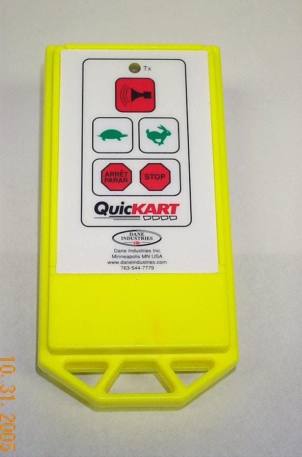
N2N600-041Remote Control for Electric Utility Machine
Dane Technologies, Inc.
Click to zoom
Application Details
- Equipment Class
- DSC - Part 15 Security/Remote Control Transmitter
- Date of Grant
- Aug 24, 2003
- Application Purpose
- Original Equipment
- Date of Application
- Aug 24, 2003
- Equipment Note
- Remote Control for Electric Utility Machine
- Frequency Range
- 433.98000000 - 433.98000000
- Company
- Dane Technologies, Inc.
- Country
- United States
Documents & Files
Document Text
Text extracted from the exhibit documents filed with the FCC. Open a document above to read the original.
Users Manual
QUICKART 2000 OWNER’S MANUAL OPERATING INSTRUCTIONS TRAINING MANUAL QUICKART ELECTRIC UTILITY MACHINE MANUFACTURED BY: DANE INDUSTRIES, INC. PHONE: 763-544-7779 5400 NATHAN LN. N., SUITE 150 TOLL FREE: 1-888-544-7779 PLYMOUTH, MN 55442 FAX: 763-544-4234 WWW.DANEINDUSTRIES.COM Part No. 970-005 Rev. Date: 8/21/03 DANE INDUSTRIES, INC. QUICKART 2000 OWNER’S MANUAL 5400 Nathan Lane N. , Suite 150, Plymouth, MN 55442 / 888-544-7779 / 763-544-7779 / Fax 763-544-4234 WWW.DANEINDUSTRIES.COM QUICKART 2000 OWNER’S MANUAL OPERATING INSTRUCTIONS TRAINING GUIDE TABLE OF CONTENTS TOPIC SECTION Owner’s Manual and Operating Instructions...................................1 Training Manual ..............................................................................2 Certified Operator’s Test .................................................................3 Note on radio equipment used: This device complies with part 15 of the FCC Rules. Operation is subject to the following two conditions: (1) This device may not cause harmful interference, and (2) This device must accept any interference received, including interference that may cause undesired operation. Note: This equipment has been tested and found to comply with the limits for a Class B digital device, pursuant to part 15 of the FCC Rules. These limits are designed to provide reasonable protection against harmful interference in a residential installation. This equipment generates, uses, and can radiate radio frequency energy and, if not installed and used in accordance with the instructions, may cause harmful interference to radio communications. However, there is no guarantee that interference will not occur in a particular installation. If this equipment does cause harmful interference to radio or television reception, which can be determined by turning the equipment off and on, the user is encouraged to try to correct the interference by one or more of the following measures: - Reorient or relocate the receiving antenna. - Increase the separation between the equipment and receiver. - Connect the equipment into an outlet on a circuit different from that which the receiver is connected. - Consult the dealer or an experienced radio/TV technician for help. The abbreviation IC, before the Canadian Registration Number signifies that registration was performed based on a Declaration of Conformity indicating that Industry Canada technical specifications were met. It does not imply that Industry Canada approved the equipment. The CE mark, if present, declares that this equipment meets relevant EU Directives and Standards. DANE INDUSTRIES, INC. QUICKART 2000 OWNER’S MANUAL 20 5400 Nathan Lane N. , Suite 150, Plymouth, MN 55442 / 888-544-7779 / 763-544-7779 / Fax 763-544-4234 WWW.DANEINDUSTRIES.COM ORIENTATION TO THE QUICKART 2000 MANUAL MODE: Manual Mode is defined as operating the QuicKart while walking behind the QuicKart 2000. Direction is controlled by the handle bar. Speed is controlled by turning the twist grip throttle. Direction is controlled by touching the touch pad switch located on the control panel. When the switch is pressed, the direction changes between forward and reverse as indicated by the direction light. REMOTE MODE : (See diagram on page 22.) Remote Mode is defined as operating the QuicKart with the remote control while standing or walking alongside the lead cart of the cart chain coupled to the QuicKart 2000. Steering is controlled by guiding the lead cart in the desired direction. Forward speed, brakes and horn are operated with the hand held radio remote control. While in remote mode, the QuicKart will only move forward. CONTROL PANEL: (See diagram on page 22.) At the top of the Control Panel are 5 lights which show the percent of remaining battery capacity (BATTERY CHARGE LEVEL). When the batteries are fully charged the light at the "100" mark will be lighted. As the QuicKart is used throughout the day, the lights will slowly change from 100 to 80, 60, and 40 until the light for 20 is lighted. The charging level is most accurately shown when the QuicKart is pushing carts. When the 20% capacity light starts to flash on and off, it means there are approximately 4 minutes of remaining power before the QuicKart automatically shuts down. If the QuicKart does shut down, turn the key off for a few minutes, then on again. This may allow time to reach the charging station. Recharge the batteries for at least 8 to 10 hours or until fully recharged. The control panel also includes a series of 4 lights and panel button switches with the following functions: The light labeled "MANUAL" is for manual operation and "RADIO" is for remote operation. The push button switch, just below these two lights, will toggle between manual and remote control. The QuicKart will automatically set to manual operation and forward whenever it is turned on. It cannot be moved from manual to remote operation when the QuicKart is moving, only when it is stopped. DANE INDUSTRIES, INC. QUICKART 2000 OWNER’S MANUAL 21 5400 Nathan Lane N. , Suite 150, Plymouth, MN 55442 / 888-544-7779 / 763-544-7779 / Fax 763-544-4234 WWW.DANEINDUSTRIES.COM ORIENTATION TO QUICKART 2000 (cont.) The light labeled "FORWARD" is for Forward-Direction operation and "REVERSE" is for Reverse-Direction operation. The push button switch, just below these two lights, will toggle between forward and reverse QuicKart direction. The QuicKart will always be set to forward operation whenever it is turned on. The switch will not change the operational direction until the QuicKart is stopped. For safety, the remote mode allows operation only in the forward direction. Pressing the "HORN" button will sound the horn loudly as long as it is pressed. A large red "EMERGENCY" shut off button is located on the backside of the control panel. (See top and side views of the QuicKart on pages 11 and 15) This is located so that light contact with the body will bring the machine to an abrupt stop. To restart the mach…
Text truncated - open the document above for the full version.
Block Diagram
BLOCK DIAGRAM, 433.92 MHZ TRANSMITTER DANE INDUSTRIES Inc. 5400 Nathan Lane N. #150 Plymouth, MN 55442 TITLE PHONE : (763) 544-7779 FAX : (763) 544-4234 DANE INDUSTRIES DWG DATE SCALE NA SHEET 1 OF 1 DRN BY: PDH 08/08/2003 MICRO 12C508 SLOW FAST HORN STOP 9 VOLT OR 6 VOLT BATTERY(S) ON/OFF 5 VOLT REGULATOR 4 MHZ OSC ENABLE RF SWITCH MATCHING ANTENNA FCC ID: N2N 600-041 433.92 RF MODULE
External Photos
External Photo
ID Label/Location Info
FCC ID: N2N 600-041
Internal Photos
Internal Photo Internal Photo Internal Photo
Operational Description
FCC ID: N2N 600-041 Description of Circuit for Dane Transmitter 433.doc 1 of 1 8/11/2003 Description of Circuit for Dane Transmitter (433 MHz) The transmitter is used to control a motorized shopping cart pushing device. This enables a person in a parking lot to return multiple shopping carts back to the store they came from. Four commands can be sent from the transmitter to the receiver that controls the pushing device. They are: slow speed, faster speed, honk horn, and stop. These are activated only while the respective push button is held down. If no button is held down the pushing device reverts to stop. The transmitter is powered by a 9 volt DC battery (or 6 volt batteries). This is fed into a PNP transistor which acts as an on/off switch. When a push button is activated the transistor is turned on and furnishes power to the rest of the circuit. With no button pushed the only power draw is the leakage across the transistor and the PC board. The battery is presumed to be dead when it will no longer activate the pushing device. From the on/off switch the voltage is fed to a LED indicating device and a 5 volt DC regulator. The 5 volt DC is then fed to the rest of the active circuits, which consist of a microprocessor, a 433 MHZ RF module, and a RF switch. The microprocessor is a PIC 12C508 which has its own internal RC oscillator. This oscillator runs at about 4 MHz. Inputs to the microprocessor are the four push button switches (slow, fast, horn, and stop). When these are held down, the respective commands are sent to the pushing device. The command protocol consists of a pulse width OFK modulated signal. This has a start period of 750 microseconds to allow the receiver to enable. This is followed by a preamble of two zero’s and a one. After this, 14 bits of information is sent consisting of address, data, and a check sum. The worst case (all information bits being ones) time the command is transmitted is 4.75 milliseconds. A bit time is 375 microseconds, with a zero being 250 microseconds off and 125 on and a one the opposite, with 125 microseconds off and 250 microseconds on. This command is repeated every 50 milliseconds, which gives it an on time of 9.5 milliseconds every 100 milliseconds (9.5%). The microprocessor outputs two signals. The first enables the 433 MHz RF module, and the second sends the command to the RF switch. The RF module is used as a SAW oscillator which runs at 433.92 MHz. This is the fundamental frequency with no multiplication’s of frequency used. When the microprocessor enables the oscillator, it runs constantly. The oscillator is then fed to an RF switch. The RF switch consists of GaAs transistors which are turned on or off. When it is on, it shunts the oscillator signal to ground and when off allows the oscillator signal to drive the antenna. The matching circuit filters the harmonics and matches the impedance of a short piece of wire which is raised up off the PC board and acts as the antenna.
Schematics
3 1 2 HORN SLOW FAST STOP 1 STOP 2 V+ GP0 GND GP1GP2 GP5 GP4GP3 1234 8765 U2 12C508 S1 S2 S3 S4 S5 R10 1.6K W R6 2.2K W R9 1.6K W R5 2.2K W R7 1.6K W R3 2.2K W R8 1.6K W R4 2.2K W Q1 FMMT549CT D2 LN21CAL C1 100 m f /16 C11 0.1 m f R1 1.6K W R2 1.6K W +5V U4 LM2931M-5.0 OUT GND IN GNDN.C. GNDGND N.C. 1234 8765 INGND OUT 123 54 N.C. V+ U6 NC7S04 U5 TXM-433-LC 6 GND 8 75 GND IADJ/GND DATA IN GND V+ GND RF OUT 3124 U7 UPG152TA C8 1nf C7 1nf 3 1 2 R11 4.7K W R12 680 W Q2 SST2222A + + C10A 10 m f C9 0.1 m f C5 0.1 m f C2 100pf C3 100pf C6 100pf ANT1 R16 51 W 123 5 4 6 GND OUT2 OUT1 IN CTL2 CTL1 1.5V BAT1 +- AA +- AA +- AA +- AA 1.5V BAT2 1.5V BAT3 1.5V BAT4 700-163 REF 600-041 433 MHz REMOTE PCB FOR CE 610-021 BARE PCB 433 MHz REMOTE FOR CE 430-051 - 6.9" MINUS STRIP #26 Ga SOLID BLACK 433.92 MHz 4 MHz FCC ID:N2N 600-041 A B DWG/PART NO. 433 Mhz TRANSMITTER SCHEMATIC TITLE 680-021 DWG DATE 1/2/03 DANE INDUSTRIES Inc. 5400 Nathan Lane N. #150 Plymouth, MN 55442 PHONE : (763) 544-7779 FAX : (763) 544-4234 DANE INDUSTRIES 1 2 1 2 A B A B
Test Report
Dane Industries Application For Certification 433MHz Remote Control Transmitter FCC ID: N2N600-041 August 18, 2003 Intertek 7250 Hudson Boulevard, Suite 100, Oakdale, MN 51228 Telephone 651-730-1188, Fax 651-730-1282 Home Page www.intertek.com CONTENTS 1.0 JENERAL DESCRIPTION...............................................................................1 1.1 Related Submittals Grants.....................................................................................1 1.2 Product Description............................................................................................1 1.3 Test Methodology..............................................................................................1 1.4 Test Facility.....................................................................................................1 2.0 SYSTEM TEST CONFIGURATION...................................................................2 2.1 Justification......................................................................................................2 2.2 EUT Exercising Software.....................................................................................2 2.3 Special Accessories............................................................................................2 2.4 Equipment Modification.......................................................................................2 2.5 Support Equipment List and Description...................................................................2 2.6 Test Configuration Block Diagrams.........................................................................3 3.0 TEST RESULTS...........................................................................................4 3.1 Transmitting Time, FCC 15.231(a)(1).....................................................................5 3.2 Field Strength of Fundamental and Spurious Emissions, FCC 15.231(b)............................6 3.3 Bandwidth of Emissions, FCC 15.231(c)..................................................................7 3.4 Radiated Emissions, FCC 15.109, Class B................................................................9 3.5 Test Procedure................................................................................................10 3.6 Field Strength Calculation..................................................................................11 4.0 TEST EQUIPMENT.....................................................................................12 EXHIBIT 1 - CONFIGURATION PHOTOGRAPHS FCC ID: N2N600-041 August 2003 Page 1 of 12 1.0 JENERAL DESCRIPTION 1.1 Related Submittals Grants This is single application of the Dane Industries 433MHz Remote Control Transmitter for Certification under FCC Part 15, Subpart C. There are no other simultaneous applications. The Receiver portion will be verified under Declaration of Conformity. 1.2 Product Description 433MHz Remote Control Transmitter is a manually operated RF remote control transmitter which operates at 433.98MHz. The intended use of the 433MHz Remote Control Transmitter is to generate and transmit a RF signal to control QuicKart 2000 Electric Utility Machine. The 433MHz Remote Control Transmitter powered at 6VDC from four AA-size internal batteries. Antenna Description: 9” wire from the PCB inside the device, no connector. Sample Submitted: August 1, 2003 Test Work Started: August 1, 2003 Test Work Completed: August 8, 2003 1.3 Test Methodology Emission measurements were performed according to the procedures in ANSI C63.4-2000. All field strength radiated emissions measurements were performed in the semi-anechoic chamber, and for each scan, the procedure for maximizing emissions in Appendices D and E were followed. All field strength radiated tests were performed at an antenna to EUT distance of 3 meters, unless stated otherwise in the "Justification Section" of this Application. 1.4 Test Facility The test site facility used to collect the radiated and conducted measurement data is located at 7250 Hudson Blvd., Suite 100, Oakdale, Minnesota. This test facility has been fully described in a report dated on March 2003 submitted to FCC. Please reference the site registration number: 90706, dated April 18, 2003. FCC ID: N2N600-041 August 2003 Page 2 of 12 2.0 SYSTEM TEST CONFIGURATION 2.1 Justification N/A 2.2 EUT Exercising Software N/A 2.3 Special Accessories There are no special accessories necessary for compliance of these products. 2.4 Equipment Modification No modifications were installed during the testing. 2.5 Support Equipment List and Description N/A FCC ID: N2N600-041 August 2003 Page 3 of 12 2.6 Test Configuration Block Diagrams The EUT was setup as tabletop equipment. The EUT was powered at 6VDC from four AA-size fresh internal batteries. Field Strength Measurements FCC ID: N2N600-041 August 2003 Page 4 of 12 3.0 TEST RESULTS Data is included for the worst case configuration (the configuration which resulted in the highest emission levels). A sample calculation, configuration photographs, data tables and graphical representations of the emissions are included. The EUT is intended for operation under the requirements of Part 15 Subpart C. Specific test requirements include the following: 47 CFR 15.231(a)(1) Transmitting Time 47 CFR 15.231(b)) Field Strength of Fundamental and Spurious Emissions 47 CFR 15.231(c) Bandwidth of Emissions The EUT should comply with requirements of Part 15 Subpart B: 47 CFR 15.109, Class B Radiated Emissions Note: A Conducted emissions testing was not performed as battery powered equipment. FCC ID: N2N600-041 August 2003 Page 5 of 12 3.1 Transmitting Time, FCC 15.231(a)(1) According to FCC Part 15.231(a)(1) a manually operated transmitter should stop transmitting within 5 sec after release the activation button. The transmitter was deactivates automatically in 0.1 sec after releasing the activation button. FCC ID: N2N600-041 August 2003 Page 6 of 12 3.2 Field Strength of Fundamental and Spurious Emissions…
Text truncated - open the document above for the full version.
Test Setup Photos
Radiated Emissions Test Configuration Radiated Emissions Test Configuration Radiated Emissions Test Configuration
Contact Information
Applicant
Daniel Contreras(Mechanical Designer)
Technical Contact
Dane Industries Inc.Paul D Holtan
[email protected]763-544-7779
5400 Nathan Lane North, Suite 150 · Plymouth, Minnesota · United States
Non-Technical Contact
Dane Industries Inc.Paul D Holtan
[email protected]763-544-7779
Test Firm
Intertek Testing ServicesUri Spector
Technical Specifications
| # | Rule Parts | Frequency Range | Power Output |
|---|---|---|---|
| 1 | 15.231 | 433.98 MHz - 433.98 MHz | - |
Other Applications from Dane Technologies, Inc.
N2N600-044
Nov 17, 2005Periodic Transmitter for Electric Cart Pusher
Equipment Class
DSC - Part 15 Security/Remote Control Transmitter