N2N600-044Periodic Transmitter for Electric Cart Pusher
Dane Technologies, Inc.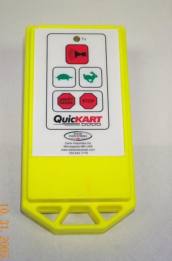
Click to zoom
Application Details
- Equipment Class
- DSC - Part 15 Security/Remote Control Transmitter
- Date of Grant
- Nov 17, 2005
- Application Purpose
- Original Equipment
- Date of Application
- Nov 17, 2005
- Equipment Note
- Periodic Transmitter for Electric Cart Pusher
- Frequency Range
- 433.80000000 - 434.00000000
- Company
- Dane Technologies, Inc.
- Country
- United States
Documents & Files
Document Text
Text extracted from the exhibit documents filed with the FCC. Open a document above to read the original.
Users Manual
DANE TECHNOLOGIES, INC. QUICKART 2000 OWNER’S MANUAL 7105 Northland Terrace, Minneapolis, MN 55428 / 888-544-7779 / 763-544-7779 / Fax 763-544-4234 www.danetechnologies.com 970-005 rev 10-10-05 QUICKART 2000 O WNER’S MANUAL O PERATING INSTRUCTIONS T RAINING GUIDE T ABLE OF CONTENTS T OPIC SECTION Owner’s Manual and Operating Instructions ..................................1 Troubleshooting Flowchart ............................................................2 Training Manual..............................................................................3 Certified Operator’s Test.................................................................4 Note on radio equipment used: This device complies with part 15 of the FCC Rules. Operation is subject to the following two conditions: (1) This device may not cause harmful interference, and (2) This device must accept any interference received, including interference that may cause undesired operation. Changes not expressly approved by Dane Technologies could void the user's authority to operate the equipment. Note: This equipment has been tested and found to comply with the limits for a Class B digital device, pursuant to part 15 of the FCC Rules. These limits are designed to provide reasonable protection against harmful interference in a residential installation. This equipment generates, uses, and can radiate radio frequency energy and, if not installed and used in accordance with the instructions, may cause harmful interference to radio communications. However, there is no guarantee that interference will not occur in a particular installation. If this equipment does cause harmful interference to radio or television reception, which can be determined by turning the equipment off and on, the user is encouraged to try to correct the interference by one or more of the following measures: − Reorient or relocate the receiving antenna. − Increase the separation between the equipment and receiver. − Connect the equipment into an outlet on a circuit different from that which the receiver is connected. − Consult the dealer or an experienced radio/TV technician for help. The abbreviation IC, before the Canadian Registration Number signifies that registration was performed based on a Declaration of Conformity indicating that Industry Canada technical specifications were met. It does not imply that Industry Canada approved the equipment. The CE mark, if present, declares that this equipment meets relevant EU Directives and Standards. DANE TECHNOLOGIES, INC. QUICKART 2000 SERIES OWNER’S MANUAL 28 7105 Northland Terrace, Minneapolis, MN 55428 / 888-544-7779 / 763-544-7779 / Fax 763-544-4234 www.danetechnologies.com 970-005 rev 10-10-05 PROGRAMMING THE REMOTE CONTROL Each hand-held remote control transmitter operates on a unique pre-programmed code. For the QuicKART to operate in the Remote Mode, the receiver, which is in the beacon tower, must be programmed to match the hand held remote control. Every time the batteries in the remote control are replaced, the remote control needs to be reprogrammed to match the receiver code in the beacon tower. If the QuicKART stops responding to the remote control, check the status of the remote battery by depressing one of the remote buttons. If the red LED light does not illuminate, change the battery and reprogram the remote control as follows: 1) Turn on the QuicKART. 2) Switch to "RADIO" on the control panel. 3) Hold remote about arms length from the beacon post. 4) Simultaneously push these three buttons: • Rubber button located on the underside of the square box on the beacon post (see pages 15 and 16); • Brake button on the hand-held remote (page 22); • Horn button on the hand-held remote (page 22). 5) The horn should sound indicating the reprogram is complete and the QuicKART is ready for operation. 6) If the horn did not sound, retry the above steps making sure that the switch on the control panel is on "RADIO". If the horn still did not sound, you can also determine if the reprogram was successful by pressing the slow button on the remote to see if the QuicKART now responds to the remote signal.
Block Diagram
Authorized Agent: Radiometrics Midwest Corporation (815) 293-0772 – [email protected] Block Diagram Authorized Agent: Radiometrics Midwest Corporation (815) 293-0772 – [email protected]
Cover Letter(s)
7105 Northland Terrace Brooklyn Park, MN 55428 Phone:763-544-7779 Fax:763-582-0442 10/24/05 Federal Communications Commission Authorization and Evaluation Division 7435 Oakland Mills Rd. Columbia, MD 21046 Fax 301-344-2050 REFERENCE FCC ID: N2N600-044 Organization: Dane Technologies Request under 47 C.F.R. 0.459 that materials submitted to the commission be withheld from public inspection. Dane Technologies hereby requests that the materials attached here to be withheld from public inspection in accordance with 47 C.F.R. 0.457 & 0.459. Specifically, Dane Technologies requests that the following materials be withheld from public inspection under 47 C.F.R. 0.459 because the Radio Transmitter and Receiver PCB Design documents are considered confidential trade secrets and technical data which customarily would be guarded from competitors: Schematic of Transmitter and Receiver PCB PCB Assembly Bill Of Materials for Transmitter and Receiver (1) Detailed Circuit Schematics of EUT are found in the FCC electronic attachments. Therefore, in accordance with 47 C.F.R. 0.457 & 0.459, Dane Technologies requests that the above listed materials, copies of which are here to be withheld from public inspection. Authorized Signature: _ Daniel Contreras Mechanical Designer Dane Technologies
External Photos
Authorized Agent: Radiometrics Midwest Corporation (815) 293-0772 – [email protected] External EUT Photographs Photograph of Transmitter - Front Photograph of Transmitter - Rear
ID Label/Location Info
Authorized Agent: Radiometrics Midwest Corporation (815) 293-0772 – [email protected] ID Label/Location Drawing of label Location of label on EUT: Note: The picture shows the location of the label on the EUT. The letters are incorrect. See above drawing for the final lettering.
Internal Photos
Authorized Agent: Radiometrics Midwest Corporation (815) 293-0772 – [email protected] Internal EUT Photographs Photograph of Transmitter – Rear Cover Removed Photograph of Transmitter – Inside Front Cover Photograph of Transmitter Board – Foil Side Authorized Agent: Radiometrics Midwest Corporation (815) 293-0772 – [email protected] Photograph of Transmitter Board – Component Side Authorized Agent: Radiometrics Midwest Corporation (815) 293-0772 – [email protected] Photograph of Receiver – Antenna Installed Photograph of Receiver Board – Component Side Photograph of Receiver Board – Foil Side
Operational Description
Radiometrics Midwest Corporation (815) 293-0772 – [email protected] Operational Description The EUT is a handeld 433.9 MHz transmitter. The transmitter is used to control a motorized device for pushing or pulling wheeled loads. Example: shopping carts. The reciever is installed in this device. Up to 6 commands can be sent from the transmitter to the receiver controlling the device. They are: Stop, Forward Slow, Forward Fast, Reverse Slow, Reverse Fast, and Accessory (Horn). These are activated only when the respective push button is held down. If no button is held down the device reverts to stop. The antenna is permanently installed as a trace on the RF circuit board. It is not readily accessible to the end user. Details for compliance a. The intentional radiator is manually operated via switches and under software control, will only begin transmission after a switch is pressed, and will deactivate the transmitter within 500 milliseconds of switch release. b. The intentional radiator is of the “remote switch” category transmitting only a control signal. c. There is no continuous transmission of voice, video, or data. d. A recognition code is transmitted. e. The intentional radiator is manually operated via switches and under software control, will only begin transmission after a switch is pressed, and will deactivate the transmitter within 500 milliseconds of switch release. f. The transmitter is NOT activated automatically. g. No “polling” or “supervision transmissions” are performed. h. The transmitter is NOT employed during emergencies.
Test Report
Radiometrics Midwest Corporation (815) 293-0772 – www.radiomet.com Page 1 of 1 Electromagnetic Compatibility Test Report Tests Performed on a Dane Industries, Inc. Transmitter and Reciever, Model QuicKart SE3/HD3 Radiometrics Document RP-5678 Product Detail: FCC ID: N2N600-044 Equipment type: 433.9 MHz Momentarily Operated Transmitter and Receiver Test Standards: US CFR Title 47, Chapter I, FCC Part 15 Subpart C FCC Part 15 CFR Title 47: 2004 Industry Canada RSS-210, Issue 5 as required for Category I Equipment This report concerns: Original Grant for Certification FCC Part 15.231 RSS-210 section 6.1 Tests Performed For: Test Facility: Dane Industries 7105 Northland Terrace Brooklyn Park, MN 55428 Radiometrics Midwest Corporation 12 East Devonwood Romeoville, IL 60446 Phone: (815) 293-0772 e-mail: [email protected] Test Date(s): (Month-Day-Year) October 13 to November 3, 2005 Document RP-5678 Revisions: Rev. Issue Date Affected Pages Revised By 0 November 7, 2005 1 November 17, 2005 Joseph Strzelecki RADIOMETRICS MIDWEST CORPORATION - EMC Test Report Testing of the Dane Industries, Inc., QuicKart SE3/HD3, Transmitter and Receiver RP-5678 Rev. 1 Page 2 of 2 Table of Contents 1 ADMINISTRATIVE DATA ................................................................................................................... 3 2 TEST SUMMARY AND RESULTS .....................................................................................................3 2.1 RF Exposure Compliance Requirements ..................................................................................... 3 3 EQUIPMENT UNDER TEST (EUT) DETAILS .................................................................................... 4 3.1 EUT Description ........................................................................................................................... 4 3.1.1 FCC Section 15.203 & RSS-210 Section 5.5 Antenna Requirements ................................... 4 3.2 Related Submittals ....................................................................................................................... 4 4 TESTED SYSTEM DETAILS .............................................................................................................. 4 4.1 Tested System Configuration ....................................................................................................... 4 4.2 Special Accessories ..................................................................................................................... 4 5 TEST SPECIFICATIONS AND RELATED DOCUMENTS.................................................................. 4 6 RADIOMETRICS’ TEST FACILITIES .................................................................................................5 7 DEVIATIONS AND EXCLUSIONS FROM THE TEST SPECIFICATIONS......................................... 5 8 CERTIFICATION ................................................................................................................................ 5 9 TEST EQUIPMENT TABLE ................................................................................................................ 5 10 TEST SECTIONS ............................................................................................................................. 6 10.1 Radiated RF Emissions .............................................................................................................. 6 10.1.1 Field Strength Calculation.................................................................................................... 7 10.1.2 Peak to average Correction ................................................................................................. 7 Figure 1. Plot of pulse train ............................................................................................................. 8 10.1.3 Radiated Emissions Test Results (Transmittter).................................................................. 9 10.1.4 Radiated Emissions Test Results (Receiver)..................................................................... 10 Figure 2. Drawing of Radiated Emissions Setup .......................................................................... 11 10.2 Occupied Bandwidth Data ........................................................................................................ 11 Figure 3. Occupied Bandwidth Plot...............................................................................................12 10.3 Transmitter Deactivation Delay ................................................................................................ 14 Notice: This report must not be reproduced (except in full) without the written approval of Radiometrics Midwest Corporation. RADIOMETRICS MIDWEST CORPORATION - EMC Test Report Testing of the Dane Industries, Inc., QuicKart SE3/HD3, Transmitter and Receiver RP-5678 Rev. 1 Page 3 of 3 1 ADMINISTRATIVE DATA Equipment Under Test: A Dane Industries, Transmitter Model 100-224 and Receiver Model 100-223 The system is a QuicKart SE3/HD3 will be referred to as the EUT in this Report Date EUT Received at Radiometrics: (Month-Day-Year) Test Date(s): (Month-Day-Year) October 13, 2005 October 13 to November 3, 2005 Test Report Written By: Test Witnessed By: Joseph Strzelecki Senior EMC Engineer The tests were not witnessed by Dane Industries Radiometrics’ Personnel Responsible for Test: Test Report Approved By Joseph Strzelecki Senior EMC Engineer NARTE EMC-000877-NE Chris W. Carlson Director of Engineering NARTE EMC-000921-NE 2 TEST SUMMARY AND RESULTS The EUT (Equipment Under Test) is a Transmitter and Receiver, QuicKart SE3/HD3, manufactured by Dane Industries. The detailed test results are presented in a separate section. The following is a summary of the test results. Emissions Tests Results Environmental Phenomena Frequency Range Basic Standard Test Result RF Radiated Emissions Transmitter 30-4400 MHz RSS-210 & FCC Part 15 Pass RF Radiated Emissions Receiv…
Text truncated - open the document above for the full version.
Test Setup Photos
Authorized Agent: Radiometrics Midwest Corporation (815) 293-0772 – [email protected] Test Setup Photographs Photograph of Radiated Emissions Test Setup Authorized Agent: Radiometrics Midwest Corporation (815) 293-0772 – [email protected]
Contact Information
Applicant
Daniel Contreras(Mechanical Designer)
Test Firm
Radiometrics Midwest Corp.Joseph Strzelecki
Technical Specifications
| # | Rule Parts | Frequency Range | Power Output |
|---|---|---|---|
| 1 | 15.231 | 433.8 MHz - 434 MHz | - |
Other Applications from Dane Technologies, Inc.

N2N600-041
Aug 24, 2003Remote Control for Electric Utility Machine
Equipment Class
DSC - Part 15 Security/Remote Control Transmitter