N3F-ATTI201Transceiver Module
Advanced Tracking Technology Inc.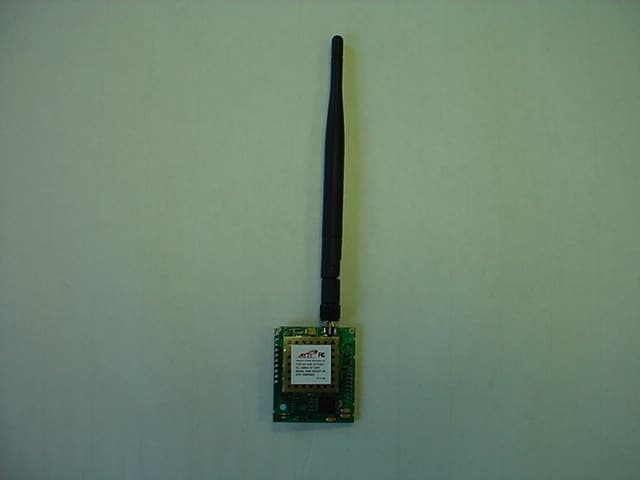
Click to zoom
Application Details
- Equipment Class
- DSS - Part 15 Spread Spectrum Transmitter
- Date of Grant
- Jul 13, 2006
- Application Purpose
- Original Equipment
- Date of Application
- Jul 13, 2006
- Equipment Note
- Transceiver Module
- Frequency Range
- 902.70000000 - 927.20000000
- Country
- United States
Documents & Files
Document Text
Text extracted from the exhibit documents filed with the FCC. Open a document above to read the original.
Users Manual
ATTI 900 mhz Transceiver Users Manual Description The ATTI 900 mhz Transceiver module is a frequency hopping spread spectrum transceiver capable of 2 way transportation of message packets in the 900 MHz ISM band. A standard serial interface operating at 3-volt CMOS levels is used to communicate with the host device. FCC Compliance Compliance Statement (Part 15.19) This device complies with Part 15 of the FCC Rules and with RSS-210 of Industry Canada. Operation is subject to the following two conditions: 1. This device may not cause harmful interference, and 2. This device must accept any interference received, including interference that may cause undesired operation. Warning (Part 15.21) Changes or modifications not expressly approved by the party responsible for compliance could void the user’s authority to operate the equipment. RF Exposure (OET Bulletin 65) To comply with FCC’s RF exposure limits for general population / uncontrolled exposure, the antenna(s) used for this transmitter must be installed to provide a separation distance of at least 20 cm from all persons and must not be collocated or operating in conjunction with any other antenna or transmitter. FCC ID: N3F-ATTI201 Canada ID: 4385A-ATTI201 S/N: ???????? MODEL: ASM-000201-04. Made in USA OEM Responsibility to the FCC Rules and Regulations The “ATTI 900 mhz Transceiver” Module has been certified per FCC Part 15 rules for integration into products without further testing or certification. To fulfill the FCC certification requirements the OEM of the “ATTI 900 mhz Transceiver” Module must ensure that the information provided on the “ATTI 900 mhz Transceiver” Label is placed on the outside of the final product. The “ATTI 900 mhz Transceiver” Module is labeled with its own FCC ID Number. If the FCC ID is not visible when the module is installed inside another device, then the outside of the device into which the module is installed must also display a label referring to the enclosed module. This exterior label can use wording such as the following: “Contains Transmitter Module FCC ID: N3F-ATTI201 Contains FCC ID: N3F-ATTI201 The OEM of the “ATTI 900 mhz Transceiver” Module must only use the approved antenna, which has been certified with this module. The OEM of the “ATTI 900 mhz Transceiver” Module must test their final product configuration to comply with Unintentional Radiator Limits before declaring FCC compliance per Part 15 of the FCC rules. Industry Canada Statement per Section 4.0 of RSP-100 The term "IC:" before the certification / registration number only signifies that the Industry Canada technical specifications were met. Section 7.1.5 of RSS-GEN Operation is subject to the following two conditions: 1) this device may not cause harmful interference, and 2) this device must accept any interference received, including interference that may cause undesired operation. _______________________________________________________________ Section 7.1.4 of RSS-GEN This device has been designed to operate with an antenna having a maximum gain of [60] dB. Antenna having a higher gain is strictly prohibited per regulations of Industry Canada. The required antenna impedance is [ 50] ohms." Section 7.1.5 of RSS-GEN To reduce potential radio interference to other users, the antenna type and its gain should be so chosen that the equivalent isotropically radiated power (EIRP) is not more than that required for successful communication. _______________________________________________________________ Section 2.6 of RSS-102 This portable transmitter with its antenna complies with Industry Canada RF Exposure Limits for General Population / Uncontrolled Exposure. Antenna Specifications Compliance with FCC regulations may only be maintained using the specified antennas. This module is designed for use with ATTI part #G-39223, modified monopole antenna. Use of any other antenna is a violation of FCC rules. The antenna connection uses a reverse polarity SMA connector that is supplied to prevent the use of other types of antennas. Electrical/Connection Specifications The module should be operated within the electrical limits provided in the section. Operation outside of the parameters may damage the unit. Power is supplied by the host device through the interface connector and must be in accordance with the following operating voltage and current requirements. Parameter Min Typ Max Units Operating Voltage 2.70 3.00 3.60 VDC Transmit Current 750 1300 mA Receive Current 20 mA Sleep Current 5 10 μA Operating Temperature -40 +85 °C Connector Pin Out Pin # Name Description 1 gnd Ground 2 VCC Power Input 3 XCVR RX Receive Data In 4 XCVR TX Transmit Data Out 5 XCVR CTS CTS input 6 XCVR RST Reset In 7 TCK Jtag Signal 1 8 TMS Jtag Signal 2 9 TPI Jtag Signal 3 10 TDO/TPI Jtag Signal 4 The transmit power of the module is one watt. In some installations there may be traces connected to the communication pins of the module that are long enough to act as antennas at 900 MHz. There is the possibility of inducing enough voltage to false trigger a CMOS input. To avoid this situation it may be necessary to install a 22 pF, 0603 size capacitor from each of the 3 signal lines to ground. The capacitors should be located as close as possible to the connector in the host board. Good RF layout techniques should be observed. Mounting Location A vertical orientation is required. Mounting is accomplished via the 10 pin 0.1” header along the edge of the board. It is necessary to mount the module in such a way that user is never closer than 20 cm to the antenna. Additionally, the transceiver may not be co- located with any other antenna or transmitter. NOTE: This equipment has been tested and found to comply with the limits for a Class B digital device, pursuant to Part 15 of the FCC Rules. These limits are designed to provide reasonable protection against harmful interference in a residential installation. This equipment generates, uses and can radiated radio frequency en…
Text truncated - open the document above for the full version.
Cover Letter(s)
File:Modular Cover Letter v1 2 CONFIDENTIAL Page 1 of 1 July 13, 2006 Re: Modular Transmitter Approval for ATTI Module FCC ID: N3F-ATTI201 Gentlemen, The following information is being provided per the requirements of DA00-1407 regarding modular approval of Part 15 devices. This transceiver is a complete RF module with an integral reference oscillator. External connections are provided for power, data communication, and antenna. The following numbered items correspond to similarly numbered paragraphs in DA00-1407. Each item is a response to the requirements of that document. 1) The module has integral RF shielding to isolate it from surrounding equipment and the larger environment in general. 2) All inputs are processed as data by the on-board microcontroller. The outside user has no direct control of transmit modulation. 3) There is not a hardware voltage regulator on board. Instead, the microcontroller monitors power supply voltage on a continuous basis. Should the supply voltage be found to be greater than the specified maximum of 3.5 volts the unit will refuse to transmit. 4) A reverse gender SMA style connector is employed to prevent the use of antennas other than the type specified. This is in accordance with Part 15.203. 5) The module was tested in a stand-alone configuration and found to be compliant with Part 15 regulations. 6) An FCC ID label is affixed to each unit at the time of manufacture. Information is also clearly presented in the user guide about labeling requirements for the final assembly. 7) This unit is compliant with Part 15.247. Installation and other requirements are presented in the user guide to allow the unit to be correctly installed. 8) 8The unit is compliant with the RF exposure requirements of Parts 15.247, 15.1091, and 15.1093. Further information may be obtained from LS Research, LLC. Sincerely, John Lofgren
Cover Letter(s)
"Teresa White" <[email protected]> 07/06/2006 05:06 PM To Yunus Faziloglu/USA/VERITAS@VERITAS cc "Aidi" <[email protected]>, "Abtin Spantman" <[email protected]> bcc Subject RE: CS01941 Advanced Tracking Technologies FCC ID:N3F-ATTI201 TCB Questions Hi Yunus, Please see below (and attached revised test report) for responses to balance of issues. Enjoy your evening. Regards, Teresa LS Research, LLC W66 N220 Commerce Court Cedarburg, WI 53012 « Direct: 262.421.4991 « Main: 262.375.4400 ¬ Fax: 262.364.2649 | Email: twhite @lsr.com Visit us on the web: www.lsr.com Notice: This message and any included attachments are intended only for the use of the addressee, and may contain information that is privileged or confidential. If you are not the intended recipient, you are hereby notified that any review, copying or distribution of this communication is strictly prohibited. If you have received this e-mail in error, please destroy the original message and any copies or printouts hereof. Any views or opinions presented are solely those of the author of this e-mail, and do not necessarily represent those of LS Research, LLC, unless otherwise specifically stated. From: [email protected] [mailto:[email protected]] Sent: Wednesday, May 31, 2006 3:21 PM To: Teresa White Subject: CS01941 Advanced Tracking Technologies FCC ID:N3F-ATTI201 TCB Questions Hi Teresa, Please address the following issues for this application, 1. Operational description must specify the modulation type used by the module. Response: The type of modulation used is FSK. 2. The following issues are related to the manual, Response: Previously submitted to Curtis-Straus. i) "OEM responsibilities" section (Pg 2 - line 5) shows the FCC ID by itself after "or" statement. The word "Contains" must be inserted before "FCC ID" to avoid any confusion. ii) Pg 2 "Antenna Specifications" section mentions a 1/4 wave monopole antenna, while operational description mentions 1/2 wave dipole antenna. Please clarify/correct. iii) 15.105(b) statement is required in the manual. 3. "Modular Approval Request" letter mentions reverse gender SMA style connector for justification of unique antenna connector. However the connector seen in the external photos looks like a standard SMA. Please clarify how the module meets 15.203 requirement. Response: (i) new photos of correct EUT were previously submitted to Curtis-Straus. (ii) Verbiage added to product description of test report (page 6). 4. Radiated emissions readings on Pg11 of the report data table for frequencies between 874-944 MHz excluding the 902-928 fundamental band are considerably high. The plot on Pg 16 of the report showing the frequency span of 300-902 MHz is much lower. Please clarify this difference. Response: The captures/plots used in the test report were of the wrong channel. Test report revised. 5. Please provide the peak readings at 1805.4, 1830.6 and 1854.4 MHz frequencies on Pg 12 data table? Please also specify the receiver system settings used for peak measurements (RBW, VBW) at those frequencies? Response: Plots of 2 nd harmonics that show average det. Value and peak det. Value have been added to the test report. Clerical error, more than one board revision was used. Included data from earlier revision in the test report by mistake. Peak Measurements were done using RBW=1 MHz/VBW=1 MHz. Average Measurements were done using RBW = 1 MHz/ VBW=10 Hz. 6. On section 13 of the report (conducted spurious emissions) the levels of 2nd harmonics are unusually high. Please measure the fundamental emissions with 100kHz RBW and 100kHz VBW for better comparison to the harmonics. Reduced BW at the fundamental may not provide the required 20dB clearance for channel 52 and others. Response: Clerical error. Wrong data included in test report. Measurements were re-taken. 7. Please note that on section 15 of the report, 10 sec criteria applies instead of 20 sec, as the 20dB BW is wider than 250kHz. Response: Re-tested for 10s occupancy and results included in test report. 8. Section 16 of the report (voltage variation) states that EUT is programmed to stop the transmission if input voltage exceeds 3.5VDC. However "Modular Approval Request" letter claims 3.6 VDC and it states that unit stopped transmission at 3.63VDC. Please clarify this difference. Has it been verified by test that the unit stopped transmitting below 2.8V and above 3.5V? Response: (i) Previously responded (ii) Added verbiage in the test report (iii) Power cut off software tested and verified. Note: In responding to issues 4 through 6, the EUT was re-tested in the 3 Meter Chamber for the frequency range 300 MHz – 5000 MHz; Harmonics up to the 5 th were tested and documented for all 3 channels. Fundamental power levels were also tested for and documented for all 3 channels. Best Regards, Yunus Faziloglu Curtis-Straus / Bureau Veritas
External Photos
Advanced Tracking Technologies, Inc. (ATTI) ATTI XETI MODULE FCC ID#: N3F-ATTI201 Photo One – External RF Board, Shielded Advanced Tracking Technologies, Inc. (ATTI) ATTI XETI MODULE FCC ID#: N3F-ATTI201 Photo Two – External Close Up of RF Section, Shielded Advanced Tracking Technologies, Inc. (ATTI) ATTI XETI MODULE FCC ID#: N3F-ATTI201 Photo Three – External Close Up of FCC ID Label Advanced Tracking Technologies, Inc. (ATTI) ATTI XETI MODULE FCC ID#: N3F-ATTI201 Photo Four – External Antenna Connected Advanced Tracking Technologies, Inc. (ATTI) ATTI XETI MODULE FCC ID#: N3F-ATTI201 Photo Five – External RF Section with Antenna Connected Advanced Tracking Technologies, Inc. (ATTI) ATTI XETI MODULE FCC ID#: N3F-ATTI201 Photo Six – External Back Side of RF Board, With Antenna Connector Advanced Tracking Technologies, Inc. (ATTI) ATTI XETI MODULE FCC ID#: N3F-ATTI201 Photo Seven – External Close Up of Antenna Connector
ID Label/Location Info
TDS No. B-423 Effective Date: 06/03/2004 BRADY WORLDWIDE, INC. P.O. Box 2131 Milwaukee, WI 53201-2131 Tel. 414/358-6600 Fax 800/292-2289 BRADYBONDZ(TM) B-423 THERMAL TRANSFER PRINTABLE GLOSSY WHITE POLYESTER LABEL STOCK Description: GENERAL Print Technology: Thermal transfer Materials Type: White polyester Finish: Glossy white Adhesive: Permanent acrylic APPLICATIONS Electronic PCB and component identification, bar code label and rating plates. RECOMMENDED RIBBONS Brady series R6000 Brady series R4400 (colors - red, blue, green, white) Brady series R4900 and R6200 (alternates) AGENCY APPROVALS UL: B-423 is a UL Recognized Component to UL969 Labeling and Marking Standard when printed with Brady Series R6000 ribbon. See UL file MH17154 for specific details. UL information can be accessed on line at UL.com. Search in Certifications area. The Brady Series R4900 ribbon is also UL approved. CSA: B-423 is CSA Accepted to C22.2 No.0.15-95 Adhesive Labels Standard when printed with Brady Series R6000 ribbon. See CSA file 041833 for specific details. CSA information can be accessed online at directories.csa- international.org. DIN VDE 0472 Part 815: Brady B-423 meets requirements of a halogen-free material per DIN VDE 0472 part 815. (Statement based on review of product construction and confirmation halogen content test run at an independent test laboratory.) Details: PHYSICAL PROPERTIES TEST METHODS AVERAGE RESULTS Thickness ASTM D 1000 -Substrate -Adhesive -Total 0.002 inch (0.0508 mm) 0.001 inch (0.0254 mm) 0.003 inch (0.0762 mm) Adhesion to: -Stainless Steel - Painted Enamel - Textured ABS ASTM D 1000 20 minute dwell 24 hour dwell 20 minutes dwell 24 hour dwell 20 minutes dwell 24 hour dwell 51 oz/inch (56 N/100 mm) 78 oz/inch (85 N/100 mm) 54 oz/inch (59 N/100 mm) 67 oz/inch (73 N/100 mm) 10 oz/inch (11 N/100 mm) 15 oz/inch (17 N/100mm) Tack ASTM D 2979 Polyken™ Probe Tack 1 second dwell 21 oz (600 g) Dielectric Strength ASTM D 1000 8600 Volts B-423 is not recommended for low surface energy surfaces such as polyethylene and polypropylene. Performance properties tested on B-423 printed with Series R6000 and R6200 ribbons using the Bradyprinter™ THT Model 300X-Plus thermal transfer printer. Printed samples were laminated to aluminum and allowed to dwell 24 hours before exposure to the indicated environments. Unless noted, results are the same for both ribbons. PERFORMANCE PROPERTIES TEST METHOD TYPICAL RESULTS High Service Temperature 30 days at various temperatures No visible effect to label at 110°C. Slight discoloration at 120°C; moderate discoloration at 145°C but label is still functional. Low Service Temperature 30 days at -70°C No visible effect Short Term High Service Temperature 5 minutes at various temperatures No visible effect to label at 180°C. Slight discoloration and label shrinkage at 200°C; label is functional. Label becomes nonfunctional at 210°C due to label shrinkage. Humidity Resistance 30 days at 100°F (37°C) and 95% relative humidity. No visible effect UV Light Resistance 30 days in UV Sunlighter™ 100 Slight discoloration Weatherability ASTM G26 30 days in Xenon Arc Weatherometer No visible effect Salt Fog Resistance ASTM B 117 30 days in 5% salt fog solution chamber No visible effect PERFORMANCE PROPERTY CHEMICAL RESISTANCE Samples were printed with Series R6000 and R6200 ribbons using a Bradyprinter™ 300X-Plus thermal transfer printer. Samples were laminated to aluminum panels and allowed to dwell 24 hours prior to testing. Testing was conducted at room temperature and consisted of 30 minute immersions in the specified test fluid. After immersion, the samples were removed from the test fluid and the printed image rubbed 10 times with a cotton swab saturated with the test fluid. The rating scale below shows the effect to the quality of the print for each sample. SUBJECTIVE OBSERVATION OF VISUAL CHANGE EFFECTS TO PRINTED IMAGE R6000 R6200 CHEMICAL REAGENT EFFECT TO LABEL STOCK WITHOUT RUB WITH RUBWITHOUT RUB WITH RUB Acetone Slight adhesive ooze 1 5 1 5 Toluene Slight adhesive ooze 1 5 1 5 Isopropyl Alcohol No visible effect 1 1 1 1 Mineral No visible 1 1 1 1 Spirits effect Gasoline Slight adhesive ooze 1 1 1 1 JP-8 Jet Fuel Slight adhesive ooze 1 1 1 1 Brake Fluid No visible effect 1 1-2 1 5 Skydrol® 500B-4 Slight adhesive ooze 1 5 2 5 SAE 20 WT Oil at 70°C No visible effect 1 1 1 1 MIL 5606 Oil No visible effect 1 1 1 1 Formula 409® Cleaner No visible effect 1 1 1 1 Northwoods™ Buzz Saw Citrus Degreaser No visible effect 1 1 1 1 Deionized Water No visible effect 1 1 1 1 Rating Scale: 1= no visible effect 2= slight smear or print removal, detectable but minimal smear 3= moderate smear or print removal (print still legible) 4= severe smear or print removal (print illegible or just barely legible) 5= complete print and/or topcoat removal NP= print removed prior to rub Product testing, customer feedback, and history of similar products, support a customer performance expectation of at least two years from the date of receipt for this product as long as this product is stored in its original packaging in an environment below 80 degrees F and 60% RH . We are confident that our product will perform well beyond this time frame. However, it remains the responsibility of the user to assess the risk of using such product. We encourage customers to develop functional testing protocols that will qualify a product's fitness for use, in their actual applications. Trademarks and References: BradyBondz™ is a trademark of Brady Worldwide, Inc. BradyPrinter™ is a trademark of Brady Worldwide, Inc. Formula 409® is a registered trademark of the Clorox Company Northwoods™ is a trademark of the Superior Chemical Corporation Polyken™ is a trademark of Testing Machines Inc. Skydrol® is a registered trademark of the Monsanto Company Sunlighter™ is a trademark of the Test Lab Apparatus Company ASTM: American Society for Testing and Materials (U.S.A.) CSA: Canadian Standards Association SAE: Socie…
Text truncated - open the document above for the full version.
Internal Photos
ADVANCED TRACKING TECHNOLOGIES, INC., ATTI XETI Module FCC ID#: N3F-ATTI201 Photo One – Internal RF Section – Shield Removed
Parts List/Tune Up Info
NEARSON Ω Alternative Connectors .SMA Reverse Polarity Plug(female).SMA Reverse Thread Plug(male) http://www.nearson.com
RF Exposure Info
Prediction of MPE limit at a given distance Equation from page 18 of OET Bulletin 65, Edition 97-01 where:S = power density P = power input to the antenna G = power gain of the antenna in the direction of interest relative to an isotropic radiator R = distance to the center of radiation of the antenna Maximum peak output power at the antenna terminal:28.60(dBm) Maximum peak output power at the antenna terminal:724.4359601(mW) Antenna gain(typical):2(dBi) Maximum antenna gain:1.584893192(numeric) Prediction distance:20(cm) Prediction frequency:915(MHz) MPE limit for uncontrolled exposure at prediction frequency:0.6(mW/cm^2) Power densit y at prediction frequency:0.228418(mW/cm^2) 2 4R PG S π =
Test Report
LS Research, LLC W66 N220 Commerce Court Cedarburg, WI 53012 262-375-4400 Fax: 262-375-4248 COMPLIANCE TESTING OF : ATTI MODULE Model: ASM-000201-04 Prepared For: Advanced Tracking Technologies, Inc. Attn.: Mr. Bob Rooney 6001 Savoy Drive Suite 600 Houston, TX 77036 Test Report Number: 306206 –TX-TCB Rev. 2 Test Dates: April 3 rd – May 18 th 2006 All results of this report relate only to the items that were tested. This report is not to be reproduced, except in full, without written approval of LS Research, LLC. LS Research, LLC Page 2 of 55 Test Report Number: 306206-TX-TCB Rev. 2 Prepared For: Advanced Tracking Technologies, Inc. Table of Contents Section Description Page Index 2 1 LS Research, LLC in Review 3 2 Signature Page 4 3 Product and General Information 5 4 Introduction 5 5 Product Description 6 6 Test Requirements 7 7 Summary of Test Report 7 8 Radiated Emissions Test 8-21 9 Band-Edge Measurements 22-23 10 Conducted RF Emissions onto AC Power Line 24-28 11 Occupied Bandwidth 29-30 12 Power Output 15.247 (b)(2) 31-33 13 Spurious Emissions 15.247(d) 34-37 14 Minimum Channel Separation 38-44 15 Channel Occupancy 45-48 16 Frequency and Power Stability Requirements 49-50 17 Equal Channel Usage 51 18 Pseudorandom Hopping Pattern 51 19 Receiver Synchronization 52 20 Receiver Input Bandwidth 52 21 MPE Calculations 53 Appendix A Test Equipment List 54 B Antenna Specification Sheets 55 LS Research, LLC Page 3 of 55 Test Report Number: 306206-TX-TCB Rev. 2 Prepared For: Advanced Tracking Technologies, Inc. 1. LS Research, LLC In Review LS Research, LLC - Accreditations and Listing’s As an EMC Testing Laboratory, our Accreditation and Assessments are recognized through the following: A2LA – American Association for Laboratory Accreditation Accreditation based on ISO/IEC 17025 : 1999 with Electrical (EMC) Scope of Accreditation A2LA Certificate Number: 1255.01 Federal Communications Commission (FCC) – USA Listing of 3 Meter Semi-Anechoic Chamber based on Title 47 CFR – Part 2.948 FCC Registration Number: 90756 Industry Canada On file, 3 Meter Semi-Anechoic Chamber based on RSS-212 – Issue 1 File Number: IC 3088-A On file, 3 and 10 Meter OATS based on RSS-212 – Issue 1 File Number: IC 3088 U. S. Conformity Assessment Body (CAB) Validation Validated by the European Commission as a U. S. Competent Body operating under the U. S. /EU, Mutual Recognition Agreement (MRA) operating under the European Union Electromagnetic Compatibility –Council Directive 2004/108/EC (formerly 89/336/EEC, Article 10.2) Date of Validation: January 16, 2001 Validated by the European Commission as a U.S. Notified Body operating under the U.S./EU, Mutual Recognition Agreement (MRA) operating under the European Union Telecommunication Equipment – Council Directive 99/5/EC, Annex V. Date of Validation: November 20, 2002 Notified Body Identification Number: 1243 LS Research, LLC Page 4 of 55 Test Report Number: 306206-TX-TCB Rev. 2 Prepared For: Advanced Tracking Technologies, Inc. 2. Signature Page Prepared By: July 6, 2006 Teresa A. White, Document Coordinator Date Tested By: July 6, 2006 Abtin Spantman, EMC Engineer Date Tested By: July 6, 2006 Khairul A. Zainal, EMC Engineer Date Approved By: July 6, 2006 Brian E. Petted, VP of Engineering Date LS Research, LLC Page 5 of 55 Test Report Number: 306206-TX-TCB Rev. 2 Prepared For: Advanced Tracking Technologies, Inc. 3. Product and General Information Manufacturer: Advanced Tracking Technologies, Inc. Date(s) of Test: April 3 rd – May 18 th , 2006 Test Engineer(s): √ Khairul A. Zainal Abtin Spantman Ken Boston Model #: ASM-000201-04 Serial #: 05450375 Voltage: 3.3 VDC Operation Mode: Continuous transmit and ‘Hopping’ mode 4. Introduction Between April 3 rd and May 18 th , 2006, a series of Conducted and Radiated RF Emission tests were performed on one sample of the Advanced Tracking Technologies, Inc., transceiver Module, Model Number ASM-000201-04, Serial Number 05450375, here forth referred to as the “Equipment Under Test” or “EUT”. These tests were performed using the procedures outlined in ANSI C63.4- 2003 for intentional radiators, and in accordance with the limits set forth in FCC Part 15.247 (Industry Canada RSS-210, Annex 8, Section 8.1) for a low power transmitter. These tests were performed by Khairul A. Zainal, EMC Engineer of LS Research, LLC. All Radiated and Conducted RF Emission tests were performed upon the EUT to measure the emissions in the frequency bands described in FCC Title 47 CFR Part 15, including 15.35, 15.209, 15.247 and Industry Canada RSS-210, Annex 8, Section 8.1 for a Frequency Hopping Spread Spectrum Transmitter to determine whether these emissions are below the limits expressed within the standards. These tests were performed in accordance with the procedures described in the American National Standard for methods of measurement of Radio-Noise Emissions from Low- Voltage Electrical and Electronic Equipment in the Range of 9 kHz to 40 GHz (ANSI C63.4-2003). Another document used as a reference for the EMI Receiver specification was the Comite International Special Des Perturbations Radioelelectriques (CISPR) Number 16-1, 2003. All tests were performed at LS Research, LLC in Cedarburg, Wisconsin, unless otherwise noted. LS Research, LLC Page 6 of 55 Test Report Number: 306206-TX-TCB Rev. 2 Prepared For: Advanced Tracking Technologies, Inc. 5. Product Description The Advanced Tracking Technologies, transceiver Module is a data module designed to operate as a frequency hopper on 52 channels with FSK type modulation in the 902 MHz – 928 MHz ISM band, with a nominal RF output power of 1 Watt. The module operates on 3.3 VDC, 800mA, and transfers data at 76.810 kbps. During the testing, the EUT was programmed to operate in the desired modes using proprietary software and a laptop PC through an RS-232 link, using a programming fixture board, while being supplied with a 3.3 VDC by means of an external power supply. Supply voltage into the module i…
Text truncated - open the document above for the full version.
Test Setup Photos
Advanced Tracking Technologies, Inc. (ATTI) Test Setup Photos FCC ID: N3F-ATTI201 IC: 4385A-ATTI201 Page 1 of 3 Photos Taken During Radiated Emission Testing View of the EUT setup in vertical orientation View of the EUT setup in Horizontal orientation Advanced Tracking Technologies, Inc. (ATTI) Test Setup Photos FCC ID: N3F-ATTI201 IC: 4385A-ATTI201 Page 2 of 3 View of the EUT setup in Side orientation Advanced Tracking Technologies, Inc. (ATTI) Test Setup Photos FCC ID: N3F-ATTI201 IC: 4385A-ATTI201 Page 3 of 3 Photo(s) Taken During Conducted Emission Testing Setup for the Conducted Emissions Test
Contact Information
Applicant
Paul M. Glass(President)
800-279-0035
Test Firm
LS Research, LLCRyan Urness
Technical Specifications
| # | Rule Parts | Frequency Range | Power Output |
|---|---|---|---|
| 1 | 15C | 902.7 MHz - 927.2 MHz | 724.00 mW |
Other Applications from Advanced Tracking Technology Inc.
N3F-ST869
Aug 05, 2002Data Transceiver
Equipment Class
DSS - Part 15 Spread Spectrum Transmitter