N3S2001B02Remote device identification transmitter
Addison Hi-Tech Incorporated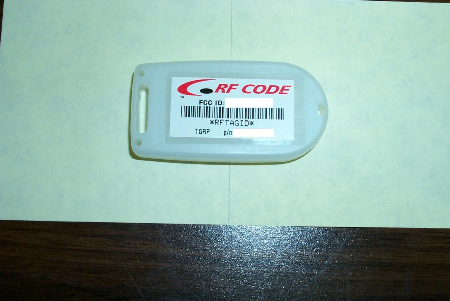
Click to zoom
Application Details
- Equipment Class
- DSC - Part 15 Security/Remote Control Transmitter
- Date of Grant
- Sep 16, 2001
- Application Purpose
- Original Equipment
- Date of Application
- Sep 16, 2001
- Equipment Note
- Remote device identification transmitter
- Frequency Range
- 303.80000000 - 303.80000000
- Company
- Addison Hi-Tech Incorporated
- Country
- United States
Documents & Files
Document Text
Text extracted from the exhibit documents filed with the FCC. Open a document above to read the original.
Users Manual
Spider IIIAR Installation 1250 South Clearview, Mesa, Arizona 85208 (480) 969-2828 Page 1 of 14 Spider IIIAR Reader Installation Instructions FCC Certification NOTE: This equipment has been tested and found to comply with the limits for a Class B digital device, pursuant to part 15 of the FCC rules. These limits are designed to provide reasonable protection against harmful interference in a residential installation. This equipment generates, uses and can radiate radio frequency energy and, if not installed and used in accordance with the instructions, may cause harmful interference to radio communications. However, there is no guarantee that interference will not occur in a particular installation. If this equipment does cause harmful interference to radio or television reception, which can be determined by turning the equipment off and on, the user is encouraged to try to correct the interference by one or more of the following measures: ! Reorient or relocate the receiving antenna. ! Increase the separation between the equipment and receiver. ! Connect the equipment into an outlet on a circuit different from that to which the receiver is connected. ! Consult the dealer or an experienced radio/TV technician for help. Spider IIIAR Installation 1250 South Clearview, Mesa, Arizona 85208 (480) 969-2828 Page 2 of 14 Introd uction When placing the reader in a permanent position, several factors need to be considered that contribute to choosing the reader’s position. ! RF visibility ! Tag density ! Range configuration ! Access to Power ! Access to LAN communication ! Communication bandwidth ! Environmental conditions. ! Serviceability. RF Visibility RF Visibility refers to the reader’s ability to “see” the tags in its reporting area. The best condition is to have an RF line-of-sight between the reader and all tags. In most cases the Spider IIIAR’s RF line-of-sight is equivalent to a visual line-of-sight. However, there are some materials that are transparent to RF but not to light. The spider reader can read tags through a typical wall such as found in an office environment. Some walls are more transparent than others. Metal wall studs, typically grounded to the electrical system ground, absorb the tags signal. However, because there is space between studs, some signal does get through. Different walls have different RF transparencies. Because some walls are more RF transparent than others, they need to be tested to determine their RF transparency. Example: a wall composed of wood studs and gypsum wallboard is more transparent than a wall with steel studs and gypsum wallboard. Metal objects reflect or absorb RF signals; they are not transparent to RF. Example: If a tag is placed next to a metal filing cabinet, the RF signal from the tag is reflected off the filing cabinet’s metal and is seen best from the same side of the cabinet on which the tag is located. The tag can be seen from the other side of the cabinet due to the RF signal multi-pathing (reflecting off of several metal surfaces). A multipath signal is usually weaker than a direct path signal. Spider IIIAR Installation 1250 South Clearview, Mesa, Arizona 85208 (480) 969-2828 Page 3 of 14 Example: if a tag is placed inside a metal filing cabinet, the signal from the tag is reflected off the metal of the interior of the filing cabinet several times and most of the signal is eventually absorbed inside the cabinet. The tag can be seen from outside the cabinet due to multi-pathing of the RF signal that leaks out of the drawer openings of the cabinet. That tag’s signal that leaks out will be considerably weaker than if the signal were seen directly. Earth ground or a grounded metal structure actually absorbs the tag’s signal. If you place the tag or the reader on the ground, there is a very good chance you will not see the tag’s ID because the earth ground absorbs the tag’s signal. Multi-story buildings generally have grounded rebar in the floor structure of each level. The grounded rebar in the floor can be as RF absorbing as earth ground. Since the roof of one room is the floor of the room above, mounting a spider reader on or near the roof may be the same as setting it on the ground; you may not see the tag’s ID because the grounded rebar absorbs the tag’s signal. Different floors have different transparencies to RF. When planning reader placements, because some floors are more RF transparent than others, they need to be tested to determine their RF transparency. To minimize RF interference, maintain a four to six foot separation between the Spider Reader antennas and potential RF radiators such as computers, monitors, printers, wireless network access points and electronic office equipment. The local “radio noise environment” can limit the reader’s effective range. Grounded and reflective metallic structures around the reader’s antennas and/or tags affects the system’s performance. The best location for placing a reader is line of sight to the most number of tags to be being covered by this reader. Spider IIIAR Installation 1250 South Clearview, Mesa, Arizona 85208 (480) 969-2828 Page 4 of 14 Tag Density The Spider IIIAR reader can handle a limited number of tags at the same time. The optimum number of tags varies with the chirp rate of the tag, the distance between the reader and the tags, the antennas on the reader, and the range setting on the reader. For example, the reader can efficiently handle about 500 seven-second tags at a normal distribution at the same time. If the tag chirp rate goes to one second, the same reader can handle about 70 tags at the same time. If the chirp rate goes to 14 seconds, the same reader can handle about 1000 tags at the same time. If there are more tags in the area of a reader than can normally be handled, the range setting of the reader can be reduced to limit the number of visible tags to a manageable quantity. In a highly mobile tag population, transient densities need to be calculated to assure th…
Text truncated - open the document above for the full version.
Users Manual
Spider IIIAR Installation 1250 South Clearview, Mesa, Arizona 85208 (480) 969-2828 Page 1 of 15 Spider IIIAR Reader Installation Instructions FCC Certification This device complies with part 15 of the FCC rules. Operation is subject to the following two conditions: (1) this device may not cause harmful interference, and (2) this device must accept any interference received, including interference that may cause undesired operation. Warning: Changes or modifications not expressly approved by the party responsible for compliance could void the user's authority to operate the equipment. Spider IIIAR Installation 1250 South Clearview, Mesa, Arizona 85208 (480) 969-2828 Page 2 of 15 Introduction When placing the reader in a permanent position, several factors need to be considered that contribute to choosing the reader’s position. ̧ RF visibility ̧ Tag density ̧ Range configuration ̧ Access to Power ̧ Access to LAN communication ̧ Communication bandwidth ̧ Environmental conditions. ̧ Serviceability. RF Visibility RF Visibility refers to the reader’s ability to “see” the tags in its reporting area. The best condition is to have an RF line-of-sight between the reader and all tags. In most cases the Spider IIIAR’s RF line-of-sight is equivalent to a visual line-of-sight. However, there are some materials that are transparent to RF but not to light. The spider reader can read tags through a typical wall such as found in an office environment. Some walls are more transparent than others. Metal wall studs, typically grounded to the electrical system ground, absorb the tags signal. However, because there is space between studs, some signal does get through. Different walls have different RF transparencies. Because some walls are more RF transparent than others, they need to be tested to determine their RF transparency. Example: a wall composed of wood studs and gypsum wallboard is more transparent than a wall with steel studs and gypsum wallboard. Metal objects reflect or absorb RF signals; they are not transparent to RF. Example: If a tag is placed next to a metal filing cabinet, the RF signal from the tag is reflected off the filing cabinet’s metal and is seen best from the same side of the cabinet on which the tag is located. The tag can be seen from the other side of the cabinet due to the RF signal multi-pathing (reflecting off of several metal surfaces). A multipath signal is usually weaker than a direct path signal. Spider IIIAR Installation 1250 South Clearview, Mesa, Arizona 85208 (480) 969-2828 Page 3 of 15 Example: if a tag is placed inside a metal filing cabinet, the signal from the tag is reflected off the metal of the interior of the filing cabinet several times and most of the signal is eventually absorbed inside the cabinet. The tag can be seen from outside the cabinet due to multi-pathing of the RF signal that leaks out of the drawer openings of the cabinet. That tag’s signal that leaks out will be considerably weaker than if the signal were seen directly. Earth ground or a grounded metal structure actually absorbs the tag’s signal. If you place the tag or the reader on the ground, there is a very good chance you will not see the tag’s ID because the earth ground absorbs the tag’s signal. Multi-story buildings generally have grounded rebar in the floor structure of each level. The grounded rebar in the floor can be as RF absorbing as earth ground. Since the roof of one room is the floor of the room above, mounting a spider reader on or near the roof may be the same as setting it on the ground; you may not see the tag’s ID because the grounded rebar absorbs the tag’s signal. Different floors have different transparencies to RF. When planning reader placements, because some floors are more RF transparent than others, they need to be tested to determine their RF transparency. To minimize RF interference, maintain a four to six foot separation between the Spider Reader antennas and potential RF radiators such as computers, monitors, printers, wireless network access points and electronic office equipment. The local “radio noise environment” can limit the reader’s effective range. Grounded and reflective metallic structures around the reader’s antennas and/or tags affects the system’s performance. The best location for placing a reader is line of sight to the most number of tags to be being covered by this reader. Spider IIIAR Installation 1250 South Clearview, Mesa, Arizona 85208 (480) 969-2828 Page 4 of 15 Tag Density The Spider IIIAR reader can handle a limited number of tags at the same time. The optimum number of tags varies with the chirp rate of the tag, the distance between the reader and the tags, the antennas on the reader, and the range setting on the reader. For example, the reader can efficiently handle about 500 seven-second tags at a normal distribution at the same time. If the tag chirp rate goes to one second, the same reader can handle about 70 tags at the same time. If the chirp rate goes to 14 seconds, the same reader can handle about 1000 tags at the same time. If there are more tags in the area of a reader than can normally be handled, the range setting of the reader can be reduced to limit the number of visible tags to a manageable quantity. In a highly mobile tag population, transient densities need to be calculated to assure that a reader is not forced past its capacity limits when a large number of tags transit its area. Example: if 500 document folders are loaded on a cart and wheeled through the area of a reader that configured for and already has 500 tags in range, this transient load will exceed the system capacity of the reader. It may be necessary to configure the reader to accept the transient tags as part of its normal load. The antenna on the reader determines the maximum read range of the reader and thereby its coverage area. The type of antenna selected for the reader can be used to control the number of tags visible to the reader. Range Selection The…
Text truncated - open the document above for the full version.
Users Manual
1250 South Clearview, Mesa, Arizona 85208 (480) 969-2828 Page 1 of 1 Spider Tag Battery Replacement Procedure CAUTION: during this procedure the tag electronics can be destroyed by an electrostatic discharge (ESD) during handling. The battery replacement procedure must be performed in a controlled antistatic environment. 1 – Establish a procedure to 100% guarantee the same tag case and tag circuit board are matched together after the battery has been changed. 2 – Separate the Spider Tag case by twisting a coin in the access slot. 3 – Using Anti-ESD procedures remove the tag circuit boardand lay it on the antistatic surface. 4 – Using a non-conductive tool (wooden Q-Tip handle works well) that fits under the battery holder, push the old battery out of the battery holder. 5 – Using a new coin cell battery available from RF Code, part number 05501043, push the new battery in with the “+” side on the metal battery holder and the “-” side on the circuit board. 6 – Replace the circuit board in the Spider Tag case and snap the case together. Note: return the circuit board to the same case it originally came out of, the case is identified with a label that shows the tag’s electronic identity. After the battery has been replaced, verify that the identity being transmitted by the tag is the same as shown on the case label. +
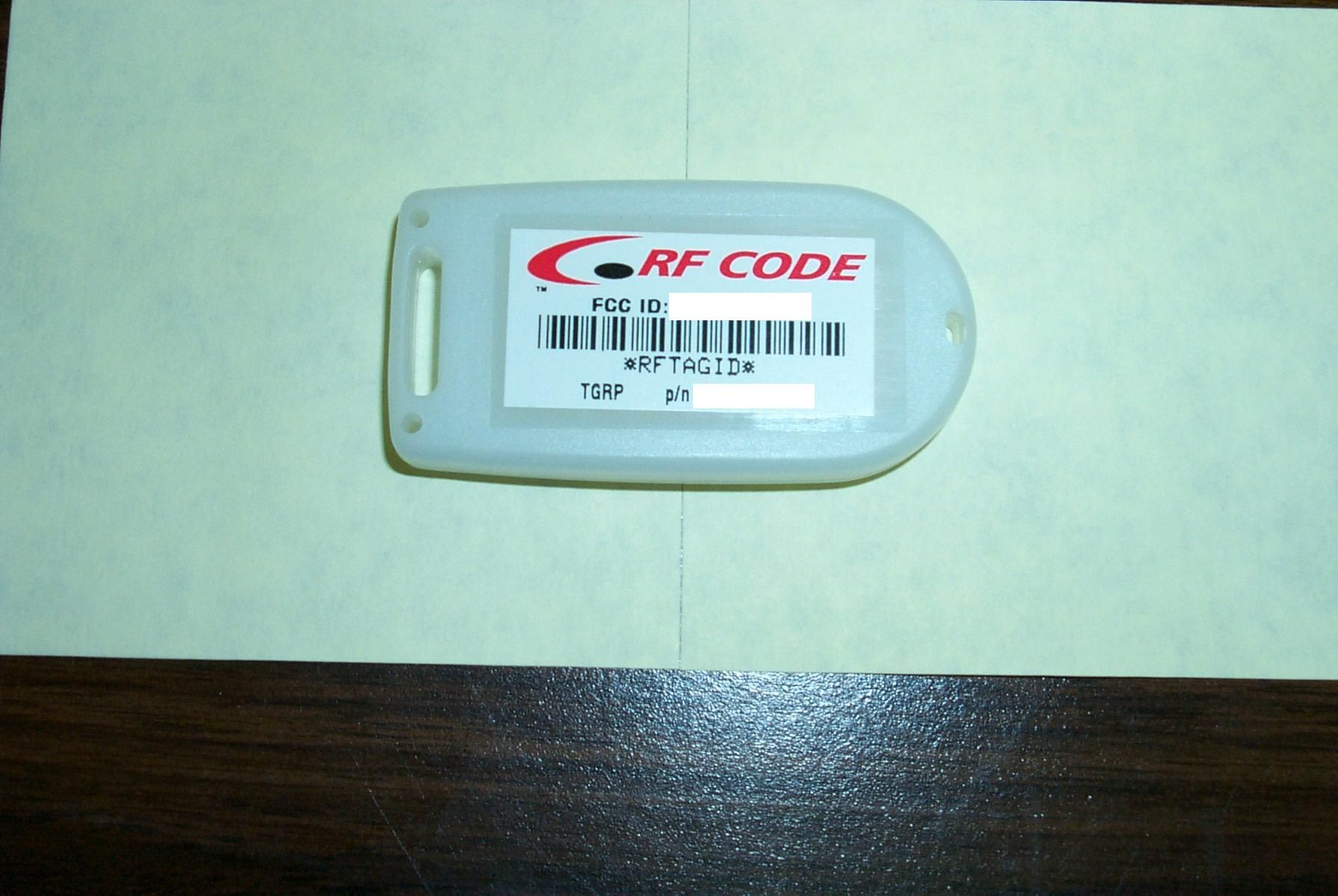
ID Label/Location Info
FCC ID no. N3S2001B02 National Technical Systems, Electromagnetic Compatibility Test ReportPage 1 of 1 1536 E. Valencia Drive, Fullerton, CA 92831-4797; Tel (714) 879-6110; Fax (714) 879-6117 0214-02 1.1 EMC Labels/Marks 1.4-1; Label (size is 1.5 in x 0.75 in.) 1.4-2; Example of “palm-sized” case (actual size) with label installed (FCC ID NO. HERE)
Internal Photos
Test Report No. 174-0976-1-0-N FCC ID No. N3S2001B02 Page 17 of 78 4.2 Circuit Boards and EMC Specific Characteristics This section contains photographs of circuit boards, EMC specific characteristics/components and of modifications required for conformance (refer to paragraph 3.5.1). Printed Circuit Board, Component Side Printed Circuit Board, Foil Side
Test Report
Test Report No. 174-0976-1-0-N Rev A FCC ID No. N3S2001B02 National Technical Systems, Electromagnetic Compatibility Test ReportPage 1 of 36 1536 E. Valencia Drive, Fullerton, CA 92831-4797; Tel (714) 879-6110; Fax (714) 879-6117 0214-02 Electromagnetic Compatibility (EMC) Test Report for RF Code, Inc. Spider TAG Family concerning conformance to the U.S. requirement 47 CFR, Part 15, Subpart C Manufacturer and Applicant for Certification: RF Code, Inc. 1250 South Clearview, Suite 104 Mesa, Arizona 85208 Prepared By:National Technical Systems 1536 E. Valencia Drive Fullerton, California 92831 Issued:September 11, 2001 This report and the information contained herein represent the results of testing test articles identified and selected by the client performed to specifications and/or procedures selected by the client. National Technical Systems (NTS) makes no representations, expressed or implied, that such testing is adequate (or inadequate) to demonstrate efficiency, performance, reliability, or any other characteristic of the articles being tested, or similar products. This report should not be relied upon as an endorsement or certification by NTS of the equipment tested, nor does it represent any statement whatsoever as to its merchantability or fitness of the test article, or similar products, for a particular purpose. This report shall not be reproduced except in full without written approval from NTS. Test Report No. 174-0976-1-0-N Rev A FCC ID No. N3S2001B02 Page 2 of 36 LIST OF RESPONSIBLE PARTIES Test Laboratory Customer The customer listed on page one of this report under “Manufacturer and Applicant for Certification” is responsible for the following with respect to the standards contained in the Test Summary: 1. Ensuring that subsequent product will be manufactured to the same specifications as the sample tested. 2. Ensuring that the product retains electromagnetic compatibility after modifications to its design and/or it manufacturing process. 3. Conducting the appropriate EMC auditing of subsequent product unless conformance herein has been demonstrated by statistical means. If manufacture of the product is by a third party then the customer is strongly encouraged to implement an agreement with his supplier(s) whereby adherence to the above responsibilities is ensured. Test Laboratory Responsibilities With our signatures we, the undersigned, attest to the accuracy of this report and to testing having been conducted with adherence to the appropriate international quality standards and test procedures. Test Report No. 174-0976-1-0-N Rev A FCC ID No. N3S2001B02 Page 3 of 36 TEST SUMMARY This test record demonstrates conformance of the RF Code, Inc. Spider TAG Family with the below listed standard. RegionSpecificationTitle/IntentNotesConforms US47 CFR, Part 15, Sub CRadio Frequency Devices 15.231 (e) Periodic operation in the band 40.66-40.70 MHz and above 70 MHz 15.209 (a) Radiated Emissions Limits: General Requirements Yes Test Report No. 174-0976-1-0-N Rev A FCC ID No. N3S2001B02 Page 4 of 36 TABLE OF CONTENTS 1.0General Information.......................................................................................................6 1.1Product Description................................................................................................6 1.1.1Model Variants...........................................................................................7 1.1.2Accessories Tested With This Product........................................................8 1.1.3Internal, Fundamental Oscillator Frequencies..............................................8 1.2Administrative Data................................................................................................8 1.2.1References..................................................................................................8 1.2.2Test Measurement Instrument Calibration...................................................8 1.3Tested System Details.............................................................................................8 1.3.1Equipment Under Test (EUT).....................................................................8 1.3.2Support Equipment.....................................................................................8 1.4EMC Labels/Marks.................................................................................................9 1.4.1Electrical Schematics..................................................................................9 1.5PCB Layout............................................................................................................9 2.0General Test Methodology and Facility Information..................................................10 2.1Emissions.............................................................................................................10 2.2Basic Calculations................................................................................................11 2.2.1Radiated Emissions Field Strength Calculations........................................11 2.2.2Averaged Levels of Pulsed Emissions Calculations...................................12 2.3Deviation From Standard Test Methods................................................................12 2.4Ambient Conditions During Testing.....................................................................12 2.5Test Facility..........................................................................................................13 3.0Test Configuration........................................................................................................14 3.1EUT Input Power..................................................................................................14 3.2EUT Condition, Configuration and Modes of Operation.......................................14 3.3VDU Mode...........................................................................................................15 3.4EUT Exercis…
Text truncated - open the document above for the full version.
Test Setup Photos
Test Report No. 174-0976-1-0-N Rev A FCC ID No. N3S2001B02 Page 16 of 36 4.0 PHOTOGRAPHS 4.1 Equipment Under Test (EUT) The EUT layout during testing is shown below. The EUT is situated atop an 80cm high wooden table. Radiated Emissions Setup, 30 MHz – 1GHz Radiated Emissions Setup, 1GHz – 10 GHz
Contact Information
Applicant
John Coulthard(Vice President-Manufacturing)
Technical Contact
RF Code, IncJohn Coulthard
[email protected]480-325-4070
1250 S. Clearview, Suite 104 · Mesa, Arizona · United States
Non-Technical Contact
RF Code, IncJohn Coulthard
[email protected]480-325-4070
Test Firm
National Technical Systems (NTS)Ba Nguyen
Technical Specifications
| # | Rule Parts | Frequency Range | Power Output |
|---|---|---|---|
| 1 | 15.231(e) | 303.8 MHz - 303.8 MHz | - |
Other Applications from Addison Hi-Tech Incorporated
N3S2001B03
Nov 14, 2001Scorpion I Tag
Equipment Class
DXX - Part 15 Low Power Communication Device TransmitterN3S2001B01
Oct 18, 1999DXX - Part 15 Low Power Communication Device Transmitter
Equipment Class
DXX - Part 15 Low Power Communication Device Transmitter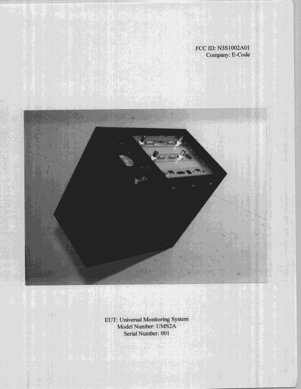
N3S1002A01
Feb 15, 1999Unified Monitoring System
Equipment Class
DSR - Part 15 Remote Control/Security Device Transceiver