N3S2001B03Scorpion I Tag
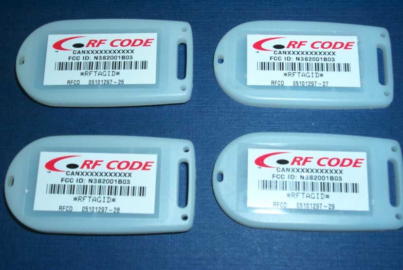
Addison Hi-Tech Incorporated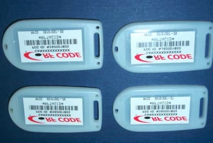
Click to zoom
Application Details
- Equipment Class
- DXX - Part 15 Low Power Communication Device Transmitter
- Date of Grant
- Nov 14, 2001
- Application Purpose
- Original Equipment
- Date of Application
- Nov 14, 2001
- Equipment Note
- Scorpion I Tag
- Frequency Range
- 303.70400000 - 303.92200000
- Company
- Addison Hi-Tech Incorporated
- Country
- United States
Documents & Files
Document Text
Text extracted from the exhibit documents filed with the FCC. Open a document above to read the original.
Users Manual
Scorpion I Reader User’s Guide RF Code, Inc. Publication: 03801674-01 Issue DateCommentRevision November 8, 2001Initial Release00 is the trademark of RF Code, Inc. 1250 South Clearview Ave. Mesa, AZ 85208 (480) 969-2828 www.rfcode.com Copyright 2001 RF Code, Inc. All Rights Reserved Scorpion I Reader II Copyright 2001 RF Code, Inc. FCC Certification Note: This equipment has been tested and found to comply with the limits for a Class A digital device, pursuant to part 15 of the FCC rules. These limits are designed to provide reasonable protection against harmful interference when the equipment is operated in a commercial environment. This equipment generates, uses and can radiate radio frequency energy and, if not installed and used in accordance with the instruction manual, may cause harmful interference to radio communications. Operation of this equipment in a residential area is likely to cause harmful interference in which case the user will be required to correct the interference at his own expense. The Scorpion I’s two major components are independently certified and comply with Federal Communications Commission (FCC) rules, part 15. 1. This Scorpion I Reader complies with part 15 of the FCC rules. Operation is subject to the following two conditions: (1) this device may not cause harmful interference, and (2) this device must accept any interference received, including interference that may cause undesired operation. 2. The system operates by using Scorpion I tags that have been certified or are in the certification process. These devices comply with part 15 of the FCC rules. Operation is subject to the following two conditions: (1) these devices may not cause harmful interference, and (2) these devices must accept any interference received, including interference that may cause undesired operation. a. FCC ID: N3S2001B01 for standard 7 second Spider Tag P/N: 05101297-06. b. FCC ID: N3S2001B02 for 13 second Spider Tag P/N: 05101297-07, for 25 second Spider Tag P/N: 05101297-20, for 50 second Spider Tag P/N: 05101297-21. c. FCC ID: N3S2001B03 for 2 second Scorpion I Tag P/N: 05101297-26, for 5 second Scorpion I Tag P/N: 05101297-27, for 10 second Scorpion I Tag P/N: 05101297-28, for 15 second Scorpion I Tag P/N: 05101297- 29. d. FCC IDs: N3S2001B04/5 have been reserved for Scorpion I Tags w/motion sensors and Scorpion II tags, respectively. The Emissions Designator for 1. is 400KL1D and for 2. and 3. it is 400KP1D. Warning: Changes or modifications not expressly approved by the party responsible for compliance could void the user's authority to operate the equipment. Scorpion I Reader Copyright 2001 RF Code, Inc. III Table of Contents 1INTRODUCTION...............................................................................................................1 2PURPOSE............................................................................................................................1 3SCOPE..................................................................................................................................1 4SCORPION I READER......................................................................................................2 4.1S CORPION I R EADER P HYSIC AL I/O................................................................................2 4.2S CORPION I R EADER I NT ERNAL S ETTINGS ......................................................................5 4.3S CORPION I R EADER A NTENNAS ....................................................................................7 4.4S CORPION I R EADER E NVIRONMENTAL L IMITS ..............................................................8 4.5S CORPION I R EADER M OUNTING ....................................................................................8 4.6S CORPION T AGS .............................................................................................................9 List of Figures Figure 1 Scorpion I Reader (Front View) ..........................................................................2 Figure 2 Scorpion I (Rear View) .....................................................................................3 Figure 3 Scorpion I Internal Configuration Points ..............................................................5 Figure 4 Scorpion I Physical Mounting Dimensions ...........................................................9 Scorpion I Reader Copyright 2001 RF Code, Inc. 1 1 Introduction The RF Code Scorpion I System is an RFID monitoring system designed to report tags within defined reader operating ranges. The system utilizes “beacon” tags that periodically report their presence with an encoded radio transmission. The Scorpion I Reader is a dual channel radio receiver tuned to the Scorpion I Tag transmission frequency. The Scorpion I includes a Client Bridge as the interface between the Scorpion I Reader and an Ethernet network. The reader receives the message and decodes the tag’s identity each time the tag transmits. The reader sends the tag identity information through the Client Bridge to the RF Code Concentrator LI software application for processing. The Client Bridge can be configured to operate as a wired connection to the Ethernet 10/100 network, using an RJ-45 connector, or using an IEEE 802.11b wireless connection to the host computer. 2 Purpose This manual provides instructions for the Scorpion I Reader setup and operation. The Scorpion I Reader has different modes of operation and optional functions that are user-selected, depending on the system’s operational requirements. 3 Scope The instructions in this manual show how to configure the Scorpion I Reader for physical options contained within the device itself. Operational Instructions for the Scorpion I System using RF Code’s Concentrator LI software are found in the Concentrator LI User’s Guide; RF Code publication IS1007 Scorpion I IIIAR Reader 2 Copyright 2001 RF Code, Inc. 4 Scorpion I Reader The Scorpion I Reader cont…
Text truncated - open the document above for the full version.
Cover Letter(s)
1250 S. Clearview Avenue, Mesa, AZ 85208-3378, Phone: (480) 969-2828, Fax: (480) 325-4029 October 10, 2001 Federal Communications Commission 7435 Oakland Mills Road, Columbia, MD 21046 Gentlemen: This letter is to comply with Section 0.457(d)(i) pertaining to confidential material. RF Code, Inc. would like the following documents regarding this submission for FCC ID N3S2001B03 to be kept confidential. 1. Circuit Schematic Diagram 2. Spider Tag Block Diagram 3. Description of Circuit Functions and Device Operation The above material contains trade secrets or technical data, which would customarily be guarded from competitors. We do not want these documents to be accessible to the general public. Signed: John J. Coulthard VP Product EngineeringOctober 10, 2001 Company OfficerTitleDate
Test Report
Page 1 of 28 Report No.: FC01-074A RF CODE, INC. ADDENDUM TO FC01-074 FOR THE SCORPION I, 05101297-26/05101297-27/05101297-28/05101297-29 FCC PART 15 SUBPART C SECTION 15.209 COMPLIANCE DATE OF ISSUE: NOVEMBER 15, 2001 PREPARED FOR: RF Code, Inc 1250 South Clearview, Suite 104 Mesa, AZ 85208 PREPARED BY: Joyce Walker CKC Laboratories, Inc. 5473A Clouds Rest Mariposa, CA 95338 P.O. No.: 101-2993 W.O. No.: 77783 Date of test: September 28 - October 2, 2001 Report No.: FC01-074A This report contains a total of 28 pages and may be reproduced in full only. Partial reproduction may only be done with the written consent of CKC Laboratories, Inc. Page 2 of 28 Report No.: FC01-074A TABLE OF CONTENTS Administrative Information ............................................................................................. 3 Summary of Results......................................................................................................... 4 Modifications Required for Compliance ......................................................................... 4 Approvals......................................................................................................................... 4 Equipment Under Test (EUT) Description...................................................................... 5 Equipment Under Test..................................................................................................... 5 Peripheral Devices ........................................................................................................... 5 15.33 Frequency Range Tested ....................................................................................... 5 EUT Operating Frequency............................................................................................... 5 Temperature and Humidity During Testing .................................................................... 5 Report of Measurements.................................................................................................. 6 Table 1: Fundamental Radiated Emission Levels ............................................... 6 Table 2: Six Highest Radiated Emission Levels: 0.01 - 30 MHz........................ 7 Table 3: Highest Radiated Emission Levels: 30 - 1000 MHz ............................. 8 Table 4: Six Highest Radiated Emission Levels: 1 - 4 GHz ............................... 9 Measurement Uncertainty................................................................................................ 10 EUT Setup .......................................................................................................................10 Correction Factors ........................................................................................................... 10 Table A: Sample Calculations ............................................................................. 10 Test Instrumentation and Analyzer Settings.................................................................... 12 Table B: 15.35 Analyzer Bandwidth Settings Per Frequency Range.................. 12 Spectrum Analyzer Detector Functions............................................................... 13 Peak ......................................................................................................... 13 Quasi-Peak............................................................................................... 13 Average.................................................................................................... 13 EUT Testing ....................................................................................................................14 Radiated Emissions ............................................................................................. 14 Transmitter Characteristics.............................................................................................. 15 15.203 Antenna Requirements ............................................................................ 15 15.205 Restricted Bands ...................................................................................... 15 Appendix A: Test Setup Photos ...................................................................................... 16 Photograph Showing Radiated Emissions ........................................................... 17 Photograph Showing Radiated Emissions ........................................................... 18 Photograph Showing Radiated Emissions ........................................................... 19 Appendix B: Measurement Data Sheets .......................................................................... 20 Page 3 of 28 Report No.: FC01-074A CKC Laboratories, Inc. has received Certificates of Accreditation from the following agencies: A2LA (USA); DATech (Germany); BSMI (Taiwan); Nemko (Norway); and GOST (Russia). CKC Laboratories, Inc has received test site Registration Acceptance from the following agencies: FCC (USA); VCCI (Japan); and Industry Canada. CKC Laboratories, Inc. has received Letters of Acceptance through an MRA for the following agencies: ACA/NATA (Australia); SABS (South Africa); SWEDAC (Sweden); Radio Communications Agency (RA); HOKLAS (Hong Kong); Bakom (Swiss); BIPT (Belgium); Denmark Telestyrelsen; RvA (Netherlands); SEE (Luxembourg) SITTEL (Bolivia); and UKAS (UK). ADMINISTRATIVE INFORMATION DATE OF TEST: September 28 - October 2, 2001 DATE OF RECEIPT: September 28, 2001 PURPOSE OF TEST: To demonstrate the compliance of the Scorpion I, 05101297-26/05101297-27/05101297- 28/05101297-29 with the requirements for FCC Part 15 Subpart C Section 15.209 devices. The addendum is to correct the following clerical errors; reference to conducted testing, biconilog antenna and incorrect bandwidth settings on page 12. TEST METHOD: ANSI C63.4 (1992) MANUFACTURER: RF Code, Inc 1250 South Clearview, Suite 104 Mesa, AZ 85208 REPRESENTATIVE: John Coulthard TEST LOCATION: CKC Laboratories, Inc. 5473A Clouds Rest Mariposa, …
Text truncated - open the document above for the full version.
Test Setup Photos
PHOTOGRAPH SHOWING RADIATED EMISSIONS Radiated Emissions - Front View Using Bicon Antenna PHOTOGRAPH SHOWING RADIATED EMISSIONS Radiated Emissions - Back View Using Log Periodic Antenna PHOTOGRAPH SHOWING RADIATED EMISSIONS Radiated Emissions - Back View Using Bicon Antenna
Contact Information
Applicant
John Coulthard(Vice President-Manufacturing)
Technical Contact
CKC Laboratories, Inc.Joyce Walker
[email protected]800.500.4362
5473A Clouds Rest · Mariposa, California · United States
Non-Technical Contact
CKC Laboratories, Inc.Joyce Walker
[email protected]800.500.4362
Test Firm
CKC Laboratories, Inc.Steve Behm
Technical Specifications
| # | Rule Parts | Frequency Range | Power Output |
|---|---|---|---|
| 1 | 15C | 303.704 MHz - 303.922 MHz | - |
Other Applications from Addison Hi-Tech Incorporated
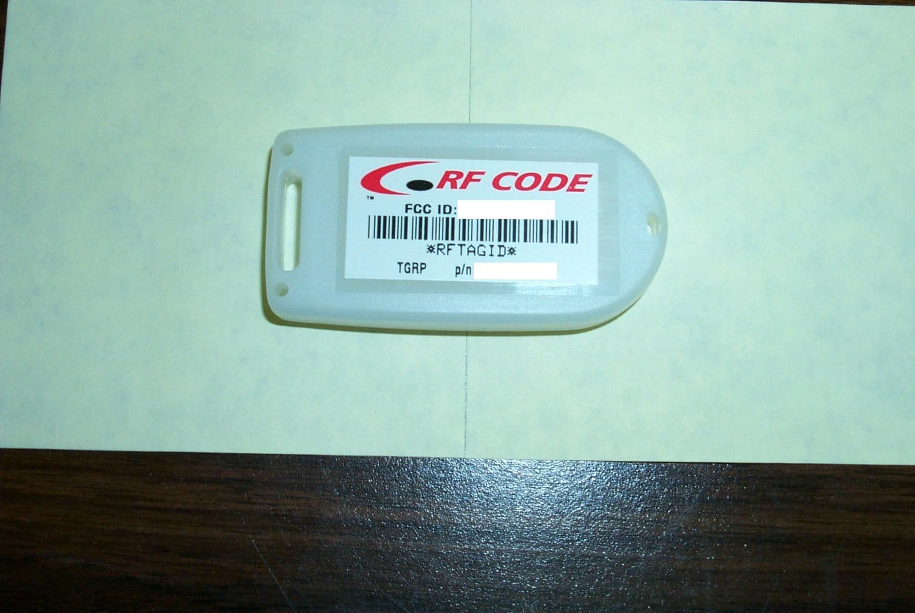
N3S2001B02
Sep 16, 2001Remote device identification transmitter
Equipment Class
DSC - Part 15 Security/Remote Control TransmitterN3S2001B01
Oct 18, 1999DXX - Part 15 Low Power Communication Device Transmitter
Equipment Class
DXX - Part 15 Low Power Communication Device Transmitter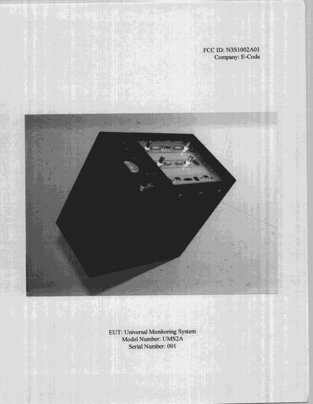
N3S1002A01
Feb 15, 1999Unified Monitoring System
Equipment Class
DSR - Part 15 Remote Control/Security Device Transceiver