N4CPOSIPIN
Position Technology Inc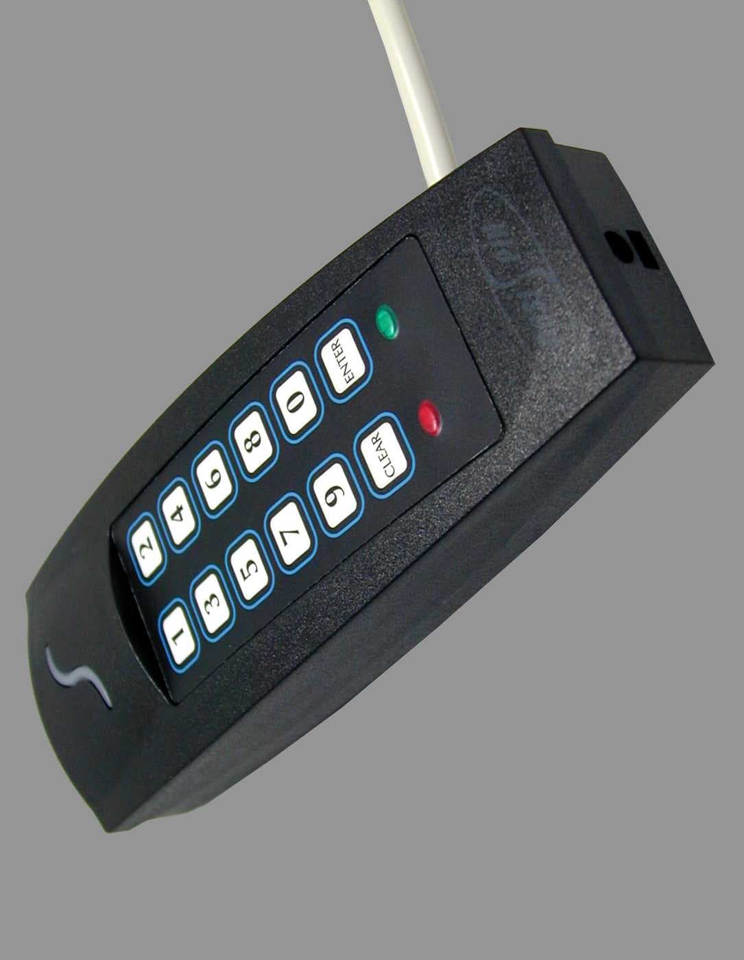
Click to zoom
Application Details
- Equipment Class
- FDS - Part 15 Field Disturbance Sensor
- Date of Grant
- Jun 13, 2002
- Application Purpose
- Original Equipment
- Date of Application
- May 07, 2002
- Frequency Range
- 0.12500000 - 0.12500000
- Company
- Position Technology Inc
- Country
- Canada
Documents & Files
Document Text
Text extracted from the exhibit documents filed with the FCC. Open a document above to read the original.
Users Manual
PIN and Proximity Reader For Access Control Systems (CR-R885-A) Installation and Operating Instructions Version 1.0 PosiPin 1 TABLE OF CONTENTS Installation ............................................................................ 2 Technical Specifications ....................................................... 3 Feedback .............................................................................. 5 Programming ........................................................................ 5 Card/Code Options ............................................................... 6 Keypad Communication Format ........................................... 6 Transfer Limit for 4-bits Buffered Format ............................. 7 Display on Card Read .......................................................... 7 Keypad Lockout .................................................................... 8 26-bit Wiegand Card Family Code Setting ........................... 8 Reader’s Interface ................................................................ 9 Check-in Supervision ........................................................... 9 Buzzer Setting .................................................................... 10 Face Light Intensity ............................................................ 10 Face Light Operation .......................................................... 10 Face Light Colour ............................................................... 10 Changing the Installer Code ............................................... 11 Panic Alarm ........................................................................ 11 Resetting to Default ............................................................ 11 Card Presentation Test ...................................................... 12 Warranty ............................................................................. 12 2 Installation and Operating Instructions INSTALLATION For PosiPin to function correctly with the access control system, some programming may be required in the controller or control panel of the host system. For further instructions, refer to the appropriate manual. Only explanations directly concerning PosiPin’s programming will be included in this manual. Selecting an Installation Site: • Avoid wiring the PosiPin cables in the same conduit as AC power cables, lock power or signal wiring. • Reader wiring must remain a minimum of 30cm (12in) away from other wiring, such as wiring for AC power, computer data, telephones, electric locks, etc. • Avoid sites within 1.1m (3.5ft) of computer monitors or CRTs. • Avoid sites near sources of broad spectrum EMI noise, such as motors, pumps, generators, DC to AC converters, AC switching relays, power supplies, and light dimmers. • Avoid sites near potential sources of RF signals, such as cellular phones, two-way radios, etc. Mounting and Wiring After selecting a site for the PosiPin, use the mounting plate as a guide to drill two holes to secure the mounting plate and a hole for the cable 0.95cm to 2.54cm (0.375in to 1in) wide. Place a grommet around the edge of the hole for the cable. Prepare PosiPin’s cable by cutting the cable jacket back 3.175cm (1.25in) and stripping the wires back 0.635cm (0.25in). Splice PosiPin’s wires with a recommended cable wire. Route the cable to the controller and connect as shown in Figure 1: Connection drawing on page 4. PosiPin 3 Mounting on Metal Surfaces Although the read range may slightly decrease, PosiPin can be mounted on metal. However, do not box in or surround the card reader with any kind of metal. If the reader must be installed in a metal enclosure, ensure that the face of the card reader is not covered and that at least 1.6" (4cm) remain between the card reader and the metal on all sides of the card reader. TECHNICAL SPECIFICATIONS Input Voltage:Typical: 13.8Vdc, min.: 11.0Vdc, max: 14.5Vdc Input Current:Typical: 65mA @ 12.5Vdc, with card: 105mA Consumption:Typical: 812mW @ 12.5Vdc, with card 1.31mW Frequency:Exciter Field: 125KHz Pulse Modulated, receive low: 12.500KHz, Receive high: 15.625KHz Operating Temp:-35°C (-31°F) to +65°C (+149°F) Output formats:Reader: 26- and 37-bit Wiegand Keypad: 8-, 26- and 37-bit Wiegand, 4-bit with or without parity, and 4 bits buffered with or without parity Cable Distance:152.4m (500ft.) Suggested Cables: 22AWG, 0.8mm, Multi-conductor, Alpha 5196, 5198 18AWG, 1.2mm, Multi-conductor, Alpha 5386, 5388 Belden 9553, 18AWG, 6-conductor, stranded w/ overall shield Indicators:Beeper, red LED, green LED, red or green Face Light Weight:280g (9.8 oz.) Material:Black, UV resistant, ABS plastic Dimensions:99.5mm (5.75in.) x 118.5mm (2in.) x 19.5mm (1in.) 4 Installation and Operating Instructions Figure 1: Connection drawing PosiPin 5 FEEDBACK Visual Feedback: When information is entered on the reader’s keypad, the red and/or green LEDs will flash, remain constant or extinguish depending on the operation. Confirmation Beep: When an operation is successfully entered, the reader emits a rapid series of beep tones (“beep-beep-beep- beep-beep”). Rejection Beep: When the system reverts to a previous status or an operation is incorrectly entered, the reader emits one long beep tone (“beeeeeeeeeep”). PROGRAMMING Ensure that corresponding programming is completed in the control panel or controller connected to the PosiPin. To program: 1. Press and hold the [ CLEAR ] key for 4 seconds. The reader emits a confirmation beep and the green LED illuminates. 2. Enter the [ INSTALLER CODE ]. Press the [ ENTER ] key. (default:000000) Reader emits a confirmation beep and the green LED flashes. 3. Enter the 3-digit [ SECTION ]. Press the [ ENTER ] key. Reader emits a confirmation beep and the green LED stops flashing. 4. Enter the required [ DATA ]. Press the [ ENTER ] key. The reader emits a confirmation beep and the green LED flashes. 5. To program another section, repeat steps 3 and 4. To exit programming mode, press and hold the [ C…
Text truncated - open the document above for the full version.
Users Manual
PIN and Proximity Reader Stand-alone System (CR-R885-S and CR-R885-SB) Installation and Operating Instructions PosiPin 1 TABLE OF CONTENTS Installation .......................................................................... 2 Mounting and Wiring ................................................................ 2 Mounting on Metal Surfaces ..................................................... 2 Technical Specifications ........................................................... 3 Feedback .................................................................................. 5 Resetting to Default .................................................................. 5 Card Presentation Test ............................................................ 5 System Programming ........................................................ 6 Section [001] Card/Code Options ............................................. 6 Section [002] Door Lock Control .............................................. 7 Section [003] Access Granted Options .................................... 7 Section [004] Display on Card Read ........................................ 8 Section [005] Keypad Lockout .................................................. 9 Section [101] Buzzer Setting .................................................... 9 Section [102] Face Light Intensity ............................................ 9 Section [103] Face Light Operation .......................................... 9 Section [104] Face Light Colour ............................................. 10 Section [200] Changing the Installer Code ............................. 10 Resetting the Installer and Master Codes to Default .............. 10 Master Programming ....................................................... 11 Sections [201] and [202] Changing the Master Codes ........... 11 Section [203] User Code Programming .................................. 11 Deleting a User Code ............................................................. 13 Section [204] User Code Reset .............................................. 14 User Operation ................................................................. 15 User Access ........................................................................... 15 Panic Alarm ............................................................................ 16 User Code Table ............................................................... 17 Warranty ............................................................................ 19 2 Installation and Operating Instructions INSTALLATION To select an installation site: • Avoid wiring the PosiPin cables in the same conduit as AC power cables, lock power or signal wiring. • Reader wiring must remain a minimum of 30cm (12in) away from other wiring, such as wiring for AC power, computer data, telephones, electric locks, etc. • Avoid sites within 1.1m (3.5ft) of computer monitors or CRTs. • Avoid sites near sources of broad spectrum EMI noise, such as motors, pumps, generators, DC to AC converters, AC switching relays, power supplies and light dimmers. • Avoid sites near potential sources of RF signals, such as cellular phones, two-way radios, etc. MOUNTING AND WIRING Use the mounting plate as a guide to drill two holes to secure the mounting plate and a hole for the cable 0.95cm to 2.54cm (0.375in to 1in) wide. Place a grommet around the edge of the hole for the cable. Prepare PosiPin’s cable by cutting the cable jacket back 3.175cm (1.25in) and stripping the wires back 0.635cm (0.25in). Splice PosiPin’s wires with a recommended cable wire (see page 5) and connect as shown in Figure 1 on page 4. MOUNTING ON METAL SURFACES Although the read range may decrease, PosiPin can be mounted on metal. However, do not box in or surround the card reader with any kind of metal. If the reader must be installed in a metal enclosure, ensure that the face of the card reader is not covered and that at least 1.6" (4cm) remain between the card reader and the metal on all sides of the card reader. PosiPin 3 TECHNICAL SPECIFICATIONS Input Voltage:Typical: 13.8VDC, min.: 11.0VDC, max: 14.5VDC Input Current:Typical: 65mA @ 12.5VDC, with card: 105mA Consumption:Typical: 812mW @ 12.5VDC, with card 1.31mW Frequency:Exciter Field: 125KHz Pulse Modulated, receive low: 12.500KHz, Receive high: 15.625KHz Operating Temp:-35°C (-31°F) to +65°C (+149°F) Cable Distance:152.4m (500ft.) Suggested Cables: 22AWG, 0.8mm, Multi-conductor, Alpha 5196, 5198 18AWG, 1.2mm, Multi-conductor, Alpha 5386, 5388 Belden 9553, 18AWG, 6-conductor, stranded w/ overall shield Indicators:Beeper, red LED and green LED For CR-R885-S: red and green Face Light For CR-R885-SB: blue and green Face Light Weight:280g (9.8 oz.) Material:Black, UV resistant, ABS plastic Dimensions:99.5mm (5.75in.) x 118.5mm (2in.) x 19.5mm (1in.) 4 Installation and Operating Instructions Figure 1: Connection drawing PosiPin 5 FEEDBACK Depending on the programming mode chosen, the feedback will differ. In the section System Programming on page 6 and Master Programming on page 11, the combinations of visual feedback and beep tones are specified step by step. Visual Feedback: When information is entered on the reader’s keypad, the red and/or green LEDs will flash, remain constant or extinguish depending on the step reached in programming. Confirmation Beep: When an operation is successfully entered, the reader emits a rapid series of beep tones (“beep-beep-beep-beep-beep”). Rejection Beep: When the system reverts to a previous status or an operation is incorrectly entered, the reader emits one long beep tone (“beeeeeeeeeep”). RESETTING TO DEFAULT To reset all sections to factory defaults, disconnect reader’s power supply. Press and hold the [1] and [2] keys simultaneously while re-connecting its power supply. Sections are reset when the reader emits a confirmation beep. CARD PRESENTATION TEST Place the card parallel to the PosiPin reader (as shown in the figure) and move it towar…
Text truncated - open the document above for the full version.
Attestation Statements
Position Technology 780 INDUSTRIAL BLVD • ST-EUSTACHE (MONTREAL), QUEBEC, CANADA • J7R 5V3 Telephone: (450) 491-7444 • Fax: (450) 491-2313 Monday, March 18, 2002 Federal Communications Commission 7435 Oakland Mills Road Columbia, MD 21046 USA Authority to Act as Agent to the Federal Communications Commission On our behalf, I appoint Nemko Canada to act as agent in the preparation of this application for equipment authorization to the Federal Communications Commission. I certify that submitted Exhibits properly describe the device or system for which equipment authorization is sought. I also certify that each unit manufactured, imported or marketed, as defined in the Commission’s regulations will have affixed to it a label identical to that submitted for approval with this application. Agency agreement expiration date: March 18, 2003 If you have any questions or comments, please do not hesitate to contact me, Marc Bertrand Certification Manager Position Technology inc. e-mail: [email protected]
Attestation Statements
Position Technology 780 INDUSTRIAL BLVD • ST-EUSTACHE (MONTREAL), QUEBEC, CANADA • J7R 5V3 Telephone: (450) 491-7444 • Fax: (450) 491-2313 Monday, March 18, 2002 Office of Engineering & Technology Federal Communications Commission Washington, D.C. 20554 Subject: Request for continuous confidentiality of technical information per Sections 0.459 and 0.457 (d) (2) (I) of CFR 47. FCC ID: N4CPOSIPIN To Whom It May Concern: Position Technology inc. is hereby filing this request for continuous confidentiality of the specified items submitted with the application for certification (Form 731) with proposed identifier N4CPOSIPIN The technical documentation for which continuous confidentiality is sought is: 1. Schematic diagrams, PCB Layers 2. Components List (BOM) 3. Technical Description This technical documentation is a part of the material supporting the Form 731 application for certification, which this request for confidentiality accompanies. The schematic diagrams disclose proprietary information and technical data that Position Technology inc. would guard from its competitors and would not make available to the public. This proprietary information constitutes a trade secret and is not a part of the product documentation that would be made available to the customers of Position Technology inc.. It would be potentially injurious to Position Technology inc. in the development of this innovative proprietary product to make available for public disclosure the trade secret technical information specified in this request. If you have any questions or comments, please do not hesitate to contact me, Marc Bertrand Certification Manager Position Technology inc. e-mail: [email protected]
Cover Letter(s)
Position Technology 780 INDUSTRIAL BLVD • ST- EUSTACHE (MONTREAL), QUEBEC, CANADA • J7R 5V3 Telephone: (450) 491-7444 • Fax: (450) 491-2313 Monday, March 18, 2002 To Whom It May Concern: DIFFERENCES BETWEEN POSIPIN-S (CR-R885-S) and POSIPIN-A (CR-R885-A) Both models are identical except the CR-R885-A communicates with and alarm and/or access system, while the CR-R885-S works stand-alone. It is important to point out that both versions may be offered with a blue LED version, CR-R885-BL (CR-R885-A in blue version) and CR-R885-SB (stand-alone in blue version). If you have any questions or comments, please do not hesitate to contact me, Marc Bertrand Certification Manager Position Technology inc. e-mail: [email protected]
Test Report
Master: PT15209 Date: December 12, 2001 Test Report:2W04779 Applicant:Position Technology Inc. 780 Industrial Blvd. Ste-Eustache, Quebec J7R 5V3 Equipment Under Test:CR-R885-A & CR-R885-S (EUT)Pin & Proximity Readers FCC ID: N4CPOSIPIN In Accordance With:FCC Part 15, Subpart C, 15.209 Tested By:Nemko Canada Inc. 303 River Road, R.R. 5 Ottawa, Ontario K1V 1H2 Authorized By: J. Harrington, RF Group Manager Date:8 May 2002 Total Number of Pages:11 Nemko Canada Inc.FCC PART 15, SUBPART C, 15.209 PROJECT NO.: 2W04779 EQUIPMENT: CR-R885-A & CR-R885-S Page 2 of 11 Table Of Contents Section 1. Summary Of Test Results.....................................................................................3 Section 2. General Equipment Specification........................................................................5 Section 3. Radiated Emissions...............................................................................................7 Section 4. Block Diagrams...................................................................................................10 Section 5. Test Equipment List...........................................................................................11 Nemko Canada Inc.FCC PART 15, SUBPART C, 15.209 PROJECT NO.: 2W04779 EQUIPMENT: CR-R885-A & CR-R885-S Page 3 of 11 Section 1.Summary Of Test Results General All measurements are traceable to national standards. These tests were conducted on a sample of the equipment for the purpose of demonstrating compliance with FCC Part 15, Subpart C for low power devices. All tests were conducted using measurement procedure ANSI C63.4-1992. Radiated Emissions were made on an open area test site. A description of the test facility in on file with the FCC. THIS TEST REPORT RELATES ONLY TO THE ITEM(S) TESTED. THE FOLLOWING DEVIATIONS FROM, ADDITIONS TO, OR EXCLUSIONS FROM THE TEST SPECIFICATIONS HAVE BEEN MADE. See “ Summary of Test Data”. TESTED BY: Glen Westwell, Wireless Technologist DATE: 8 May 2002 Nemko Canada Inc., a testing laboratory, is accredited by the Standards Council of Canada. The tests included in this report are within the scope of this accreditation. The results apply only to the samples tested. Nemko Canada Inc. authorizes the above named company to reproduce this report provided it is reproduced in its entirety and for use by the company’s employees only. Any use which a third party makes of this report, or any reliance on or decisions to be made based on it, are the responsibility of such third parties. Nemko Canada Inc. accepts no responsibility for damages, if any, suffered by any third party as a result of decisions made or actions based on this report. This report applies only to the items tested. Nemko Canada Inc.FCC PART 15, SUBPART C, 15.209 PROJECT NO.: 2W04779 EQUIPMENT: CR-R885-A & CR-R885-S Page 4 of 11 Summary Of Test Data Name Of TestPara. No.Result Powerline Conducted Emissions15.207N/A Radiated Emissions15.209Complies Footnotes For N/A’s:12 VDC external power supply. Test Conditions: IndoorTemperature:24 °C Humidity:38 % OutdoorTemperature:-5 °C Humidity:44 % Nemko Canada Inc.FCC PART 15, SUBPART C, 15.209 PROJECT NO.: 2W04779 EQUIPMENT: CR-R885-A & CR-R885-S Page 5 of 11 Section 2.General Equipment Specification Manufacturer: Position Technology Inc. Model No.: CR-R885-A CR-R885-S Serial No.: None Date Received In Laboratory: Nov. 16, 2001 Nemko Identification No.: Item #17 & 18 Frequency: 125 kHz Modulation: Pulse Modulated Emission Designator: 10K0PON Both models are electrically identical and differ only in software features and functions. Measurements were made on the model CR-R885-S. Nemko Canada Inc.FCC PART 15, SUBPART C, 15.209 PROJECT NO.: 2W04779 EQUIPMENT: CR-R885-A & CR-R885-S Page 6 of 11 Nemko Canada Inc.FCC PART 15, SUBPART C, 15.209 PROJECT NO.: 2W04779 EQUIPMENT: CR-R885-A & CR-R885-S Page 7 of 11 Section 3.Radiated Emissions Para. No.: 15.209 Test Performed By: Russell GrantDate of Test: August 17, 2001 Minimum Standard: Fundamental (MHz) Field Strength (μμV/m) Field Strength (dBμμV) 0.009 - 0.4902400/F(kHz) @ 300m— 0.490 - 1.70524000/F(kHz) @ 30m— 1.705 - 3030 @ 30m— 30 - 8810040.0 88 - 21615043.5 216 - 96020046.0 Above 96050054.0 Test Results:Complies. Measurement Data:See attached table. Nemko Canada Inc.FCC PART 15, SUBPART C, 15.209 PROJECT NO.: 2W04779 EQUIPMENT: CR-R885-A & CR-R885-S Page 8 of 11 Test Data - Radiated Emissions Frequency of Emission (MHz) Received Signal (dBuV/m@10m) Limit @ 300m (dBuV/m) Limit @10m (dBuV/m) Margin (dB) 0.1255325.755.22.2 Frequency of Emission (MHz) Received Signal (dBuV/m@2m) Received Signal (dBuV/m@4m) Extrapolated Signal (dBuV/m@300m) Limit (dBuV/m)Margin (dB) 0.25069.052.0 -53.919.673.6 0.37564.049.0 -44.016.160.1 0.50059.040.0 -78.333.6111.9 0.62554.038.0 -61.631.793.9 0.75050.035.0 -58.430.188.5 0.87548.032.0 -67.628.896.4 1.00037.027.0 -35.327.662.9 1.37540.026.0 -61.224.886 1.50038.026.0 -48.824.172.9 1.62536.025.0 -43.423.466.8 1.75035.026.0 -30.129.559.6 1.87534.030.0 5.129.524.4 Note:Emissions measured at 2 m & 4m. dB/decade extrapolation using field strength measurement from 2 to4m. Nemko Canada Inc.FCC PART 15, SUBPART C, 15.209 PROJECT NO.: 2W04779 EQUIPMENT: CR-R885-A & CR-R885-S Page 9 of 11 Radiated Emissions- Photographs Nemko Canada Inc.FCC PART 15, SUBPART C, 15.209 PROJECT NO.: 2W04779 EQUIPMENT: CR-R885-A & CR-R885-S Page 10 of 11 Section 4.Block Diagrams Radiated Prescan SPECTRUM ANALYZER AND PLOTTER OR TEST RECEIVER COMPUTER ANTENNA EUT SHIELDED ROOM Test Site For Radiated Emissions 3 METERS E.U.T. NON-CONDUCTING TURN-TABLE 0.8 METER VARIABLE SEARCH HEIGHT (1 TO 4 m) TO TEST RECEIVER/SPECTRUM ANALYZER SEARCH ANTENNA Nemko Canada Inc.FCC PART 15, SUBPART C, 15.209 PROJECT NO.: 2W04779 EQUIPMENT: CR-R885-A & CR-R885-S Page 11 of 11 Section 5.Test Equipment List CAL CYCLE EQUIPMENTMANUFACTURERMODELSERIALLAST CAL.NEXT CAL. 1 YearSpectrum AnalyzerHewlett Packard8565EFA000981June 08/01June 08/02 1 YearReceiverRohde & S…
Text truncated - open the document above for the full version.
Contact Information
Applicant
Marc Bertrand(Certification Manager)
Technical Contact
Nemko Canada Inc.Ruby Dulmage
[email protected]613-737-9680
303 River Road, R.R. 5 · Ottawa, Ontario · Canada
Non-Technical Contact
Nemko Canada Inc.Ruby Dulmage
[email protected]613-737-9680
Test Firm
Nemko Canada Inc.Stuart Beck
Technical Specifications
| # | Rule Parts | Frequency Range | Power Output |
|---|---|---|---|
| 1 | 15C | 0.125 MHz - 0.125 MHz | - |
Other Applications from Position Technology Inc
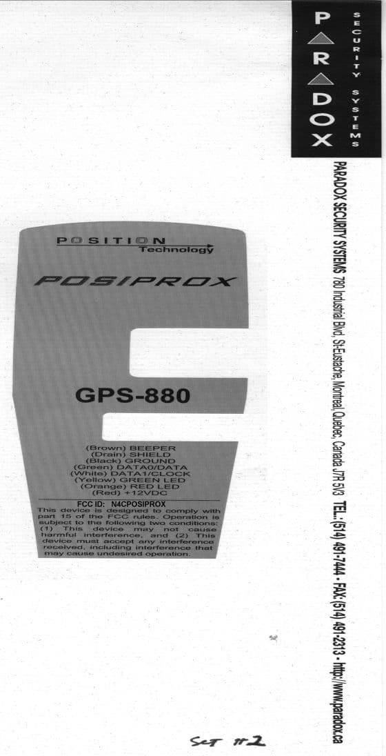
N4CPOSIPROX
May 18, 1999POSI PROX GPS-880 SERIES PROXIMITY READER
Equipment Class
DCD - Part 15 Low Power Transmitter Below 1705 kHz