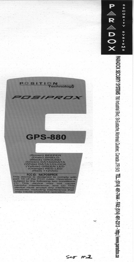
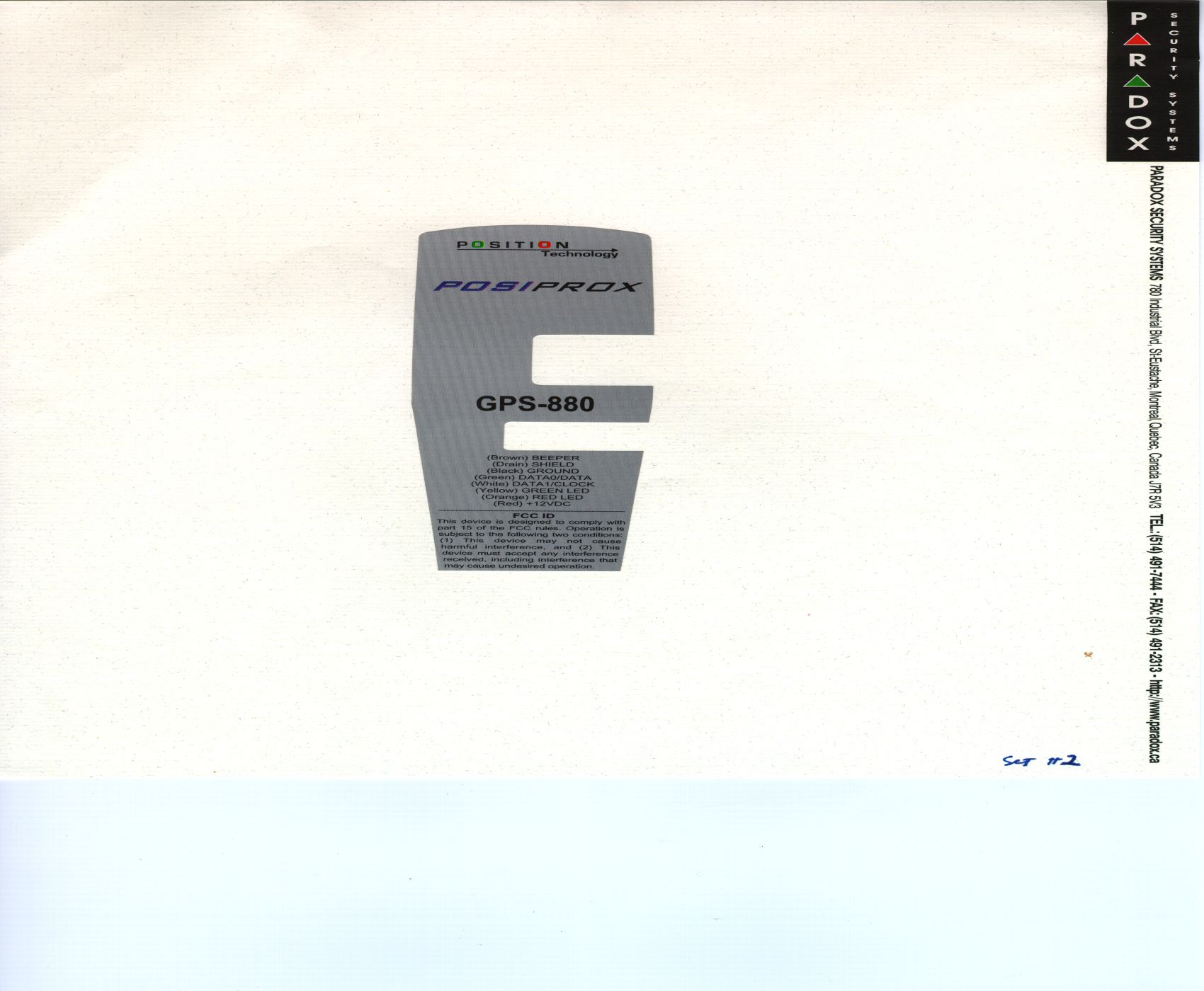
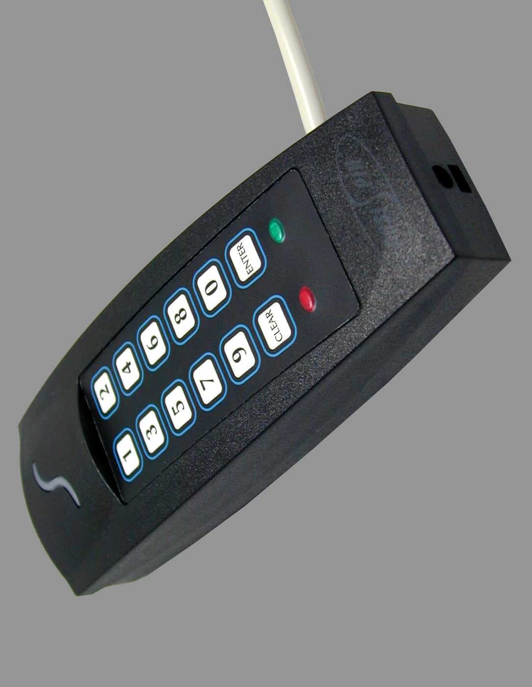
N4CPOSIPROXPOSI PROX GPS-880 SERIES PROXIMITY READER
Position Technology Inc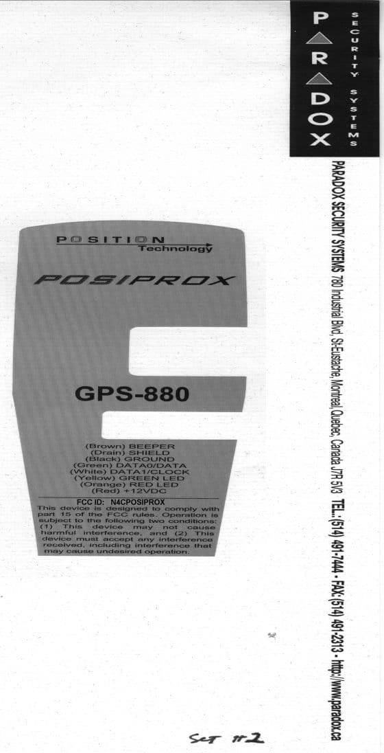
Click to zoom
Application Details
- Equipment Class
- DCD - Part 15 Low Power Transmitter Below 1705 kHz
- Date of Grant
- May 18, 1999
- Application Purpose
- Original Equipment
- Date of Application
- Aug 17, 1998
- Equipment Note
- POSI PROX GPS-880 SERIES PROXIMITY READER
- Frequency Range
- 0.12500000 - 0.12500000
- Company
- Position Technology Inc
- Country
- Canada
Documents & Files

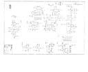
Document Text
Text extracted from the exhibit documents filed with the FCC. Open a document above to read the original.
External Photos
External View PCB Component Side Loop Coil PCB Trace Side
Test Report
KTL Ottawa Safety - EMI - Telecom - ISO Guide 25 Master: ktlPT15209 Date: August 5, 1998 ENGINEERING TEST REPORT ON: PARADOX SECURITY SYSTEMS "GPS 880 CARD READER" FCC ID: N4CPOSIPROX IN ACCORDANCE WITH: FCC PART 15, SUBPART C, PARAGRAPH 15.209 GENERAL LIMITS FOR LOW POWER TRANSMITTERS PROJECT NO.: 8R00488.2 TESTED FOR: PARADOX SECURITY SYSTEMS 780 INDUSTRIAL BLVD. STE EUSTACHE, QUEBEC J7R 5V3 TESTED BY: KTL OTTAWA INC. 3325 RIVER ROAD, R.R. 5 OTTAWA, ONTARIO K1V 1H2 NVLAP LAB CODE: 100351-0 JULY 1998 This document contains 18 pages including this one. KTL Ottawa Inc. authorizes the above named company to reproduce this report provided it is reproduced in its entirety and for use by the company’s employees only. Any use which a third party makes of this report, or any reliance on or decisions to be made based on it, are the responsibility of such third parties. KTL Ottawa Inc. accepts no responsibility for damages, if any, suffered by any third party as a result of decisions made or actions based on this report. This report applies only to the items tested. KTL Ottawa FCC PART 15, SUBPART C PARAGRAPH 15.209 PROJECT NO.: 8R00488.2 EQUIPMENT: GPS 880 Card Reader FCC ID: N4CPOSIPROX Page 2 of 16 Table Of Contents Section 1. Summary of Test Results General Summary of Test Data Section 2. General Equipment Specification Specifications Modifications Theory of Operation System Diagram Section 3. Powerline Conducted Emissions Test Results Graphs Photographs Section 4. Radiated Emissions Test Results Table Photographs Section 5. Test Equipment List Annex A. Test Diagrams Conducted Emissions Radiated Prescan Test Site for Radiated Emissions KTL Ottawa FCC PART 15, SUBPART C PARAGRAPH 15.209 PROJECT NO.: 8R00488.2 EQUIPMENT: GPS 880 Card Reader FCC ID: N4CPOSIPROX Page 3 of 16 Section 1.Summary Of Test Results Manufacturer:GPS 880 Model No.:Item #2 Serial No.:None General: All measurements are traceable to national standards. These tests were conducted on a sample of the equipment for the purpose of demonstrating compliance with FCC Part 15, Subpart C for low power devices. All tests were conducted using measurement procedure ANSI C63.4-1992. Radiated Emissions were made on an open area test site. New SubmissionProduction Unit Class II Permissive ChangePre-Production Unit THIS TEST REPORT RELATES ONLY TO THE ITEM(S) TESTED. THE FOLLOWING DEVIATIONS FROM, ADDITIONS TO, OR EXCLUSIONS FROM THE TEST SPECIFICATIONS HAVE BEEN MADE. See “ Summary of Test Data”. NVLAP LAB CODE: 100351-0 TESTED BY: ___________________________________ DATE: __________________ Tom Tidwell, Senior Technologist APPROVED BY: ________________________________ DATE: __________________ W. Waterhouse, RF Engineering Lab Manager KTL Ottawa FCC PART 15, SUBPART C PARAGRAPH 15.209 PROJECT NO.: 8R00488.2 EQUIPMENT: GPS 880 Card Reader FCC ID: N4CPOSIPROX Page 4 of 16 Summary Of Test Data NAME OF TESTPARA. NO.RESULT Powerline Conducted Emissions15.207Not Applicable Radiated Emissions15.209Complies Occupied BandwidthNot SpecifiedInformative Only Footnotes For N/A’s: The E.U.T. connects to a security alarm panel for power. Test Conditions: Temperature: 25 ° C Humidity:50 % KTL Ottawa FCC PART 15, SUBPART C PARAGRAPH 15.209 PROJECT NO.: 8R00488.2 EQUIPMENT: GPS 880 Card Reader FCC ID: N4CPOSIPROX Page 5 of 16 Section 2.General Equipment Specification Frequency Range: 0.125 MHz Operating Frequency(ies) of Sample: 0.1258 MHz Modulation: Pulse Modulated Emission Designator: 377HP0N Integral Antenna YesNo Note: If antenna is not integral to transmitter explain method of attachment and type of unique connector: KTL Ottawa FCC PART 15, SUBPART C PARAGRAPH 15.209 PROJECT NO.: 8R00488.2 EQUIPMENT: GPS 880 Card Reader FCC ID: N4CPOSIPROX Page 6 of 16 Description of Modification for Class II Permissive Change KTL Ottawa FCC PART 15, SUBPART C PARAGRAPH 15.209 PROJECT NO.: 8R00488.2 EQUIPMENT: GPS 880 Card Reader FCC ID: N4CPOSIPROX Page 7 of 16 Modifications Made During Testing KTL Ottawa FCC PART 15, SUBPART C PARAGRAPH 15.209 PROJECT NO.: 8R00488.2 EQUIPMENT: GPS 880 Card Reader FCC ID: N4CPOSIPROX Page 8 of 16 Theory of Operation The E.U.T. generates a pulsed carrier at 125 kHz continuously. When the ID card is placed within this field, the card is powered by the 125 kHz field and "wakes up" to transmit its unique ID number. If the ID number is valid it is decoded by the reader and sent to the host controller via data cables. The host controller provides 12.5 Vdc power to the reader. System Diagram Host Controller Posiprox Reader ID Card Reader RF Field Card ID Data Data To Controller KTL Ottawa FCC PART 15, SUBPART C PARAGRAPH 15.209 PROJECT NO.: 8R00488.2 EQUIPMENT: GPS 880 Card Reader FCC ID: N4CPOSIPROX Page 9 of 16 Section 3.Powerline Conducted Emissions NAME OF TEST: Powerline Conducted EmissionsPARA. NO.: 15.207 TESTED BY:DATE: Test Conditions: Standard Temperature and Humidity Standard Test Voltage Minimum Standard: FrequencyMaximum Powerline Conducted RF Voltage (MHz) ( μ μμ μ V)(dB μ μμ μ V) 0.45 - 30.025048 Test Results: Complies / Does not comply. See attached graph(s). Measurement Data: See attached graph(s). Method of Measurement:(Procedure ANSI C63.4-1992) Measurements were made using a spectrum analyzer with 10 kHz RBW, Peak Detector. Any emissions that are close to the limit are measured using a test receiver with 10 kHz bandwidth, CISPR Quasi-Peak Detector. KTL Ottawa FCC PART 15, SUBPART C PARAGRAPH 15.209 PROJECT NO.: 8R00488.2 EQUIPMENT: GPS 880 Card Reader FCC ID: N4CPOSIPROX Page 10 of 16 Powerline Conducted Photographs(Worst Case Configuration) SIDE VIEW FRONT VIEW KTL Ottawa FCC PART 15, SUBPART C PARAGRAPH 15.209 PROJECT NO.: 8R00488.2 EQUIPMENT: GPS 880 Card Reader FCC ID: N4CPOSIPROX Page 11 of 16 Section 4.Radiated Emissions NAME OF TEST: Radiated EmissionsPARA. NO.: 15.209 TESTED BY: Tom TidwellDATE: July 31, 1998 Minimum Standard: The field strength of emissions from the device shall not …
Text truncated - open the document above for the full version.
Contact Information
Applicant
Marc Bertrand(Certification Manager)
Technical Contact
Non-Technical Contact
KTL OTTAWAJOANNE A BACKES
[email protected]1-800-563-6336
Test Firm
Nemko Canada Inc.Stuart Beck
Technical Specifications
| # | Rule Parts | Frequency Range | Power Output | Emission |
|---|---|---|---|---|
| 1 | 15C | 0.125 MHz - 0.125 MHz | 0.00 µW | 377HP0N |
Other Applications from Position Technology Inc
N4CPOSIPIN
Jun 13, 2002FDS - Part 15 Field Disturbance Sensor
Equipment Class
FDS - Part 15 Field Disturbance Sensor