N6C-23BTBLE Module
Silex Technology, Inc.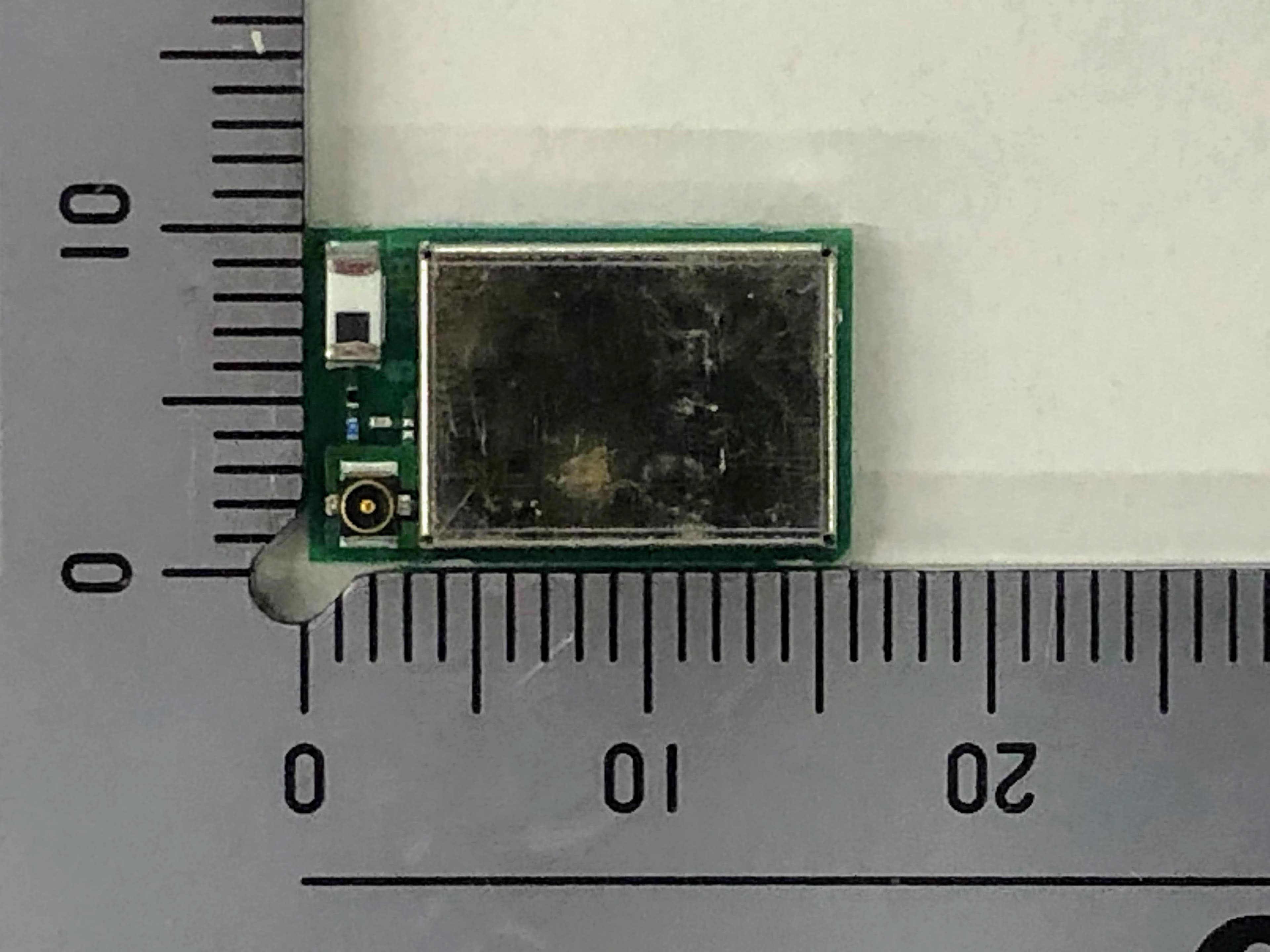
Click to zoom
Application Details
- Equipment Class
- DTS - Digital Transmission System
- Date of Grant
- Aug 19, 2020
- Application Purpose
- Original Equipment
- Date of Application
- Aug 19, 2020
- Equipment Note
- BLE Module
- Frequency Range
- 2402.00000000 - 2480.00000000
- Company
- Silex Technology, Inc.
- Country
- Japan
Documents & Files
Document Text
Text extracted from the exhibit documents filed with the FCC. Open a document above to read the original.
Users Manual
User Manual Since this module is not sold to general end users directly, there is no user manual of module. For the details about this module, please refer to the specification sheet of module. This module should be installed in the host device according to the interface specification (installation procedure). FCC Notice This device complies with Part 15 of FCC Rules. Operation is subject to the following two conditions: (1) this device may not cause harmful interference, and (2) this device must accept any interference received, including interference that may cause undesired operation. List of applicable FCC rules This device complies with below part 15 of the FCC Rules. Part 15 Subpart C Test Modes silex technology, Inc. uses various test mode programs for test set up which operate separate from production firmware. Host integrators should contact silex technology, Inc. for assistance with test modes needed for module/host compliance test requirements. Additional testing, Part 15 Subpart B disclaimer The modular transmitter is only FCC authorized for the specific rule parts (i.e., FCC transmitter rules) listed on the grant, and the host product manufacturer is responsible for compliance to any other FCC rules that apply to the host not covered by the modular transmitter grant of certification. The final host product still requires Part 15 Subpart B compliance testing with the modular transmitter installed. RF exposure considerations This equipment complies with FCC radiation exposure limits set forth for an uncontrolled environment and meets the FCC radio frequency (RF) Exposure Guidelines as this equipment has very low levels of RF energy. Co-Location Rule This transmitter must not be co-located or operated in conjunction with any other antenna or transmitter. Label and compliance information Following information must be indicated on the host device of this module. Contains Transmitter Module FCC ID:N6C-23BT Or Contains FCC ID:N6C-23BT FCC CAUTION The following statements must be described on the user manual of the host device of this module; FCC CAUTION Changes or modifications not expressly approved by the party responsible for compliance could void the userbs authority to operate the equipment. Antenna List Vender Model No. Antenna Type Antenna Gain [dBi] Unictron CW324S CHIP (On board) 1.6 Unictron H2B1PC1A1C (AA258) PCB 2.9 ISED Notice This device contains licence-exempt transmitter(s)/receiver(s) that comply with Innovation, Science and Economic Development Canada’s licence-exempt RSS(s). Operation is subject to the following two conditions: 1. This device may not cause interference. 2. This device must accept any interference, including interference that may cause undesired operation of the device. L’émetteur/récepteur exempt de licence contenu dans le présent appareil est conforme aux CNR d’Innovation, Sciences et Développement économique Canada applicables aux appareils radio exempts de licence. L’exploitation est autorisée aux deux conditions suivantes : 1. L’appareil ne doit pas produire de brouillage; 2. L’appareil doit accepter tout brouillage radioélectrique subi, même si le brouillage est susceptible d’en compromettre le fonctionnement. Label and compliance information The following information must be indicated on the host device of this module. Les informations suivantes doivent être indiquées sur le périphérique hôte de ce module. Contains Transmitter Module IC: 4908A-23BT Or Contains IC: 4908A-23BT RF exposure considerations This equipment complies with ISED radiation exposure limits set forth for an uncontrolled environment and meets RSS-102 of the ISED radio frequency (RF) Exposure rules as this equipment has very low levels of RF energy. Cet équipement est conforme aux limites d’exposition aux rayonnements énoncées pour un environnement non contrôlé et respecte les règles d’exposition aux fréquences radioélectriques (RF) CNR-102 de l’ISDE puisque cet appareil a une niveau tres bas d'energie RF. Antenna Type This radio transmitter (4908A-23BT) has been approved by Innovation, Science and Economic Development Canada to operate with the antenna types listed below, with the maximum permissible gain indicated. Antenna types not included in this list that have a gain greater than the maximum gain indicated for any type listed are strictly prohibited for use with this device. Antenna Type Gain Impedance CHIP Antenna (On Board) 1.6dBi 50ohms PCB Antenna 2.9dBi 50ohms Le présent émetteur radio (4908A-23BT) a été approuvé par Innovation, Sciences et Développement économique Canada pour fonctionner avec les types d'antenne énumérés ci-dessous et ayant un gain admissible maximal. Les types d'antenne non inclus dans cette liste, et dont le gain est supérieur au gain maximal indiqué pour tout type figurant sur la liste, sont strictement interdits pour l'exploitation de l'émetteur. Type d'antenne Gain Impedance Antenne CHIP (embarquée) 1.6dBi 50ohms Antenne PCB 2.9dBi 50ohms
Cover Letter(s)
1 KDB996369 Check List FCC ID: N6C-23BT Applicant: Silex Technology, Inc. This transmitter complies with KDB996369 D03 as indicated below: Modular approval requirement Applicable Not Applicable 2.2 List of applicable FCC rules List the FCC rules that are applicable to the modular transmitter. These are the rules that specifically establish the bands of operation, the power, spurious emissions, and operating fundamental frequencies. DO NOT list compliance to unintentional-radiator rules (Part 15 Subpart B) since that is not a condition of a module grant that is extended to a host manufacturer. See also Section 2.10 below concerning the need to notify host manufacturers that further testing is required. Please refer to User Manual 2.3 Summarize the specific operational use conditions Describe use conditions that are applicable to the modular transmitter, including for example any limits on antennas, etc. For example, if point-to -point antennas are used that require reduction in power or compensation for cable loss, then this information must be in the instructions. If the use condition limitations extend to professional users, then instructions must state that this information also extends to the host manufacturer’s instruction manual. In addition, certain information may also be needed, such as peak gain per frequency band and minimum gain, specifically for master devices in 5 GHz DFS bands. 2.4 Limited module procedures If a modular transmitter is approved as a “limited module,” then the modu le manufacturer is responsible for approving the host environment that the limited module is used with. The manufacturer of a limited module must describe, both in the filing and in the installation instructions, the alternative means that the limited module manufacturer uses to verify that the host meets the necessary requirements to satisfy the module limiting conditions. A limited module manufacturer has the flexibility to define its alternative method to address the conditions that limit the initial app roval, such as: shielding, minimum signaling amplitude, buffered modulation/data inputs, or power supply regulation. The alternative method could include that the limited module manufacturer reviews detailed test data or host designs prior to giving the host manufacturer approval. This limited module procedure is also applicable for RF exposure evaluation when it is necessary to demonstrate compliance in a specific host. The module manufacturer must state how control of the product into which the modular transmitter will be installed will be maintained such that full compliance of the product is always ensured. For additional hosts other than the specific host originally granted with a limited module, a Class II permissive change is required on the module grant to register the additional host as a specific host also approved with the module. 2 2.5 Trace antenna designs For a modular transmitter with trace antenna designs, see the guidance in Question 11 of KDB Publication 996369 D02 FAQ – Modules for Micro-Strip Antennas and traces. The integration information shall include for the TCB review the integration instructions for the following aspects: layout of trace design, parts list (BOM), antenna, connectors, and isolation requirements. a) Information that includes permitted variances (e.g., trace boundary limits, thickness, length, width, shape(s), dielectric constant, and impedance as applicable for each type of antenna); b) Each design shall be considered a different type (e.g., antenna length in multiple(s) of frequency, the wavelength, and antenna shape (traces in phase) can affect antenna gain and must be considered); c) The parameters shall be provided in a manner permitting host manufacturers to design the printed circuit (PC) board layout; d) Appropriate parts by manufacturer and specifications; e) Test procedures for design verification; and f) Production test procedures for ensuring compliance. The module grantee shall provide a notice that any deviation(s) from the defined parameters of the antenna trace, as described by the instructions, require that the host product manufacturer must notify the module grantee that they wish to change the antenna trace design. In this case, a Class II permissive change application is required to be filed by the grantee, or the host manufacturer can take responsibility through the change in FCC ID (new application) procedure followed by a Class II permissive change application. 2.6 RF exposure considerations It is essential for module grantees to clearly and explicitly state the RF exposure conditions that permit a host product manufacturer to use the module. Two types of instructions are required for RF exposure information: (1) to the host product manufacturer, to define the application conditions (mobile, portable – xx cm from a person’s body); and (2) additional text needed for the host product manufacturer to provide to end users in their end-product manuals. If RF exposure statements and use conditions are not provided, then the host product manufacturer is required to take responsibility of the module through a change in FCC ID (new application). Please refer to User Manual 2.7 Antennas A list of antennas included in the application for certification must be provided in the instructions. For modular transmitters approved as limited modules, all applicable professio nal installer instructions must be included as part of the information to the host product manufacturer. The antenna list shall also identify the antenna types (monopole, PIFA, dipole, etc. (note that for example an “omni-directional antenna” is not considered to be a specific “antenna type”)). For situations where the host product manufacturer is responsible for an external connector, for example with an RF pin and antenna trace design, the integration instructions shall inform the installer that unique an tenna connector must be used on the Part 15 authorized transmitters used in …
Text truncated - open the document above for the full version.
ID Label/Location Info
Drawing No.:JW206000XX draft5 © silex technology, Inc. Date:July 21, 2020 (15/22) CONFIDENTIAL 8. マーキング仕様 / Marking specifications FCC ID 2D Code Format:Data Matrix (Serial number) IC ID MIC Mark and number Serial number 原産国 Country of origin 製造者名 Manufacturer name モデル名 Model name
RF Exposure Info
UL Japan, Inc. Ise EMC Lab 4383-326 Asama-cho, Ise-shi, Mie 516-0021 Japan T:: +81.596.24.8999 / F:: +81.596.24.8124 / W:: ul.com/jp July 20, 2020 FCC ID: N6C-23BT To whom it may concern, We, UL Japan, Inc, hereby declare that BLE Module, model: SX-23BT (FCC ID: N6C-23BT) of silex technology, Inc. is exempt from RF exposure SAR evaluation as its output power meets the exclusion limits stated in KDB 447498D01(v06). KDB 447498D01(v06) has the following exclusion for portable devices: The 1g and 10g SAR test exclusion thresholds for 100 MHz to 6 GHz at test separation distances ≤ 50 mm are determined by: [(max. power of channel, including tune-up tolerance, mW)/(min. test separation distance, mm)] ꞏ[√f(GHz)] ≤ 3.0 for 1-g SAR and ≤ 7.5 for 10-g extremity SAR, where •f(GHz) is the RF channel transmit frequency in GHz •Power and distance are rounded to the nearest mW and mm before calculation •The result is rounded to one decimal place for comparison The test exclusions are applicable only when the minimum test separation distance is ≤ 50 mm and for transmission frequencies between 100 MHz and 6 GHz. When the minimum test separation distance is < 5 mm, a distance of 5 mm is applied to determine SAR test exclusion. This device has f = 2.48 GHz and distance = 5 mm (minimum separation distance: 5 mm was used in the calculation) and the maximum average output power was 1 mW So for this device: 1 mW[maximum average output power]/5 mm[minimum separation distance]*√2.48 = 0.3 *This is less than 3.0, so no SAR is required. Even taking into account the tolerance, this device can be satisfied with the limits. Thank you for your attention to this matter. Satofumi Matsuyama Engineer of Ise EMC Lab. Consumer Technology Division UL Japan, Inc.
Test Report
Test report No. : 13292801H-A-R2 Page: 1 of 67 Issued date : August 19, 2020 F CC ID : N6C-23BT UL Japan, Inc. Ise EMC Lab. 4383-326 Asama-cho, Ise-shi, Mie-ken 516-0021 JAPAN Telephone : +81 596 24 8999 Facsimile : +81 596 24 8124 Report Cover Page - 13-EM-F0429 Issue # 17.0 RADIO TEST REPORT Test Report No. : 13292801H-A-R2 Applicant : silex technology, Inc. Type of EUT : BLE Module Model Number of EUT : SX-23BT FCC ID : N6C-23BT Test regulation : FCC Part 15 Subpart C: 2020 Test Result : Complied (Refer to SECTION 3.2) Da te of test: June 9 to 17, 2020 Representative test engineer: Yuta Moriya Engineer Consumer Technology Division Appr oved by: Satofumi Matsuyama Engineer Consumer Technology Division This report contains data that are not covered by the NVLAP accreditation. There is no testing item of "Non-accreditation". 1. This test report shall not be reproduced in full or partial, without the written approval of UL Japan, Inc. 2. The results in this report apply only to the sa mple tested. 3. This sample t ested is in compliance with the limits of the above regulation. 4. The test results in this tes t report are traceable to the national or international standards. 5. This test report covers Radio technical require ments. It does not cover administrative issues such as Manual or non-Radio test related Requirement s. (if applicable) 6. The all test items in this test report are conducted by UL Japan, Inc. Ise EMC Lab. 7. This test repo rt must not be used by the customer to claim product certificati on, approval, or endorsement by NVLAP, NIST, or any agency of the U.S. Government. 8. The informat ion provided from the customer for this report is identified in Section 1. 9. This report is a revised versi on of 13292801H-A-R1. 13292801H-A-R1 is replaced with this report. This laboratory is accredited by the NVLAP LAB CODE 200572-0, U.S.A. The tests reported herein have been performed in accordance with its terms of accreditation. *As for the range of Accreditation in NVLAP, you may refer to the WEB address, http://japan.ul.com/resources/emc_accredited/ Test report No. : 13292801H-A-R2 Page: 2 of 67 Issued date: August 19, 2020 F CC ID : N6C-23BT UL Japan, Inc. Ise EMC Lab. 4383-326 Asama-cho, Ise-shi, Mie-ken 516-0021 JAPAN Telephone : +81 596 24 8999 Facsimile : +81 596 24 8124 REVISION HISTORY Original Test Report No.: 13292801H-A Revision Test report No. Date Page revised Contents - ( Original) 13292801H-A July 16, 2020 - - 1 13292801H-A-R1 July 27, 2020 P 1 P 9 Change of A2LA logo to NVLAP. Change of A2LA Certificate Number to NVLAP Lab. Code. 1 13292801H-A-R1 July 27, 2020 P 5 Correction of Antenna Gain of Chip Antenna in SECTION 2.2 1.5 dBi→1.6 dBi 1 13292801H-A-R1 July 27, 2020 P 5 Correction of Receipt Date in SECTION 2.1 June 11, 2020→June 9, 2020 1 13292801H-A-R1 July 27, 2020 P 29 Deletion of below note in APPENDIX 1: Test data (Average Output Power) The average output power was measured with the lowest order modulation and lowest data rate configuration in each IEEE 802.11 mode based on KDB 248227 D01. 213292801H-A-R2 August 19, 2020 P 1 Correction of Date of test June 9 to July 13, 2020→ Jun e 9 to 17, 2020 213292801H-A-R2 August 19, 2020 P 5 Correction of Maximum clock frequency in SECTION 2.2 2480 MHz→32 MHz 213292801H-A-R2 August 19, 2020 P 10 Deletion of 0 dBm (Maximum Peak Output Power only) in SECTION 4.1 Addition of explanator y note *1) 213292801H-A-R2 August 19, 2020 P 27 to 29 Deletion of 0 dBm power setting data in APPENDIX 1: Test data (Maximum Peak Output Powe r and Average Output Power) Test report No. : 13292801H-A-R2 Page: 3 of 67 Issued date: August 19, 2020 F CC ID : N6C-23BT UL Japan, Inc. Ise EMC Lab. 4383-326 Asama-cho, Ise-shi, Mie-ken 516-0021 JAPAN Telephone : +81 596 24 8999 Facsimile : +81 596 24 8124 Reference: Abbreviations (Including words undescribed in this report) A2LA The American Association for Laboratory Accreditation MCS Modulation and Coding Scheme AC Alternating Current MRA Mutual Recognition Arrangement AFH Adaptive Frequency Hopping N/A Not Applicable AM Amplitude Modulation NIST National Institute of Standards and Technology Amp, AMP Amplifier NS No signal detect. ANSI American National Standards Institute NSA Normalized Site Attenuation Ant, ANT Antenna NVLAP National Voluntary Laboratory Accreditation Program AP Access Point OBW Occupied Band Width ASK Amplitude Shift Keying OFDM Orthogonal Frequency Division Multiplexing Atten., ATT Attenuator P/M Power meter AV Average PCB Printed Circuit Board BPSK Binary Phase-Shift Keying PER Packet Error Rate BR Bluetooth Basic Rate PHY Physical Layer BTBl uetoo thPKPeak BT LE Bluetooth Low Energy PN Pseudo random Noise BWBand Wid thPRBS Pseudo-Random Bit Sequen ce Cal Int Calibration Interval PSD Power Spectral Density CCK Complementary Code Keying QAM Quadrature Amplitude Modulation Ch., CH Channel QP Quasi-Peak CISPR Comite International Special des Perturbations Radioelectriques QPSK Quadri-Phase Shift Keying CW Continuous Wave RBW Resolution Band Width DBPSK Differential BPSK RDS Radio Data System DC Dir ect Current RERadi o Equipmen t D-fac tor Distance factor RF Radio Frequency DFS Dynamic Frequency Selection RMS Root Mean Square DQPSKDif ferential QPSKRSS Radio Standards Specifications DSSS Direct Sequence Spread Spectrum Rx Receiving EDR Enhanced Data Rate SA, S/A Spectrum Analyzer EIRP, e.i.r.p. Equivalent Isotropically Radiated Power SG Signal Generator EM CE lectroMagnetic Compatibili ty SVSWR Site-Voltage Standing Wave Ratio EMI ElectroM agnetic Interference TR Te st Receiver EN Eu ropean NormTxTransmitting ERP, e.r.p. Effective Radiated Power VBW Video BandWidth EU Eu ropean UnionVert.Vertical EUT Equipment Under Test WLAN Wireless LAN Fac.Factor FCC Federal Communications Commission FHSS Frequency Hopping Spread Spectrum FMFrequ ency Modulati on Freq.Freque nc y FSK Frequency Shift Keying GF SKG aussian Frequency-Shift Key ing GN SS Global Navigation Satellite System GPS G…
Text truncated - open the document above for the full version.
Test Setup Photos
Test report No. : 13292801H-A-R2 Page : 62 of 67 Issued date : August 19, 2020 FCC ID : N6C-23BT UL Japan, Inc. Ise EMC Lab. 4383-326 Asama-cho, Ise-shi, Mie-ken 516-0021 JAPAN Telephone : +81 596 24 8999 Facsimile : +81 596 24 8124 APPENDIX 3: Photographs of test setup Conducted Emission Chip Antenna Photo 1 Photo 2 Test report No. : 13292801H-A-R2 Page : 63 of 67 Issued date : August 19, 2020 FCC ID : N6C-23BT UL Japan, Inc. Ise EMC Lab. 4383-326 Asama-cho, Ise-shi, Mie-ken 516-0021 JAPAN Telephone : +81 596 24 8999 Facsimile : +81 596 24 8124 Conducted Emission PCB Antenna Photo 1 Photo 2 Test report No. : 13292801H-A-R2 Page : 64 of 67 Issued date : August 19, 2020 FCC ID : N6C-23BT UL Japan, Inc. Ise EMC Lab. 4383-326 Asama-cho, Ise-shi, Mie-ken 516-0021 JAPAN Telephone : +81 596 24 8999 Facsimile : +81 596 24 8124 Radiated Spurious Emission Chip Antenna Photo 1 Photo 2 Test report No. : 13292801H-A-R2 Page : 65 of 67 Issued date : August 19, 2020 FCC ID : N6C-23BT UL Japan, Inc. Ise EMC Lab. 4383-326 Asama-cho, Ise-shi, Mie-ken 516-0021 JAPAN Telephone : +81 596 24 8999 Facsimile : +81 596 24 8124 Radiated Spurious Emission PCB Antenna Photo 1 Photo 2 Test report No. : 13292801H-A-R2 Page : 66 of 67 Issued date : August 19, 2020 FCC ID : N6C-23BT UL Japan, Inc. Ise EMC Lab. 4383-326 Asama-cho, Ise-shi, Mie-ken 516-0021 JAPAN Telephone : +81 596 24 8999 Facsimile : +81 596 24 8124 Worst Case Position Chip Antenna Below 1 GHz: (Horizontal: X-axis/ Vertical:X-axis) Above 1 GHz: (Horizontal: X-axis/ Vertical:X-axis) X-axis Y-axis Z-axis Test report No. : 13292801H-A-R2 Page : 67 of 67 Issued date : August 19, 2020 FCC ID : N6C-23BT UL Japan, Inc. Ise EMC Lab. 4383-326 Asama-cho, Ise-shi, Mie-ken 516-0021 JAPAN Telephone : +81 596 24 8999 Facsimile : +81 596 24 8124 Worst Case Position PCB Antenna Module Below 1 GHz: (Horizontal: X-axis/ Vertical:X-axis) Above 1 GHz: (Horizontal: X-axis/ Vertical:Y-axis) Antenna Below 1 GHz: (Horizontal: X-axis/ Vertical:X-axis) Above 1 GHz: (Horizontal: X-axis/ Vertical:Y-axis) Module Antenna X-axis X-axis Y-axis Y-axis Z-axis Z-axis End of Report
Contact Information
Applicant
Yoshinori Nakai(General Manager)
Technical Contact
UL Japan, Inc.Satofumi Matsuyama
[email protected]81-596-24-8999
4383-326 Asama-cho, Ise-shi · Mie-ken · Japan
Test Firm
UL Japan, Inc.Masamichi Ishii
Technical Specifications
| # | Rule Parts | Frequency Range | Power Output |
|---|---|---|---|
| 1 | 15C | 2.40 GHz - 2.48 GHz | 1.40 mW |
Other Applications from Silex Technology, Inc.
N6C-SDMAX6E
Mar 26, 2026SX-SDMAX6E
Equipment Class
DTS - Digital Transmission System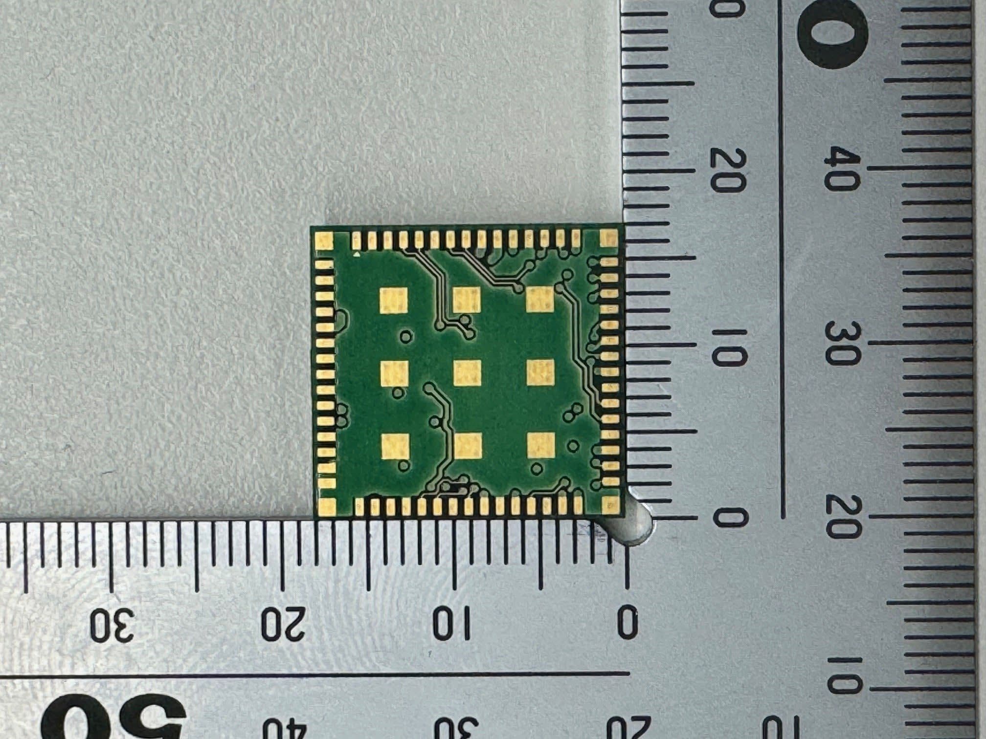
N6C-SDMAH
Feb 04, 2024Embedded Wireless Module
Equipment Class
DTS - Digital Transmission System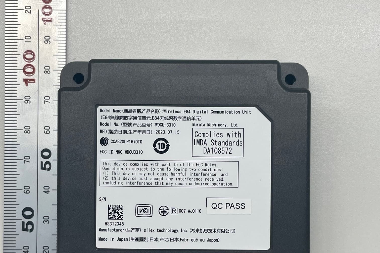
N6C-WDCU3310H
Oct 08, 2023Wireless E84 Digital Communication Unit
Equipment Class
NII - Unlicensed National Information Infrastructure TX
N6C-AP200AC
May 31, 2021Wireless LAN Access Point
Equipment Class
DTS - Digital Transmission System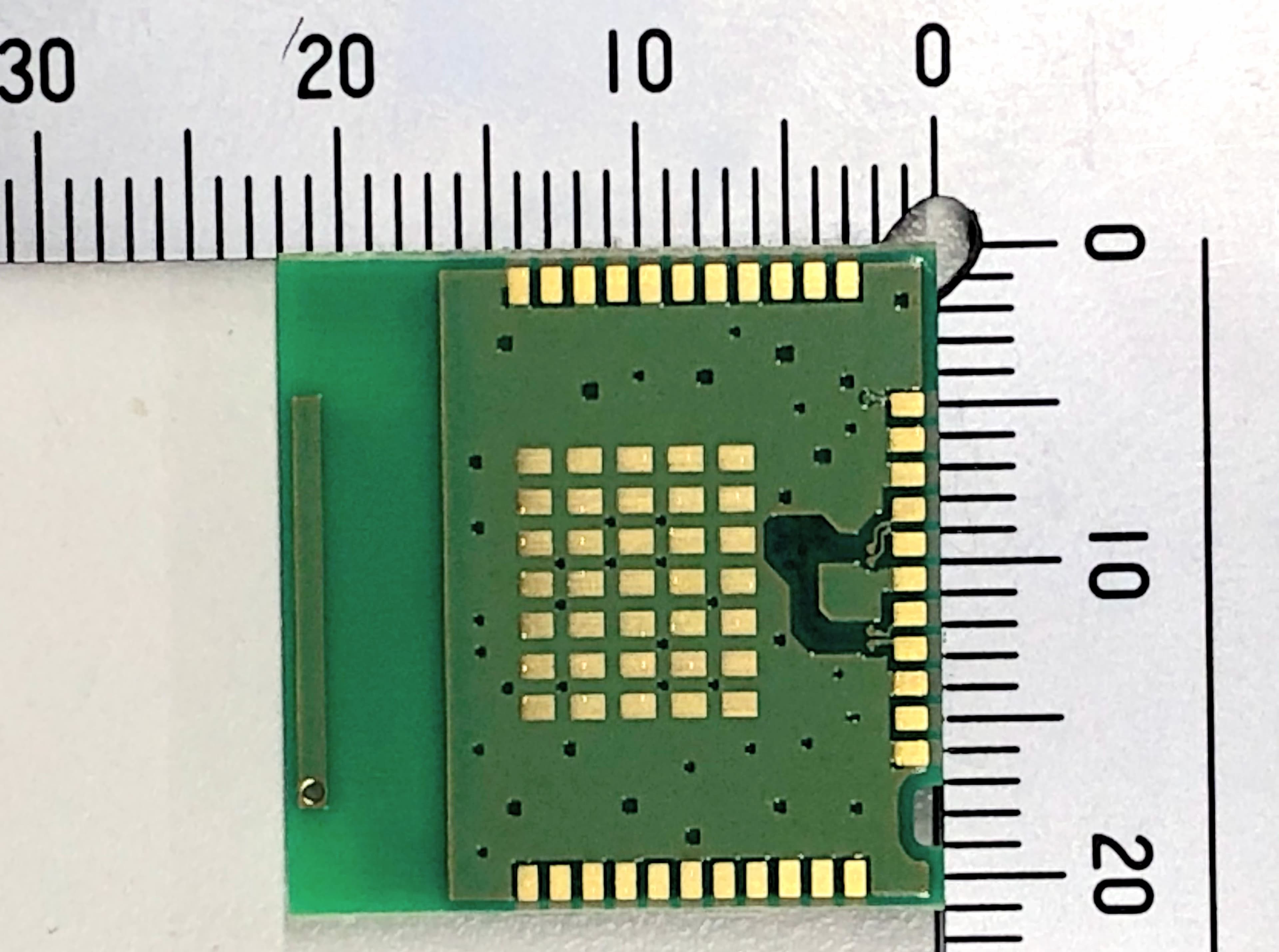
N6C-USBAC
Apr 19, 2021Embedded Wireless Module
Equipment Class
DTS - Digital Transmission System