N6C-SDMANSDIO Wireless Module
Silex Technology, Inc.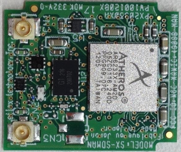
Click to zoom
Application Details
- Equipment Class
- DSS - Part 15 Spread Spectrum Transmitter
- Date of Grant
- Aug 19, 2012
- Application Purpose
- Original Equipment
- Date of Application
- Aug 19, 2012
- Equipment Note
- SDIO Wireless Module
- Frequency Range
- 2402.00000000 - 2480.00000000
- Company
- Silex Technology, Inc.
- Country
- Japan
Documents & Files
Document Text
Text extracted from the exhibit documents filed with the FCC. Open a document above to read the original.
Users Manual
User’s manual Product: SDIO Wireless Module Model: SX-SDMAN For OEM integration only – device cannot be sold to general public. Therefore we will not supply the User’s manual, the installation manual is the official for OEM. FCC ID: N6C-SDMAN IC: 4908B-SDMAN We will ask OEM to include the following Notices required by FCC/ IC on the product and in the User’s manual. Drawing No.:XX Date:July 30, 2012 (18/19) CONFIDENTIAL © silex technology, Inc. 7. Notifications FCC ID:N6C-SDMAN IC :4908B-SDMAN NOTICE Federal Communication Interference Statement (United States only) This equipment has been tested and found to comply with the limits for a class B digital device, pursuant to Part 15 of the FCC rules. These limits are designed to provide reasonable protection against harmful interference in a residential installation. This equipment generates, uses, and can radiate radio frequency energy and, if not installed and used in accordance with the instructions, may cause harmful interference to radio communications. However, there is no guarantee that interference will not occur in a particular installation. If this equipment does cause harmful interference to radio or television reception, which can be determined by turning the equipment off and on, the user is encouraged to try to correct the interference by one or more of the following measures: • Re-orient or relocate the receiving antenna • Increase the separation between the equipment and receiver • Connect the equipment to an outlet on a circuit different from that to which the receiver is connected • Consult the dealer or an experienced radio/TV technician for help This device and its antenna(s) must not be co-located or operation in conjunction with any other antenna or transmitter. Canadian Depertment of Communications Industry Canada Notice (Canada only) This Class B digital apparatus complies with Canadian ICES-003. Cet appareil numérique de la classe B est conforme à la norme NMB-003 du Canada. FCC Rules, Part 15./ Industry Canadian This device complies with Part 15 of FCC Rules and Industry Canada licence-exempt RSS standard(s). Operation is subject to the following two conditions: • This device may not cause harmful interference, and • This device must accept any interference, including interference that may cause undesired operation of this device. Le présent appareil est conforme aux la partie 15 des règles de la FCC et CNR d'Industrie Canada applicables aux appareils radio exempts de licence. L'exploitation est autorisée aux deux conditions suivantes : • l'appareil ne doit pas produire de brouillage, et • l'utilisateur de l'appareil doit accepter tout brouillage radioélectrique subi, même si le brouillage est susceptible d'en compromettre le fonctionnement. Drawing No.:XX Date:July 30, 2012 (19/19) CONFIDENTIAL © silex technology, Inc. This equipment complies with FCC/IC radiation exposure limits set forth for an uncontrolled environment and meets the FCC radio frequency (RF) Exposure Guidelines in Supplement C to OET65 and RSS-102 of the IC radio frequency (RF) Exposure rules. This equipment should be installed and operated keeping the radiator at least 20cm or more away from person’s body (excluding extremities: hands, wrists, feet and ankles). Cet équipement est conforme aux limites d’exposition aux rayonnements énoncées pour un environnement non contrôlé et respecte les règles les radioélectriques (RF) de la FCC lignes directrices d'exposition dans le Supplément C à OET65 et d’exposition aux fréquences radioélectriques (RF) CNR-102 de l’IC. Cet équipement doit être installé et utilisé en gardant une distance de 20 cm ou plus entre le dispositif rayonnant et le corps (à l’exception des extrémités : mains, poignets, pieds et chevilles). Under Industry Canada regulations, this radio transmitter may only operate using an antenna of a type and maximum (or lesser) gain approved for the transmitter by Industry Canada. To reduce potential radio interference to other users, the antenna type and its gain should be so chosen that the equivalent isotropically radiated power (e.i.r.p.) is not more than that necessary for successful communication. Conformément à la réglementation d'Industrie Canada, le présent émetteur radio peut fonctionner avec une antenne d'un type et d'un gain maximal (ou inférieur) approuvé pour l'émetteur par Industrie Canada. Dans le but de réduire les risques de brouillage radioélectrique à l'intention des autres utilisateurs, il faut choisir le type d'antenne et son gain de sorte que la puissance isotrope rayonnée équivalente (p.i.r.e.) ne dépasse pas l'intensité nécessaire à l'établissement d'une communication satisfaisante. This radio transmitter 4908B-SDMAN has been approved by Industry Canada to operate with the antenna types listed below with the maximum permissible gain and required antenna impedance for each antenna type indicated. Antenna types not included in this list, having a gain greater than the maximum gain indicated for that type, are strictly prohibited for use with this device. Le présent émetteur radio 4908B-SDMAN a été approuvé par Industrie Canada pour fonctionner avec les types d'antenne énumérés ci-dessous et ayant un gain admissible maximal et l'impédance requise pour chaque type d'antenne. Les types d'antenne non inclus dans cette liste, ou dont le gain est supérieur au gain maximal indiqué, sont strictement interdits pour l'exploitation de l'émetteur. For product available in the USA/Canada market, only channel 1~11 can be operated. Selection of other channels is not possible. This device is going to be operated in 5.15~5.25GHz frequency range, it is restricted in indoor environment only. Antenna information: Sleeve Antenna: 1.5dBi (2.4GHz), 2.1dBi (5GHz) Embedded Antenna: 2.5dBi (2.4GHz), 3.5dBi (5GHz) Frequency Tolerance:+/-20ppm WARNING: The FCC / The Industry Canada regulations provide that changes or modifications not expressly approved by the party responsible for compliance could vo…
Text truncated - open the document above for the full version.
Internal Photos
Antenna Sleeve Antenna Embedded Antenna
RF Exposure Info
UL Japan, Inc. Head Office EMC Lab. 4383-326 Asama-cho, Ise-shi, Mie-ken 516-0021 JAPAN Telephone : +81 596 24 8116 Facsimile : +81 596 24 8124 Applicant: silex technology, Inc. T ype of Equipment : Model No. : SX-SDMAN FCC ID: N6C-SDMAN IC Number:4908B-SDMAN silex technology, Inc. declares that Model : SX-SDMAN complies with FCC radiation exposure requirement specified in the FCC Rules 2.1091 (for mobile). RF Exposure Calculations: The following information provides the minimum separation distance for the highest gain antenna provided with the “SX-SDMAN“ as calculate d from FCC OET Bulletin 65 Appendix A, Table (B) Limits for General Population / Uncontrolled Exposure. This calculation is based on the highest EIRP possible from the system, considering maximum power and antenna gain, and considering a 1.0mW/cm^2 uncontrolled exposure limit. The Friis formula used was: S = (P * G) / (4* π * r 2 ) Where P = 13.93 mW (Maximum peak output power) G = 1.58 Numerical Antenna gain; equal to2.00dBi r =20.0 cm For: SX-SDMANS =0.00439 mW/cm 2 No. : 32IE0154-HO-01 RF Exposure / MPE Calculation SDIO Wireless Module (Bluetooth)
Test Report
Test report No. : 32IE0154-HO-01-B-R1 Page : 2 of 56 Issued date : July 25, 2012 Revised date : August 6, 2012 FCC ID : N6C-SDMAN UL Japan, Inc. Head Office EMC Lab. 4383-326 Asama-cho, Ise-shi, Mie-ken 516-0021 JAPAN Telephone : +81 596 24 8116 Facsimile : +81 596 24 8124 CONTENTS PAGE SECTION 1: Customer information ......................................................................................................... 3 SECTION 2: Equipment under test (E.U.T.) ........................................................................................... 3 SECTION 3: Test specification, procedures & results ............................................................................ 5 SECTION 4: Operation of E.U.T. during testing .................................................................................... 9 SECTION 5: Conducted Emission .......................................................................................................... 11 SECTION 6: Radiated Spurious Emission ............................................................................................ 12 SECTION 7: Antenna Terminal Conducted Tests ................................................................................ 13 APPENDIX 1: Data of EMI test .............................................................................................................. 14 Conducted Emission ......................................................................................................................... 14 20dB Bandwidth and Carrier Frequency Separation ......................................................................... 18 Number of Hopping Frequency ........................................................................................................ 21 Dwell time ......................................................................................................................................... 23 Maximum Peak Output Power .......................................................................................................... 26 Radiated Spurious Emission ............................................................................................................. 27 Conducted Spurious Emission .......................................................................................................... 36 Conducted Emission Band Edge compliance ................................................................................... 48 99%Occupied Bandwidth ................................................................................................................. 50 APPENDIX 2: Test instruments ............................................................................................................. 52 APPENDIX 3: Photographs of test setup ............................................................................................... 54 Conducted Emission ......................................................................................................................... 54 Radiated Spurious Emission ............................................................................................................. 55 Worst Case Position .......................................................................................................................... 56 Test report No. : 32IE0154-HO-01-B-R1 Page : 3 of 56 Issued date : July 25, 2012 Revised date : August 6, 2012 FCC ID : N6C-SDMAN UL Japan, Inc. Head Office EMC Lab. 4383-326 Asama-cho, Ise-shi, Mie-ken 516-0021 JAPAN Telephone : +81 596 24 8116 Facsimile : +81 596 24 8124 SECTION 1: Customer information Company Name : silex technology, Inc. Address : 2-3-1 Hikaridai, Seika-cho, Kyoto 619-0237, Japan Telephone Number : +81-774-98-3878 Facsimile Number : +81-774-98-3758 Contact Person : Toshiro Kometani SECTION 2: Equipment under test (E.U.T.) 2.1 Identification of E.U.T. Type of Equipment : SDIO Wireless Module Model No. : SX-SDMAN Serial No. : Refer to Section 4, Clause 4.2 Rating : DC3.3V Receipt Date of Sample : April 11, 2012 Country of Mass-production : Japan Condition of EUT : Production prototype (Not for Sale: This sample is equivalent to mass-produced items.) Modification of EUT : No Modification by the test lab Test report No. : 32IE0154-HO-01-B-R1 Page : 4 of 56 Issued date : July 25, 2012 Revised date : August 6, 2012 FCC ID : N6C-SDMAN UL Japan, Inc. Head Office EMC Lab. 4383-326 Asama-cho, Ise-shi, Mie-ken 516-0021 JAPAN Telephone : +81 596 24 8116 Facsimile : +81 596 24 8124 2.2 Product Description Model No: SX-SDMAN (referred to as the EUT in this report) is the SDIO Wireless Module. General Specification Clock frequency(ies) in the system : 26MHz Radio Specification Radio Type : Transceiver Method of Frequency Generation : Synthesizer Power Supply (inner) : DC1.2V Specification of Wireless LAN (IEEE802.11b/g/a/n-20/n-40) Type of radio IEEE802.11b IEEE802.11g IEEE802.11a IEEE802.11n (20 M band) IEEE802.11n (40 M band) Frequency of operation 2412-2462MHz 2412-2462MHz 5180-5320MHz *1) 5745-5825MHz 2412 - 2462MHz 5180-5320MHz *1) 5745-5825MHz 5190 - 5310MHz *2) 5755 - 5795MHz Type of modulation DSSS (CCK, DQPSK, DBPSK) OFDM-CCK (64QAM, 16QAM, QPSK, BPSK) OFDM (64QAM, 16QAM, QPSK, BPSK) Channel spacing 5MHz 20MHz 2.4GHz band 5MHz 5GHz band 20MHz 40MHz Antenna type Sleeve antenna: Sansei Embedded antenna: Ethertronics Antenna Gain Sleeve antenna: 1.0dBi (2.4GHz including cableloss 0.5dB), 1.1dBi (5GHz including cableloss 1.0dB) Embedded antenna: 2.0dBi (2.4GHz including cableloss 0.5dB), 2.5dBi (5GHz including cableloss 1.0dB) Antenna Connector type U.FL connector *1) 5180 - 5320MHz is applied for other test report.(Test Report No.: 32IE0154-HO-01-C) *2) 5190 - 5310MHz is applied for other test report.(Test Report No.: 32IE0154-HO-01-C) Specification of Bluetooth (Ver.4.0 + EDR) Type of radio Bluetooth Frequency of Operation 2402-2480MHz Type of Modulation FHSS Channel spacing 1MHz Antenna type Embedded antenna: Ethertronic…
Text truncated - open the document above for the full version.
Test Setup Photos
Test report No. : 32IE0154-HO-01-B-R1 Page : 54 of 56 Issued date : July 25, 2012 Revised date : August 6, 2012 FCC ID : N6C-SDMAN UL Japan, Inc. Head Office EMC Lab. 4383-326 Asama-cho, Ise-shi, Mie-ken 516-0021 JAPAN Telephone : +81 596 24 8116 Facsimile : +81 596 24 8124 APPENDIX 3: Photographs of test setup Conducted Emission Photo 1 Photo 2 Test report No. : 32IE0154-HO-01-B-R1 Page : 55 of 56 Issued date : July 25, 2012 Revised date : August 6, 2012 FCC ID : N6C-SDMAN UL Japan, Inc. Head Office EMC Lab. 4383-326 Asama-cho, Ise-shi, Mie-ken 516-0021 JAPAN Telephone : +81 596 24 8116 Facsimile : +81 596 24 8124 Radiated Spurious Emission Photo 1 Photo 2 Test report No. : 32IE0154-HO-01-B-R1 Page : 56 of 56 Issued date : July 25, 2012 Revised date : August 6, 2012 FCC ID : N6C-SDMAN UL Japan, Inc. Head Office EMC Lab. 4383-326 Asama-cho, Ise-shi, Mie-ken 516-0021 JAPAN Telephone : +81 596 24 8116 Facsimile : +81 596 24 8124 Worst Case Position (Horizontal: Module X-axis, Antenna X-axis/ Vertical:Module X-axis, Antenna Y-axis) Module Antenna X-axis X-axis Y-axis Y-axis Z-axis Z-axis End of Report
Contact Information
Applicant
Yoshinori Nakai(General Manager)
Technical Contact
UL Japan, Inc.Takahiro Hatakeda
[email protected]81-596-24-8116
4383-326 Asama-cho, Ise-shi · Mie-ken · Japan
Test Firm
UL Japan, Inc. Head office EMC Lab.Tetsuya Hashimoto
Technical Specifications
| # | Rule Parts | Frequency Range | Power Output |
|---|---|---|---|
| 1 | 15C | 2.40 GHz - 2.48 GHz | 13.90 mW |
Other Applications from Silex Technology, Inc.
N6C-SDMAX6E
Mar 26, 2026SX-SDMAX6E
Equipment Class
DTS - Digital Transmission System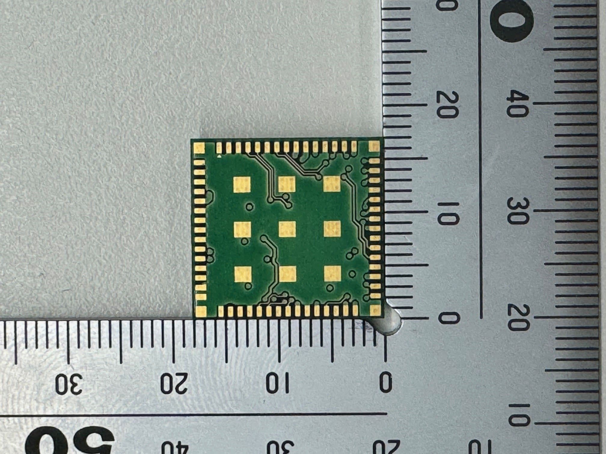
N6C-SDMAH
Feb 04, 2024Embedded Wireless Module
Equipment Class
DTS - Digital Transmission System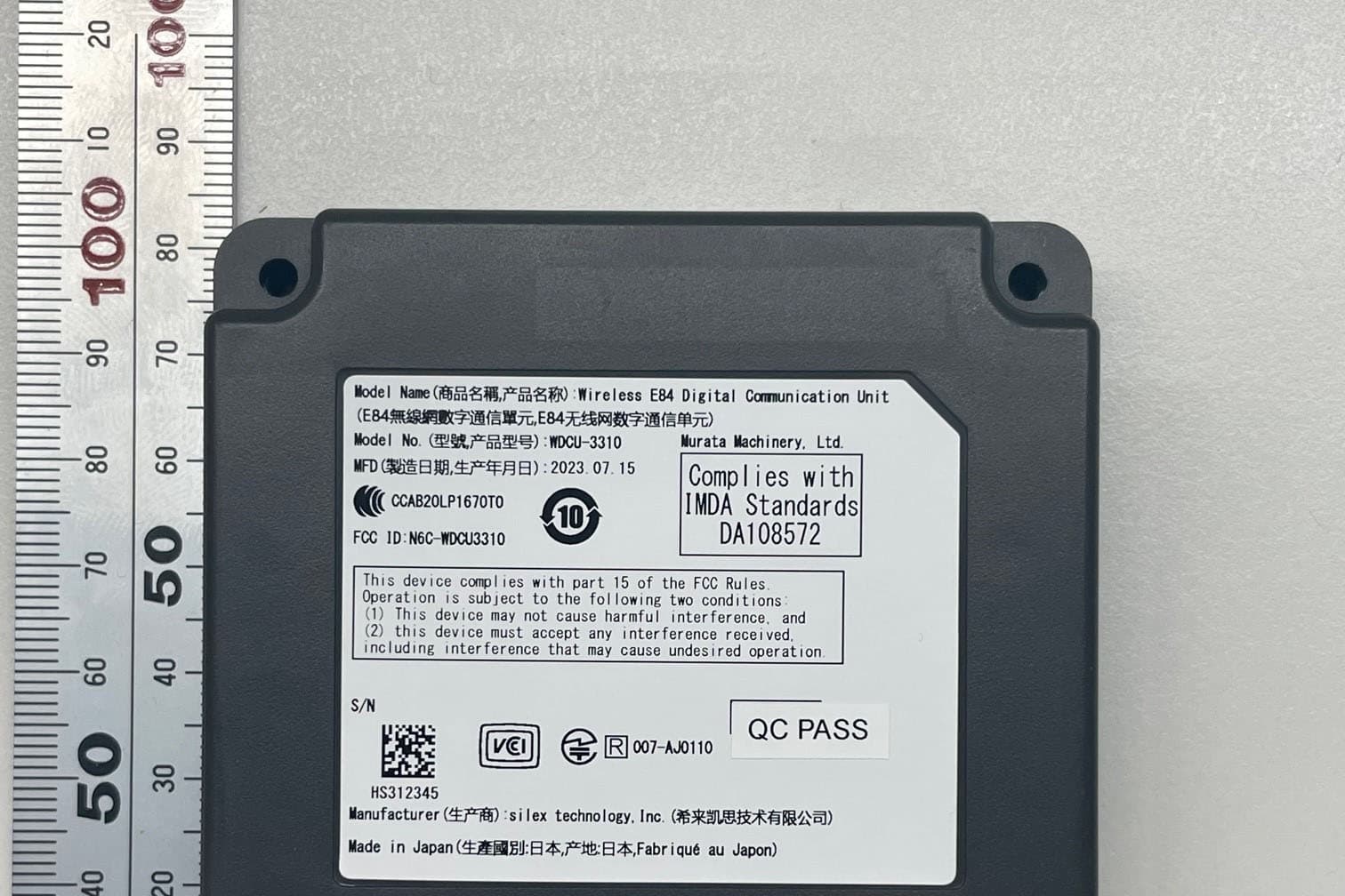
N6C-WDCU3310H
Oct 08, 2023Wireless E84 Digital Communication Unit
Equipment Class
NII - Unlicensed National Information Infrastructure TX
N6C-AP200AC
May 31, 2021Wireless LAN Access Point
Equipment Class
DTS - Digital Transmission System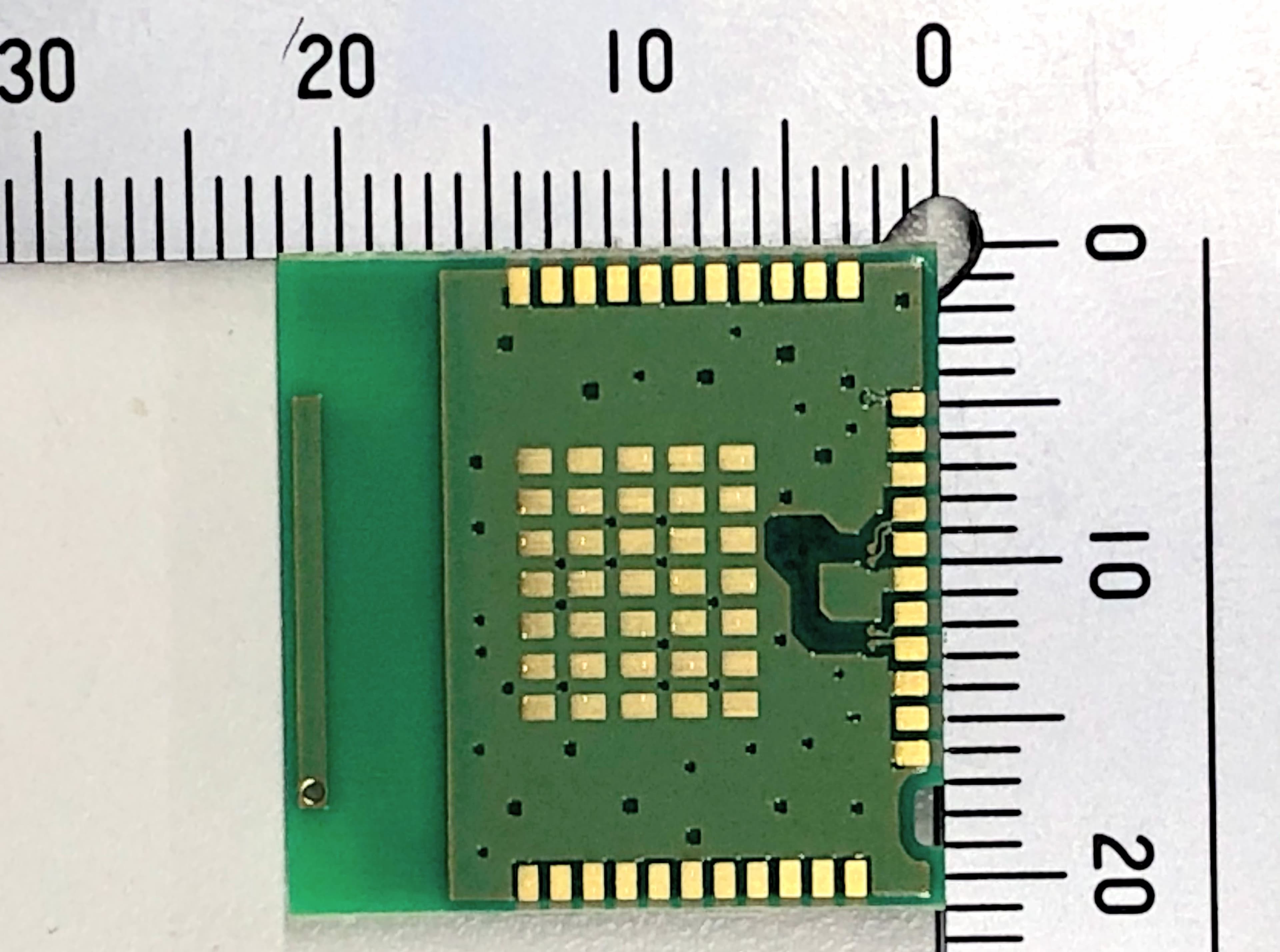
N6C-USBAC
Apr 19, 2021Embedded Wireless Module
Equipment Class
DTS - Digital Transmission System