N6C-SDMAN2Wireless LAN SDIO module
Silex Technology, Inc.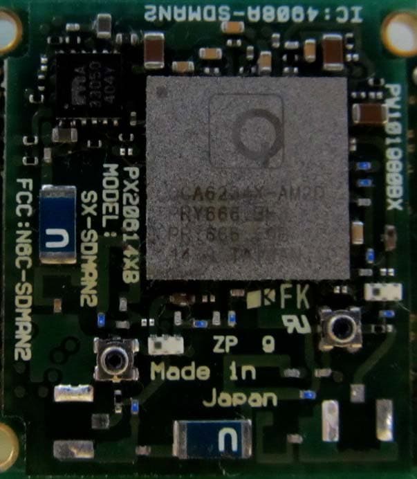
Click to zoom
Application Details
- Equipment Class
- NII - Unlicensed National Information Infrastructure TX
- Date of Grant
- Sep 07, 2015
- Application Purpose
- Original Equipment
- Date of Application
- Sep 07, 2015
- Equipment Note
- Wireless LAN SDIO module
- Frequency Range
- 5745.00000000 - 5825.00000000
- Company
- Silex Technology, Inc.
- Country
- Japan
Documents & Files
Document Text
Text extracted from the exhibit documents filed with the FCC. Open a document above to read the original.
Users Manual
User Manual Since this module is not sold to general end users directly, there is no user manual of module. For the details about this module, please refer to the specification sheet of module. This module should be installed in the host device according to the interface specification (installation procedure). The following information must be indicated on the host device of this module; [for FCC] Contains Transmitter Module FCC ID: N6C-SDMAN2 or Contains FCC ID: N6C-SDMAN2 [for IC] Contains Transmitter Module IC: 4908A-SDMAN2 or Contains IC: 4908A-SDMAN2 [for FCC and IC] This device complies with Part 15 of FCC Rules and Industry Canada’s licence-exempt RSSs. Operation is subject to the following two conditions: (1) this device may not cause harmful interference, and (2) this device must accept any interference received, including interference that may cause undesired operation. Le présent appareil est conforme à la partie 15 des règles de la FCC et aux normes des CNR d'Industrie Canada applicables aux appareils radio exempts de licence. L'exploitation est autorisée aux deux conditions suivantes : (1) l'appareil ne doit pas produire de brouillage, et (2) l'appareil doit accepter tout brouillage subi, même si le brouillage est susceptible d'en compromettre le fonctionnement. *If it is difficult to describe this statement on the host product due to the size, please describe in the User's manual. The following statements must be described on the user manual of the host device of this module; [for FCC] FCC CAUTION Changes or modifications not expressly approved by the party responsible for compliance could void the user’s authority to operate the equipment. This transmitter must not be co-located or operated in conjunction with any other antenna or transmitter. [for IC] 5150-5250MHz and 5250-5350MHz bands are restricted to indoor operations only. La bandes 5150-5250MHz et 5250-5350MHz ont restreints à une utilisation à l’intérieur seulement. High-power radars are allocated as primary users (i.e. priority users) of the bands 5250-5350 MHz and 5650-5850 MHz and that these radars could cause interference and/or damage to LE-LAN devices. Les radars de haute puissance sont désignés utilisateurs principaux (c.-à-d., qu'ils ont la priorité) pour les bandes 5250-5350 MHz et 5650-5850 MHz, et ces radars pourraient causer du brouillage et/ou des dommages aux dispositifs LAN-EL. [for FCC and IC] This equipment complies with FCC/IC radiation exposure limits set forth for an uncontrolled environment and meets the FCC radio frequency (RF) Exposure Guidelines and RSS-102 of the IC radio frequency (RF) Exposure rules. This equipment should be installed and operated keeping the radiator at least 20cm or more away from person’s body. Cet équipement est conforme aux limites d’exposition aux rayonnements énoncées pour un environnement non contrôlé et respecte les règles les radioélectriques (RF) de la FCC lignes directrices d'exposition et d’exposition aux fréquences radioélectriques (RF) CNR-102 de l’IC. Cet équipement doit être installé et utilisé en gardant une distance de 20 cm ou plus entre le radiateur et le corps humain.
External Photos
Photo Top Photo Bottom
External Photos
Photo Top with On board chip antenna Antenna
External Photos
Photo Top with External printed PCB antenna
ID Label/Location Info
Drawing No.:JW202160AX Date:July 10, 2015 (48/61) CONFIDENTIAL © silex technology, Inc. 8. マーキング仕様(Marking specifications) SMT version IC number FCC number Product name Country of origin
Internal Photos
Photo Top Photo Bottom
RF Exposure Info
UL Japan, Inc. Ise EMC Lab. 4383-326 Asama-cho, Ise-shi, Mie-ken 516-0021 JAPAN Telephone : +81 596 24 8999 Facsimile : +81 596 24 8124 Applicant: silex technology, Inc. Type of Equipment : Wireless LAN SDIO module Model No. : FCC ID: N6C-SDMAN2 ⇒ complies with FCC radiation exposure requirement specified in the FCC Rules 2.1091 (for mobile). RF Exposure Calculations: ← The following information provides the minimum separation distance for the highest gain from (B) Limits for General Population / Uncontrolled Exposure of TABLE 1- LIMITS FOR MAXIMUM PERMISSIBLE EXPOSURE (MPE) of §1.1310 Radiofrequency radiation exposure limits. This calculation is based on the highest EIRP possible from the system, considering maximum power and antenna gain, and considering a 1.0mW/cm^2 uncontrolled exposure limit. The Friis formula used was: S = (P * G) / (4* π * r 2 ) Where P = 28.27 mW (Maximum Average output power) G = 2.45 Numerical Antenna gain; equal to3.90dBi r =20.0 cm S = 0.01381 mW/cm 2 Even taking into account the tolerance, this device can be satisfied with the limits. For: SX-SDMAN2 (WLAN (5GHz band) Part) antenna provided with the “SX-SDMAN2 (WLAN (5GHz band) Part)“ as calculated No. : 10748020H RF Exposure / MPE Calculation SX-SDMAN2 (WLAN (5GHz band) Part) silex technology, Inc. declares that Model : SX-SDMAN2 (WLAN (5GHz band) Part)
Test Report
Test report No. : 10748020H-D-R1 Page : 2 of 22 Issued date : August 17, 2015 Revised date : September 7, 2015 FCC ID : N6C-SDMAN2 UL Japan, Inc. Ise EMC Lab. 4383-326 Asama-cho, Ise-shi, Mie-ken 516-0021 JAPAN Telephone : +81 596 24 8999 Facsimile : +81 596 24 8124 REVISION HISTORY Original Test Report No.: 10748020H-D Revision Test report No. Date Page revised Contents - (Original) 10748020H-D August 17, 2015 - - 1 10748020H-D-R1 September 7, 2015 P.5 Correction of Power Supply (inner) Test report No. : 10748020H-D-R1 Page : 3 of 22 Issued date : August 17, 2015 Revised date : September 7, 2015 FCC ID : N6C-SDMAN2 UL Japan, Inc. Ise EMC Lab. 4383-326 Asama-cho, Ise-shi, Mie-ken 516-0021 JAPAN Telephone : +81 596 24 8999 Facsimile : +81 596 24 8124 CONTENTS PAGE SECTION 1: Customer information ...................................................................................................................... 4 SECTION 2: Equipment under test (E.U.T.) ........................................................................................................ 4 SECTION 3: Scope of Report................................................................................................................................. 6 SECTION 4: Test specification, procedures & results ......................................................................................... 6 SECTION 5: Operation of E.U.T. during testing ............................................................................................... 11 SECTION 6: Channel Move Time, Channel Closing Transmission Time ....................................................... 17 SECTION 7: Non-Occupancy Period .................................................................................................................. 19 APPENDIX 1: Test instruments ........................................................................................................................... 21 APPENDIX 2: Photographs of test setup ............................................................................................................ 22 Test report No. : 10748020H-D-R1 Page : 4 of 22 Issued date : August 17, 2015 Revised date : September 7, 2015 FCC ID : N6C-SDMAN2 UL Japan, Inc. Ise EMC Lab. 4383-326 Asama-cho, Ise-shi, Mie-ken 516-0021 JAPAN Telephone : +81 596 24 8999 Facsimile : +81 596 24 8124 SECTION 1: Customer information Company Name : silex technology, Inc. Address : 2-3-1 Hikaridai, Seika-cho, Kyoto 619-0237, Japan Telephone Number : +81-774-98-3878 Facsimile Number : +81-774-98-3758 Contact Person : Toshiro Kometani SECTION 2: Equipment under test (E.U.T.) 2.1 Identification of E.U.T. Type of Equipment : Wireless LAN SDIO module Model No. : SX-SDMAN2 Serial No. : Refer to Section 4, Clause 4.2 Rating : DC 3.3 V, DC 1.8 V Receipt Date of Sample : April 17, 2015 Country of Mass-production : Japan Condition of EUT : Production prototype (Not for Sale: This sample is equivalent to mass-produced items.) Modification of EUT : No Modification by the test lab 2.2 Product Description Model: SX-SDMAN2 (referred to as the EUT in this report) is a Wireless LAN SDIO module. General Specification Clock frequency(ies) in the system : 26 MHz Operating Temperature : -20 deg. C - +85 deg. C Test report No. : 10748020H-D-R1 Page : 5 of 22 Issued date : August 17, 2015 Revised date : September 7, 2015 FCC ID : N6C-SDMAN2 UL Japan, Inc. Ise EMC Lab. 4383-326 Asama-cho, Ise-shi, Mie-ken 516-0021 JAPAN Telephone : +81 596 24 8999 Facsimile : +81 596 24 8124 Radio Specification Radio Type : Transceiver Method of Frequency Generation : Synthesizer Power Supply (inner) : DC 1.27 V IEEE802.11b IEEE802.11g/n (20 M band) IEEE802.11a/n (20 M band) IEEE802.11n (40 M band) Bluetooth Ver.4.0 with EDR function Frequency of operation 2412 MHz - 2462 MHz 2412 MHz - 2462 MHz5180 MHz - 5240 MHz 5260 MHz - 5320 MHz *1) 5500 MHz - 5700 MHz *1) 5745 MHz - 5825 MHz 5190 MHz - 5230 MHz 5270 MHz - 5310 MHz *1) 5510 MHz - 5670 MHz *1) 5755 MHz - 5795 MHz 2402 MHz - 2480 MHz Type of modulation DSSS (CCK, DQPSK, DBPSK) OFDM-CCK (64QAM, 16QAM, QPSK, BPSK) OFDM (64QAM, 16QAM, QPSK, BPSK) BT: FHSS (GFSK, π/4-DQPSK, 8- DPSK) LE: GFSK Channel spacing 5MHz 20MHz 40MHz BT: 1MHz LE: 2MHz Antenna type [Antenna 1] Antenna port 0: External antenna (WLAN) Antenna port 1: External antenna (WLAN / Bluetooth) [Antenna 2] Antenna port 0: Chip antenna (WLAN) Antenna port 1: Chip antenna (WLAN / Bluetooth) Antenna Connector type Antenna 1: U.FL Alternative connector Antenna 2: none Antenna Gain Antenna 1: 1.8 dBi (2.4 GHz Band), 3.9 dBi (5 GHz Band) Antenna 2: 1.4 dBi (2.4 GHz Band), 2.3 dBi (5 GHz Band) *1) This test report applies to WLAN (5 GHz Band [5260 - 5320 MHz, 5500 - 5700 MHz, 5270 - 5310 MHz, 5510 - 5670 MHz]). * WLAN and Bluetooth do not transmit simultaneously. Test report No. : 10748020H-D-R1 Page : 6 of 22 Issued date : August 17, 2015 Revised date : September 7, 2015 FCC ID : N6C-SDMAN2 UL Japan, Inc. Ise EMC Lab. 4383-326 Asama-cho, Ise-shi, Mie-ken 516-0021 JAPAN Telephone : +81 596 24 8999 Facsimile : +81 596 24 8124 SECTION 3: Scope of Report This report only covers DFS requirement, as specified by the following referenced procedures. SECTION 4: Test specification, procedures & results 4.1 Test Specification Test Specification : FCC Part 15 Subpart E: 2015, final revised on June 12, 2015 and effective July 13, 2015 Title : FCC 47CFR Part15 Radio Frequency Device Subpart E Unlicensed National Information Infrastructure Devices Section 15.407 General technical requirements * The revision on June 12, 2015 does not affect the test specification applied to the EUT. Test Specification : KDB905462 D02 UNII DFS Compliance Procedures New Rules v01r02 Title : COMPLIANCE MEASUREMENT PROCEDURES FOR UNLICENSED- NATIONAL INFORMATION INFRASTRUCTURE DEVICES OPERATING IN THE 5250-5350MHz AND 5470-5725MHz BANDS INCORPORATING DYNAMIC FREQUENCY SELECTION Test Specification : KDB905462 D03 Client Without DFS New …
Text truncated - open the document above for the full version.
Test Report
Test report No. : 10748020H-C-R1 Page : 2 of 109 Issued date : August 17, 2015 Revised date : September 7, 2015 FCC ID : N6C-SDMAN2 UL Japan, Inc. Ise EMC Lab. 4383-326 Asama-cho, Ise-shi, Mie-ken 516-0021 JAPAN Telephone : +81 596 24 8999 Facsimile : +81 596 24 8124 REVISION HISTORY Original Test Report No.: 10748020H-C Revision Test report No. Date Page revised Contents - (Original) 10748020H-C August 17, 2015 - - 1 10748020H-C-R1 September 7, 2015 P.5 Correction of Power Supply (inner) Test report No. : 10748020H-C-R1 Page : 3 of 109 Issued date : August 17, 2015 Revised date : September 7, 2015 FCC ID : N6C-SDMAN2 UL Japan, Inc. Ise EMC Lab. 4383-326 Asama-cho, Ise-shi, Mie-ken 516-0021 JAPAN Telephone : +81 596 24 8999 Facsimile : +81 596 24 8124 CONTENTS PAGE SECTION 1: Customer information ....................................................................................................... 4 SECTION 2: Equipment under test (E.U.T.) ......................................................................................... 4 SECTION 3: Test specification, procedures & results .......................................................................... 6 SECTION 4: Operation of E.U.T. during testing .................................................................................. 9 SECTION 5: Conducted Emission .........................................................................................................14 SECTION 6: Radiated Spurious Emission and Band Edge Compliance ...........................................15 SECTION 7: Antenna Terminal Conducted Tests ...............................................................................17 APPENDIX 1: Test data ..........................................................................................................................18 Conducted Emission ........................................................................................................................18 26dB Emission Bandwidth and 99% Occupied Bandwidth .............................................................19 20dB Bandwidth ..............................................................................................................................29 6dB Bandwidth ................................................................................................................................36 Maximum Conducted Output Power ...............................................................................................40 Maximum Power Spectral Density ..................................................................................................49 Radiated Spurious Emission ............................................................................................................61 Band Edge confirmation ..................................................................................................................98 Conducted Spurious Emission .......................................................................................................102 APPENDIX 2: Test instruments ...........................................................................................................103 APPENDIX 3: Photographs of test setup ............................................................................................105 Conducted Emission ......................................................................................................................105 Radiated Spurious Emission ..........................................................................................................106 Test report No. : 10748020H-C-R1 Page : 4 of 109 Issued date : August 17, 2015 Revised date : September 7, 2015 FCC ID : N6C-SDMAN2 UL Japan, Inc. Ise EMC Lab. 4383-326 Asama-cho, Ise-shi, Mie-ken 516-0021 JAPAN Telephone : +81 596 24 8999 Facsimile : +81 596 24 8124 SECTION 1: Customer information Company Name : silex technology, Inc. Address : 2-3-1 Hikaridai, Seika-cho, Kyoto 619-0237, Japan Telephone Number : +81-774-98-3878 Facsimile Number : +81-774-98-3758 Contact Person : Toshiro Kometani SECTION 2: Equipment under test (E.U.T.) 2.1 Identification of E.U.T. Type of Equipment : Wireless LAN SDIO module Model No. : SX-SDMAN2 Serial No. : Refer to Clause 4.2 Rating : DC 3.3 V Receipt Date of Sample : April 20, 2015 Country of Mass-production : Japan Condition of EUT : Production prototype (Not for Sale: This sample is equivalent to mass-produced items.) Modification of EUT : No Modification by the test lab Test report No. : 10748020H-C-R1 Page : 5 of 109 Issued date : August 17, 2015 Revised date : September 7, 2015 FCC ID : N6C-SDMAN2 UL Japan, Inc. Ise EMC Lab. 4383-326 Asama-cho, Ise-shi, Mie-ken 516-0021 JAPAN Telephone : +81 596 24 8999 Facsimile : +81 596 24 8124 2.2 Product Description Model: SX-SDMAN2 (referred to as the EUT in this report) is a Wireless LAN SDIO module. General Specification Clock frequency(ies) in the system : 26 MHz Operating Temperature : -20 deg. C - +85 deg. C Radio Specification Radio Type : Transceiver Method of Frequency Generation : Synthesizer Power Supply (inner) : DC 1.27 V IEEE802.11b IEEE802.11g/n (20 M band) IEEE802.11a/n (20 M band) IEEE802.11n (40 M band) Bluetooth Ver.4.0 with EDR function Frequency of operation 2412 MHz - 2462 MHz 2412 MHz - 2462 MHz 5180 MHz - 5240 MHz *1) 5260 MHz - 5320 MHz *1) 5500 MHz - 5700 MHz *1) 5745 MHz - 5825 MHz *1) 5190 MHz - 5230 MHz *1) 5270 MHz - 5310 MHz *1) 5510 MHz - 5670 MHz *1) 5755 MHz - 5795 MHz *1) 2402 MHz - 2480 MHz Type of modulation DSSS (CCK, DQPSK, DBPSK) OFDM-CCK (64QAM, 16QAM, QPSK, BPSK) OFDM (64QAM, 16QAM, QPSK, BPSK) BT: FHSS (GFSK, π/4-DQPSK, 8- DPSK) LE: GFSK Channel spacing 5 MHz 20 MHz 40 MHz BT: 1 MHz LE: 2 MHz Antenna type [Antenna 1] Antenna port 0: External antenna (WLAN) Antenna port 1: External antenna (WLAN / Bluetooth) [Antenna 2] Antenna port 0: Chip antenna (WLAN) Antenna port 1: Chip antenna (WLAN / Bluetooth) Antenna Connector type Antenna 1: …
Text truncated - open the document above for the full version.
Test Setup Photos
Test report No. : 10748020H-D-R1 Page : 22 of 22 Issued date : August 17, 2015 Revised date : September 7, 2015 FCC ID : N6C-SDMAN2 UL Japan, Inc. Ise EMC Lab. 4383-326 Asama-cho, Ise-shi, Mie-ken 516-0021 JAPAN Telephone : +81 596 24 8999 Facsimile : +81 596 24 8124 APPENDIX 2: Photographs of test setup Photo 1 Photo 2 End of Report
Test Setup Photos
Test report No. : 10748020H-C-R1 Page : 105 of 109 Issued date : August 17, 2015 Revised date : September 7, 2015 FCC ID : N6C-SDMAN2 UL Japan, Inc. Ise EMC Lab. 4383-326 Asama-cho, Ise-shi, Mie-ken 516-0021 JAPAN Telephone : +81 596 24 8999 Facsimile : +81 596 24 8124 APPENDIX 3: Photographs of test setup Conducted Emission Photo 1 Photo 2 Test report No. : 10748020H-C-R1 Page : 106 of 109 Issued date : August 17, 2015 Revised date : September 7, 2015 FCC ID : N6C-SDMAN2 UL Japan, Inc. Ise EMC Lab. 4383-326 Asama-cho, Ise-shi, Mie-ken 516-0021 JAPAN Telephone : +81 596 24 8999 Facsimile : +81 596 24 8124 Radiated Spurious Emission (Antenna 1) Photo 1 Photo 2 Test report No. : 10748020H-C-R1 Page : 107 of 109 Issued date : August 17, 2015 Revised date : September 7, 2015 FCC ID : N6C-SDMAN2 UL Japan, Inc. Ise EMC Lab. 4383-326 Asama-cho, Ise-shi, Mie-ken 516-0021 JAPAN Telephone : +81 596 24 8999 Facsimile : +81 596 24 8124 Worst Case Position (Module and Antenna 1) Above 1GHz (Horizontal: Module Z / Ant X-axis/ Vertical: Module Z / Ant Y-axis) Below 1GHz (Horizontal: Module Y / Ant X-axis/ Vertical: Module Y / Ant X-axis) Module Antenna 1 X-axis X-axis Y-axis Y-axis Z-axis Z-axis Test report No. : 10748020H-C-R1 Page : 108 of 109 Issued date : August 17, 2015 Revised date : September 7, 2015 FCC ID : N6C-SDMAN2 UL Japan, Inc. Ise EMC Lab. 4383-326 Asama-cho, Ise-shi, Mie-ken 516-0021 JAPAN Telephone : +81 596 24 8999 Facsimile : +81 596 24 8124 Radiated Spurious Emission (Antenna 2) Photo 1 Photo 2 Test report No. : 10748020H-C-R1 Page : 109 of 109 Issued date : August 17, 2015 Revised date : September 7, 2015 FCC ID : N6C-SDMAN2 UL Japan, Inc. Ise EMC Lab. 4383-326 Asama-cho, Ise-shi, Mie-ken 516-0021 JAPAN Telephone : +81 596 24 8999 Facsimile : +81 596 24 8124 Worst Case Position (Antenna 2) Above 1GHz (Horizontal:Y-axis Vertical: Y-axis) Below 1GHz (Horizontal:Y-axis Vertical: Z-axis) X-axis Y-axis Z-axis End of Report
Contact Information
Applicant
Yoshinori Nakai(General Manager)
Technical Contact
UL Japan, Inc.Takahiro Hatakeda
[email protected]81-596-24-8999
4383-326 Asama-cho, Ise-shi · Mie-ken · Japan
Test Firm
UL Japan, Inc. Head office EMC Lab.Tetsuya Hashimoto
Technical Specifications
| # | Rule Parts | Frequency Range | Power Output |
|---|---|---|---|
| 3 | 15E | 5.75 GHz - 5.83 GHz | 25.40 mW |
Other Applications from Silex Technology, Inc.
N6C-SDMAX6E
Mar 26, 2026SX-SDMAX6E
Equipment Class
DTS - Digital Transmission System
N6C-SDMAH
Feb 04, 2024Embedded Wireless Module
Equipment Class
DTS - Digital Transmission System
N6C-WDCU3310H
Oct 08, 2023Wireless E84 Digital Communication Unit
Equipment Class
NII - Unlicensed National Information Infrastructure TX
N6C-AP200AC
May 31, 2021Wireless LAN Access Point
Equipment Class
DTS - Digital Transmission System
N6C-USBAC
Apr 19, 2021Embedded Wireless Module
Equipment Class
DTS - Digital Transmission System