N6C-SX10WGWireless 802.11b/g transmitter module
Silex Technology, Inc.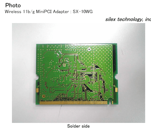
Click to zoom
Application Details
- Equipment Class
- DTS - Digital Transmission System
- Date of Grant
- Oct 19, 2005
- Application Purpose
- Original Equipment
- Date of Application
- Oct 19, 2005
- Equipment Note
- Wireless 802.11b/g transmitter module
- Frequency Range
- 2412.00000000 - 2462.00000000
- Company
- Silex Technology, Inc.
- Country
- Japan
Documents & Files
Document Text
Text extracted from the exhibit documents filed with the FCC. Open a document above to read the original.
Users Manual
Hardwarespecifications/Compliance2 2System Requirements4 3Setup 4 SX-10WG Users Manual FCC IDN6C-SX10WG NOTICE This equipment has been tested and found to comply with the limits for a Class B digital device, pursuant to part 15 of the FCC Rules. These limits are designed to provide reasonable protection against harmful interference in a residential installation. This equipment generates, uses and can radiate radio frequency energy and, if not installed and used in accordance with the instructions, may cause harmful interference to radio communications. However, there is no guarantee that interference will not occur in a particular installation. If this equipment does cause harmful interference to radio or television reception, which can be determined by turning the equipment off and on, the user is encouraged to try to correct the interference by one or more of the following measures: -Reorient or relocate the receiving antenna -Increase the separation between the equipment and receiver. -Connect the equipment into an outlet on a circuit different from that to which the receiver is connected. -Consult the dealer or an experienced radio/TV technician for help. This transmitter must not be co-located or operated in conjunction with any other antenna or transmitter. This equipment complies with FCC radiation exposure limits set forth for uncontrolled equipment and meets the FCC radio frequency (RF) Exposure Guidelines in Supplement C to OET65. This equipment should be installed and operated with at least 20cm and more between the radiator and person’s body (excluding extremities: hands, wrists, feet and legs). This device complies with Part 15 of the FCC Rules. Operation is subject to the following two conditions: (1) this device may not cause harmful interference, and (2) this device must accept any interference received, including interference that may cause undesired operation FCC WARNING Changes or modifications not expressly approved by the party responsible for compliance could void the user’s authority to operate the equipment. 1Hardwarespecifications/Compliance Operating environment Temperature+0°C to +55°C, +32F to +131F Humidity20% to 90% Storage environment Temperature-10°C to +60°C, +14F to +140F Humidity5% to 90% supply voltage 3.3V 0.3V Host I/F MiniPCI IEEE802.11b Frequency : 2.4GHz Transmission system DS-SS Transmission speed 1M/2M/5.5M/11M Automatic detection Channel1-11ch IEEE802.11g Frequency : 2.4GHz Transmission systemOFDM Transmission speed 6M/12M/18M/36M/48M/54M Automatic detection Channel1-11ch Antenna interface Diversity connector Laptop/ PC containing: . 32-bit CardBus slot (or Desktop PC with PC Card-PCI adapter) . Mini PCI . 32 MB memory or greater . 300 MHz processor or higher It uses Driver and a utility of Atheros Communications. AR5BMB5 client utility It completes installation according to setup Wizard. 2System Requirements 3Setup
ID Label/Location Info
Label Specification(unit[mm]) Label Position Label SX-10WG
Test Report
Test report No. : 25JE0262-HO-1a Page : 1 of 75 Issued date : September 27, 2005 Revised date : October 5, 2005 FCC ID : N6C-SX10WG UL Apex Co., Ltd. Head Office EMC Lab. 4383-326 Asama-cho, Ise-shi, Mie-ken 516-0021 JAPAN Telephone : +81 596 24 8116 Facsimile : +81 596 24 8124 MF060b(01.06.05) EMI TEST REPORT Test Report No. : 25JE0262-HO-1a Applicant : silex technology, Inc. Type of Equipment : Wireless 11g MiniPCI Adapter Model No. : SX-10WG FCC ID : N6C-SX10WG Test standard : FCC Part 15 Subpart C Section 15.207, Section 15.247: 2005 Test Result : Complied 1. This test report shall not be reproduced in full or partial, without the written approval of UL Apex Co., Ltd. 2. The results in this report apply only to the sample tested. 3. This equipment is in compliance with the above regulation. We hereby certify that the data contain a true representation of the EMC profile. 4. The test results in this report are traceable to the national or international standards. Date of test: _____________________________ Tested by: ______________________________ _______________________________ Takumi Shimada EMC Services Mitsuru Fujimura EMC Services _____________________________________________________________ Kenichi Adachi EMC Services Yutaka Yoshida EMC Services Approved by : ______________________________ Naoki Sakamoto Group Leader of EMC Services August 5 to September 16, 2005 Test report No. : 25JE0262-HO-1a Page : 2 of 75 Issued date : September 27, 2005 Revised date : October 5, 2005 FCC ID : N6C-SX10WG UL Apex Co., Ltd. Head Office EMC Lab. 4383-326 Asama-cho, Ise-shi, Mie-ken 516-0021 JAPAN Telephone : +81 596 24 8116 Facsimile : +81 596 24 8124 MF060b(01.06.05) CONTENTS PAGE SECTION 1: Client information ......................................................................................................... 3 SECTION 2: Equipment under test (E.U.T.)..................................................................................... 3 SECTION 3: Test specification, procedures & results...................................................................... 5 SECTION 4: Operation of E.U.T. during testing .............................................................................. 8 SECTION 5: Conducted Emission.................................................................................................... 10 SECTION 6: Bandwidth .................................................................................................................... 10 SECTION 7: Maximum Peak Output Power .................................................................................. 10 SECTION 8: Spurious Emission....................................................................................................... 11 SECTION 9: Peak Power Density..................................................................................................... 11 APPENDIX 1: Photographs of test setup .........................................................................................12 Conducted Emission ................................................................................................................................. 12 Spurious Emission (Radiated) ................................................................................................................. 13 Worst Case Position .................................................................................................................................. 14 APPENDIX 2:Test instruments ......................................................................................................... 15 APPENDIX 3: Data of EMI test......................................................................................................... 17 Conducted Emission ................................................................................................................................. 17 6dB Bandwidth.......................................................................................................................................... 23 Maximum Peak Output Power ................................................................................................................ 26 Radiated Spurious Emission .................................................................................................................... 31 Conducted Spurious Emission ................................................................................................................. 58 Conducted emission Band Edge compliance .......................................................................................... 64 Power Density............................................................................................................................................ 65 99%Occupied Bandwidth ........................................................................................................................ 68 APPENDIX 4: Reference data (Maximum Peak Output Power).................................................... 70 Test report No. : 25JE0262-HO-1a Page : 3 of 75 Issued date : September 27, 2005 Revised date : October 5, 2005 FCC ID : N6C-SX10WG UL Apex Co., Ltd. Head Office EMC Lab. 4383-326 Asama-cho, Ise-shi, Mie-ken 516-0021 JAPAN Telephone : +81 596 24 8116 Facsimile : +81 596 24 8124 MF060b(01.06.05) SECTION 1: Client information Company Name : silex technology, Inc. Address : 15-15 Takaida Higashi-Osaka-shi Osaka, 577-0802 Japan Telephone Number : +81-6-6784-3758 Facsimile Number : +81-6-6784-3750 Contact Person : Toshirou Kometani SECTION 2: Equipment under test (E.U.T.) 2.1 Identification of E.U.T. Type of Equipment : Wireless 11g MiniPCI Adapter Model No. : SX-10WG Serial No. : 10 (for Radiated emission (1G-10GHz)) 20 (for Antenna Terminal, Conducted Emission and Radiated Emission ( 30MHz-1GHz, 10-26.5GHz) tests) Country of Manufacture : JAPAN Rating : DC3.3V(+/-10%) / 0.5A Receipt Date of Sample : July 5 2005 Condition of EUT : Production Prototype (Not f…
Text truncated - open the document above for the full version.
Test Setup Photos
Test report No. : 25JE0262-HO-1a Page : 12 of 75 Issued date : September 27, 2005 Revised date : October 5, 2005 FCC ID : N6C-SX10WG UL Apex Co., Ltd. Head Office EMC Lab. 4383-326 Asama-cho, Ise-shi, Mie-ken 516-0021 JAPAN Telephone : +81 596 24 8116 Facsimile : +81 596 24 8124 MF060b(01.06.05) APPENDIX 1: Photographs of test setup Conducted Emission Front Rear Test report No. : 25JE0262-HO-1a Page : 13 of 75 Issued date : September 27, 2005 Revised date : October 5, 2005 FCC ID : N6C-SX10WG UL Apex Co., Ltd. Head Office EMC Lab. 4383-326 Asama-cho, Ise-shi, Mie-ken 516-0021 JAPAN Telephone : +81 596 24 8116 Facsimile : +81 596 24 8124 MF060b(01.06.05) Spurious Emission (Radiated) Front Rear Test report No. : 25JE0262-HO-1a Page : 14 of 75 Issued date : September 27, 2005 Revised date : October 5, 2005 FCC ID : N6C-SX10WG UL Apex Co., Ltd. Head Office EMC Lab. 4383-326 Asama-cho, Ise-shi, Mie-ken 516-0021 JAPAN Telephone : +81 596 24 8116 Facsimile : +81 596 24 8124 MF060b(01.06.05) Worst Case Position 30MHz-1GHz: Z-axis:Horizontal / Z-axis:Vertical Above 1GHz: Z-axis:Horizontal / X-axis: Vertical X-axis Y-axis Z-axis
Contact Information
Applicant
Yukinari Shibuya(Manager)
Technical Contact
UL Apex Co., LtdNaoki Sakamoto
[email protected]+81-596-24-8116
4383-326 Asama-cho · Ise-shi, Mie-ken · Japan
Non-Technical Contact
UL Apex Co., LtdYoshiko Mizuta
[email protected]+81-596-24-8116
Test Firm
UL Japan, IncMitsuru Fujimura
Technical Specifications
| # | Rule Parts | Frequency Range | Power Output |
|---|---|---|---|
| 1 | 15C | 2.41 GHz - 2.46 GHz | 108.63 mW |
Other Applications from Silex Technology, Inc.
N6C-SDMAX6E
Mar 26, 2026SX-SDMAX6E
Equipment Class
DTS - Digital Transmission System
N6C-SDMAH
Feb 04, 2024Embedded Wireless Module
Equipment Class
DTS - Digital Transmission System
N6C-WDCU3310H
Oct 08, 2023Wireless E84 Digital Communication Unit
Equipment Class
NII - Unlicensed National Information Infrastructure TX
N6C-AP200AC
May 31, 2021Wireless LAN Access Point
Equipment Class
DTS - Digital Transmission System
N6C-USBAC
Apr 19, 2021Embedded Wireless Module
Equipment Class
DTS - Digital Transmission System