N6N2012061803HEVM-550Tx
Vivax-Metrotech (Shanghai) Ltd.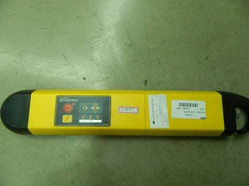
Click to zoom
Application Details
- Equipment Class
- DCD - Part 15 Low Power Transmitter Below 1705 kHz
- Date of Grant
- Aug 08, 2012
- Application Purpose
- Original Equipment
- Date of Application
- Jul 30, 2012
- Equipment Note
- VM-550Tx
- Frequency Range
- 0.08300000 - 0.08300000
- Country
- China
Documents & Files
Document Text
Text extracted from the exhibit documents filed with the FCC. Open a document above to read the original.
Users Manual
Depth Measurement / Frequency Selection Sensitivity Control (increase sensitivity) On/Off ControlLong press to switch on/off. Short press to change speaker volume. Increment sensitivity up, or auto scale to 50% if off scale. When in frequency select menu use this button to scroll forwards through available frequencies. Short press to initiate depth measurement. Long press to enter frequency select menu then short press to exit menu. 4 2 3 1234 VM-550/VM-560 User Guide V1.0 Introduction This guide describes the operation of the VM-550 and VM-560 pipe and cable locators. Both are general purpose locators used to detect buried pipe and cable services in a variety of situations. The operations of the two systems are very similar. The main difference is in the operational frequencies: • VM-550 Frequencies: 50 or 60Hz, 8 kHz, 83 kHz • VM-560 Frequencies: 50 or 60Hz, 8 kHz, 480 kHz The VM-550/VM-560 is supplied with 1 watt transmitter with both direct connection and induction capabilities. An inductive clamp and LPC live separation filter are also available as optional accessories. To make a direct connection to a pipe or a de-energized cable conductor or cable sheath. To make a ground connection to complete a direct connection circuit. To make an inductive coupling connection to a live cable or pipe. Receiver Display Functions 1Battery Level Indicator 2Speaker Level Indicator 3Percentage Signal Levels 4Selected Locate Frequency 5Signal Level Indicator 6Sensitivity Setting Indicator Receiver Operational Controls 1 2 3 4 5 6 7 8 9 ON/OFF (Long press until Power ON indicator is on, long press again to turn off) Power ON Indicator Low Output Power Selected High Output Power Selected Speaker Frequency Select Frequency Selected Indicators Battery Cover Retaining Screws Battery Housing Cover Transmitter Operational Controls Accessories 1 2 3 4 Direct Connection Leads Ground Stake Signal Clamp Power Mode Operation Switch on the unit by pressing the ON/OFF pushbutton. Allow a few seconds to switch on. The frequency selected as shown on the display. If this is not the desired locate frequency (ie 50 or 60Hz) change as indicated below. NOTE The battery condition as indicated on battery icon. Replace batteries if necessary. See Changing Batteries Section. Changing the Locate Frequency Press and hold the depth measurement/frequency selection pushbutton until the frequency menu is entered. The display will show the present frequency selected in large numeric’s in the centre of the screen. Use the “+” or “–” pushbuttons to select the desired frequency. Press the depth measurement/frequency selection pushbutton to re-enter the locate screen. Locating a Cable in the Power (50/60Hz) Mode 1. Hold the locator vertically in the area that is required to be searched. Press the “+” or “-” pushbuttons to set the gain so that the bar graph reads approximately 50%. 2. Hold the locator in front of you in the orientation shown below. 3. Sweep the locator left to right along the suspected route of the cable. As the locator approaches the cable the meter reading will increase. Pinpoint the position by detecting the largest signal. Adjust the sensitivity of the locator by pressing the “+” or “-” pushbuttons to keep the signal on scale. 4. To confirm the direction of the cable, rotate the locator until the largest signal is detected. The direction of the cable is then directly ahead. 5. Continue to locate the cable along the route. 6. Depth measurements are not possible in the power (50/60Hz) mode, if pressed by accident it will show N/A. WARNING The power mode is used to detect signals radiating from cables or services that are carrying a 50 or 60Hz load. It is possible for a cable to be live but not carry a load. In this case there may not be a signal to be detected. Similarly, if a cable is exactly balanced the resulting signal radiating from the cable may be zero and therefore not detectable. Do NOT use the VM-550/VM-560 to identify if cables are live. Always dig with caution. Active Cable and Pipe Locating Detecting a cable or pipe can be achieved by applying a locate tone to a cable or pipe from a transmitter. This is called active locating. The locate tone can be applied by either. • Direct Connection • Induction Mode • Signal Clamp Mode Direct Connection Mode This method involves making a direct connection to the Cable or Pipe. WARNING DO NOT attempt to make a connection to a live conductor. Only make a connection to de-energized or dead cables. It is possible to connect to the sheath of active cables but this should only be attempted by qualified and authorized personnel. Method: Plug the direct connection leads to the transmitter. Connect the red lead to the cable or pipe and the black one to a suitable ground. Ideally this should be a ground stake placed at right angles to the probable route of the target line. If it is not possible to use a ground stake, connect the black lead to a grounded structure such as the rim of a manhole cover or other buried metallic structure. Try to avoid fencing as this will create interference from the return signal travelling along the fence. If necessary clean the connection point with a wire brush to ensure a good electrical connection. Select the desired frequency by pressing the “f” pushbutton. As a general rule the higher frequency will have a cleaner more stable reading and will jump insulation joints on pipes but has the disadvantage that it is more likely to jump to other utility nearby. The lower frequency is better for tracing a particular utility as it is more likely to keep to the utility line the transmitter is attached to. If in doubt, start with the lower frequency and switch to the higher one if it is not possible to detect a stable reading. The same applies to setting the signal level. A short press on the 61 83k 1 2 3 4 5 6 To safely inject a trace tone to a live cable via a domestic mains socket, so that the cable can be traced from the premises to the connection i…
Text truncated - open the document above for the full version.
Attestation Statements
Declaration about FCC approval American Certification Body, Inc. 6731 Whittier Avenue Suite C110 McLean, VA 22101 To Whom It May Concern: We, ______Vivax-Metrotech (Shanghai) Ltd._____ are aware of the fact the device under 15.213 shall be verified pursuant to the procedures in Subpart J of part 2. Nevertheless, certification is chosen as the approval method of this product. Thank you, Print name: Snow yang On behalf of Vivax-Metrotech (Shanghai) Ltd. July 30, 2012
Cover Letter(s)
022311 – 6 Request for Confidentiality Date: ____ 2012-06-18_____ Subject: Confidentiality Request for: ______FCC ID:N6N2012061803HE_____ Pursuant to FCC 47 CRF 0.457(d) and 0.459 and IC RSP-100, Section 10, the applicant requests that a part of the subject FCC application be held confidential. Type of Confidentiality Requested Exhibit Short Term PermanentBlock Diagrams Short Term External Photos Short Term Permanent* 2 Internal Photos Short Term Permanent Operation Description/Theory of Operation Short Term Permanent Parts List & Placement/BOM Short Term Permanent Tune-Up Procedure Short Term Permanent Schematics Short Term Test Setup Photos Short Term Permanent* User’s Manual *Note: ______(Insert Explanation as Necessary)______ _____Vivax-Metrotech (Shanghai) Ltd.____ has spent substantial effort in developing this product and it is one of the first of its kind in industry. Having the subject information easily available to "competition" would negate the advantage they have achieved by developing this product. Not protecting the details of the design will result in financial hardship. Permanent Confidentiality: The applicant requests the exhibits listed above as permanently confidential be permanently withheld from public review due to materials that contain trade secrets and proprietary information not customarily released to the public. Short-Term Confidentiality: The applicant requests the exhibits selected above as short term confidential be withheld from public view for a period of ___160 3 ___ days from the date of the Grant of Equipment Authorization and prior to marketing. This is to avoid premature release of sensitive information prior to marketing or release of the product to the public. Applicant is also aware that they are responsible to notify ACB in the event information regarding the product or the product is made available to the public. ACB will then release the documents listed above for public disclosure pursuant to FCC Public Notice DA 04-1705. NOTE for Industry Canada Applications: The applicant understands that until such time that IC distinguishes between Short Term and Permanent Confidentiality, either type of marked exhibit above will simply be marked Confidential when submitted to IC. Sincerely, By: _____ ________ __________ Snow yang_________ (Signature/Title 4 ) (Print name) 2 - The asterisked items (*) require further justification before permanent confidentiality will be allowed. These also currently require review by the FCC under their Permit-But-Ask policy before the grant is issued and can delay completion of an application. Further justification should be added to the note above. One such example for a potted device would be: “The EUT is FULLY potted using a non-removable epoxy based material. Removal of potting material causes irreparable damage to internal circuitry. See photographs exhibits that outline the device before and after potting.” 3 - Please refer to http://acbcert.com/documents/misc-docs/Memo-Short-Term-Vs-Standard-Confidentiality.pdf for complete details. 4 - Must be signed by applicant contact given for applicant on the FCC site, or by the authorized agent if an appropriate authorized agent letter has been provided. Letters should be placed on appropriate letterhead.
Cover Letter(s)
022311 – 6 Authority to Act as Agent Date: __ 2012-06-18 American Certification Body, Inc. 6731 Whittier Avenue Suite C110 McLean, VA 22101 To Whom It May Concern: ______Intertek Shanghai_____ is authorized to act on our behalf, until otherwise notified, for applications to American Certification Body, Inc. (ACB). We certify that we are not subject to denial of federal benefits, that includes FCC benefits, pursuant to Section 5301 of the Anti-Drug Abuse Act of 1988, 21 U.S.C. 862. Further, no party, as defined in 47 CFR 1.2002 (b), to the application is subject to denial of federal benefits, that includes FCC benefits. Thank you, Agency Agreement Expiration Date: ____2012.12.30__ By: __________________ ________ __ Snow yang______ (Signature 1 ) (Print name) Title: ________ Quality manager________ On behalf of: ______ Vivax-Metrotech (Shanghai) Ltd._____ (Company Name) Telephone: __ +86-21-5109-9980________ 1 - Must be signed by applicant contact given for applicant on the FCC site, or by the authorized agent if an appropriate authorized agent letter has been provided. Letters should be placed on appropriate letterhead.
Cover Letter(s)
1 ivanwen 发件人: [email protected] 发送时间: 2012年7月28日星期六 5:26 收件人: hotline 主题: Response to Inquiry to FCC (Tracking Number 219242) (TCB) 重要性: 高 类别: 红色类别 右键单击此处可下载图片。为帮助保护您的隐私,Outlook 禁止自动从In ter n et 下载此图片。 Link to F ederal C ommu nications C ommission Home Page FCC Home | Search | RSS | Updates | E-Filing | Initiatives | Consumers | Find People 右键单击此处可下载图片。为帮助保护您的隐私,Outlook 禁止自动从In ter n et 下载此图片。 Office of Engineering and Tech nology Office of Engineering and Technology Inquiry: Dear Gentleman: As specified in 15.201(a), Intentional radiators operated as carrier current systems, devices operated under the provisions of §§15.211, 15.213, and 15.221, and devices operating below 490 kHz in which all emissions are at least 40 dB below the limits in §15.209 shall be verified pursuant to the procedures in Subpart J of part 2 of this chapter prior to marketing, also attached TCB workshop in 2007 states that don't certify devices in 15.213 section. From the rules, it seems verification only for a 15.213 device. However the manufacturer wants to use more stringent route ?certification? for a cable locating equipment. Now we are seeking FCC if you can permit the certification for this 15.213 device? Thank you very much! Ivan Wen/ACB Response: You can apply for certification for this device under the condition that you file an attestation statement that clearly states that this device only requires verification and by electing certification Page from 2007 TCB worshop 2 Do not reply to this message. Please select the Reply to an Inquiry Response link from the OET Inquiry System to add any additional information pertaining to this inquiry.
External Photos
FCC ID: N6N2012061803HE Page 1 of 2 External Picture FCC ID: N6N2012061803HE Page 2 of 2
Internal Photos
FCC ID: N6N2012061803HE Page 1 of 4 Internal Picture FCC ID: N6N2012061803HE Page 2 of 4 FCC ID: N6N2012061803HE Page 3 of 4 FCC ID: N6N2012061803HE Page 4 of 4
Test Report
FCC ID: N6N2012061803HE Page 1 of 11 EMC TEST REPORT No. SH12050254-003 Applicant : Vivax-Metrotech (Shanghai) Ltd. 3F, No. 90, Lane 1122 Qinzhou Rd. (N), Shanghai 200233 China Manufacturer : Vivax-Metrotech (Shanghai) Ltd. 3F, No. 90, Lane 1122 Qinzhou Rd. (N), Shanghai 200233 China Equipment : Pipe and Cable Locator Type/Model : VM-550Tx SUMMARY The equipment complies with the requirements according to the following standard(s): 47CFR Part 15 (2010): Radio Frequency Devices ANSI C63.4 (2009): American National Standard for Methods of Measurement of Radio-Noise Emissions from Low-Voltage Electrical and Electronic Equipment in the Range of 9 kHz to 40 GHz ANSI C63.10 (2009): American National Standard for Testing Unlicensed Wireless Devices Date of issue: July 19, 2012 Prepared by: Reviewed by: Wakeyou Wang (Project Engineer) Daniel Zhao (Reviewer) FCC ID: N6N2012061803HE Page 2 of 11 Description of Test Facility Name Intertek Testing Service Shanghai Address Building 86, No. 1198 Qinzhou Road(North), Shanghai 200233, P.R. China FCC Registration Number: 236597 Name of contact: Steve Li Tel: +86 21 64956565 ext. 214 Fax: +86 21 54262335 ext. 214 Subcontractor Name: SIMT EMC Lab Address: 716 Yi Shan Road, Shanghai City, China FCC Registration Number: 142171 Name of contact: Gong Zeng Tel: 86-21-6470-1390 Fax: 86-21-6451-4252 FCC ID: N6N2012061803HE Page 3 of 11 Content SUMMARY .......................................................................................................................................................... 1 DESCRIPTION OF TEST FACILITY ......................................................................................................................... 2 1. GENERAL INFORMATION ............................................................................................................................ 4 1.1 Applicant Information ..................................................................................................... 4 1.2 Identification of the EUT ................................................................................................ 4 1.3 Technical specification ................................................................................................... 5 1.4 Mode of operation during the test / Test peripherals used .............................................. 5 2. TEST SPECIFICATION .................................................................................................................................. 6 2.1 Instrument list ................................................................................................................. 6 2.2 Test Standard .................................................................................................................. 6 3. INPUT POWER .............................................................................................................................................. 7 3.1 Test limit ......................................................................................................................... 7 3.2 Test Configuration .......................................................................................................... 7 3.3 Test procedure and test setup .......................................................................................... 7 3.4 Test protocol ................................................................................................................... 8 4. POWER LINE CONDUCTED EMISSION .......................................................................................................... 9 4.1 Limit ................................................................................................................................ 9 4.2 Test configuration ........................................................................................................... 9 4.3 Test procedure and test set up ....................................................................................... 10 4.4 Test protocol ................................................................................................................. 11 FCC ID: N6N2012061803HE Page 4 of 11 1. General Information 1.1 Applicant Information Applicant: Vivax-Metrotech (Shanghai) Ltd. 3F, No. 90, Lane 1122 Qinzhou Rd. (N), Shanghai 200233 China Name of contact: Ms Snow Yang Tel: 86-21-51099980-840 Fax: 86-21-22819562-47 Manufacturer: Vivax-Metrotech (Shanghai) Ltd. 3F, No. 90, Lane 1122 Qinzhou Rd. (N), Shanghai 200233 China Sample received date: May 4, 2012 Sample Identification No: *0120504-13-001* Date of test: May 4, 2012 ~ June 12, 2012 1.2 Identification of the EUT Equipment: Pipe and Cable Locator Type/model: VM-550Tx FCC ID: N6N2012061803HE IC: Not applied FCC ID: N6N2012061803HE Page 5 of 11 1.3 Technical specification Operation Frequency Band: 83kHz – 83kHz Modulation: PWM Antenna Designation: Integral Rating: Built-in Battery DC 6V Description of EUT: There is one model only. The EUT contains two RF output power level setting. Testing for both settings were conducted and marked as “high reading” & “low reading”. Channel Description: There is one channel higher than 9kHz and assessed in this report. 1.4 Mode of operation during the test / Test peripherals used Within this test report, EUT was tested under its rating voltage and frequency. it was set up and tested while it’s positioned with its plane horizontally. FCC ID: N6N2012061803HE Page 6 of 11 2. Test Specification 2.1 Instrument list Equipment Type Manu. Internal no. Cal. Date Due date RMS Multimeter Model 189 Fluke EC 2560 2012-3-4 2013-3-3 2.2 Test Standard 47CFR Part 15 (2010): Radio Frequency Devices ANSI C63.4 (2009): American National Standard for Methods of Measurement of Radio-Noise Emissions from Low-Voltage Electrical and Electronic Equipment in the Range of 9 kHz to 40 GHz ANSI C63.10 (2009): American National Standard for Testing Unlicensed Wireless Devices 2.3 Test Summary This report app…
Text truncated - open the document above for the full version.
Test Setup Photos
FCC ID: N6N2012061803HE Page 1 of 2 Test Setup FCC ID: N6N2012061803HE Page 2 of 2 1. Radiated Power
Contact Information
Applicant
Snow Yang(Manager)
Technical Contact
Intertek Testing Services Limited ShanghaiWang Wakeyou
[email protected]86-21-61278448
Building No.86, 1198 Qinzhou Road(North) · Shanghai · China
Test Firm
Intertek Testing Services Limited ShanghaiJonny Jing
Technical Specifications
| # | Rule Parts | Frequency Range | Power Output |
|---|---|---|---|
| 1 | 15C | 0.083 MHz - 0.083 MHz | - |
Other Applications from Vivax-Metrotech (Shanghai) Ltd.
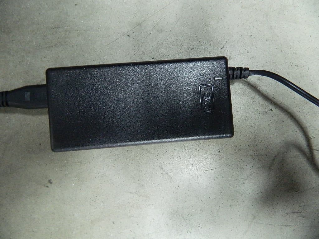
N6N2012061802HE
Aug 18, 2012VM-850Tx
Equipment Class
DCD - Part 15 Low Power Transmitter Below 1705 kHz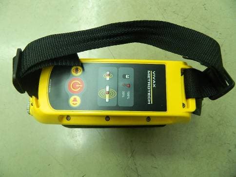
N6N2012061801HE
Aug 08, 2012VM-810Tx
Equipment Class
DCD - Part 15 Low Power Transmitter Below 1705 kHz