N6TSCACEJ
Chapman Technologies Inc.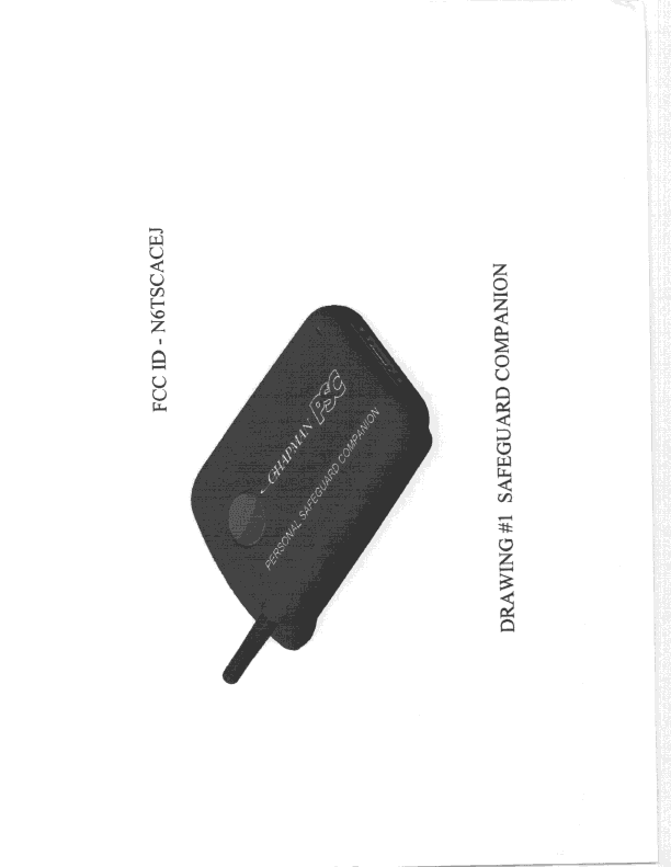
Click to zoom
Application Details
- Equipment Class
- TNF - Licensed Non-Broadcast Transmitter Held to Face
- Date of Grant
- May 23, 1999
- Application Purpose
- Original Equipment
- Date of Application
- Feb 02, 1999
- Frequency Range
- 824.04000000 - 848.97000000
- Company
- Chapman Technologies Inc.
- Country
- United States
Documents & Files
Document Text
Text extracted from the exhibit documents filed with the FCC. Open a document above to read the original.
RF Exposure Info
3D-EMC Laboratory Inc. Product Compliance SAR Test Report Product : CHAPMAN Model : PSC101AS007 FCC ID :N6TSCACEJ Reference no.:10032 3D-EMCLaboratory,Inc. for NEAR FIELD MEASUREMENTS 3D-EMC Laboratory Inc. TABLE OF CONTENT 1.1 SAR TEST REPORT.............................................................................................................................................3 1.2 PRODUCT COMPLIANCE TEST REPORT..................................................................................................4 2.1 GUIDELINES.........................................................................................................................................................5 LOCATION OF TEST.......................................................................................................................................................5 2.2 MEASUREMENT SYSTEM SPECIFICATIONS.........................................................................................5 2.3 TEST DESCRIPTION.........................................................................................................................................6 2.4 PHANTOM............................................................................................................................................................6 2.5 SIMULATED TISSUE..........................................................................................................................................6 PREPARATION..............................................................................................................................................................7 2.6 MEASUREMENT OF ELECTRICAL CHARACTERISTICSOF SIMULATED TISSUE...................7 DESCRIPTION OF THE SLOTTED COAXIAL WAVEGUIDE...............................................................................................8 2.7 SYSTEM DESCRIPTION....................................................................................................................................9 2.8 DATA EXTRAPOLATION................................................................................................................................10 2.9INTERPOLATION AND GRAM AVERAGING..........................................................................................10 2.10 POWER MEASUREMENT.............................................................................................................................11 2.11 POSITIONING OF D.U.T................................................................................................................................11 3.1 DATA......................................................................................................................................................................13 ANTENNAOUT..........................................................................................................................................................__ TEST INFORMATION...................................................................................................................................................__ ATTENUATION VERSUS DEPTH SCAN........................................................................................................................__ AREA SCAN CONTOURPLOT.....................................................................................................................................__ 3D PLOT OF ABSORBED ENERGY.............................................................................................................................__ ANTENNAIN..............................................................................................................................................................__ TEST INFORMATION...................................................................................................................................................__ ATTENUATION VERSUS DEPTH SCAN........................................................................................................................__ AREA SCAN CONTOURPLOT.....................................................................................................................................__ 3D PLOT OF ABSORBED ENERGY.............................................................................................................................__ SIMULATED TISSUE..................................................................................................................................................__ SIMULATED TISSUE TEST REPORT.......................................................................................................................__ 3D-EMC Laboratory Inc. SAR Test Report To:CHAPMAN Date:05/07/99 Re:10032 Radio Information Radio Type: PSC Model Number: PSC101AS007 Serial Number: 1004 Frequency Band(MHz)800 Frequency Tested(MHz)835 Nominal Output Power:(W) 0.600 pk / av Antenna Type:Helix Antenna Position:IN Signal Type:CW Duty Cycle:- Simulated Tissue Type of Tissue:brain Measured Dielectric Constant:44.6 Measured Conductivity:0.86 Conditions Robot:6 Axis Scan Type:SAR Measured Field:E Measured Power(W):0.509 (Compensated for Cable Loss) Phantom Type:head Phantom Position:right ear Room Temperature °C:23.5 Distance Antenna-Shell:8 mm Probe Probe Name:E Probe Orientation:- Probe Offset(mm):3.0 Sensor Factor:10.8 Conversion Factor:0.61 Calibration Date:3/24/99 Results Maximum Fields Location:X : 5Y : -35 Peak Voltage (mv):17.54 1cm Voltage (mv):10.06 SAR (averaged over 1 gram of tissue) W/kg: 0.77 Comments@ 825 MHz, Power 0.511 W = SAR 0.68 @ 849 MHz, Power 0.370 W = SAR 0.72 Insertion loss of adapter cable = 0.36 dB @ 824 MHz, 0.39 dB @ 835MHz, 0.50 dB @ 849 MHz (Measured by manufacturer) 3D-EMC Laboratory Inc. 4 Product Compliance Test Report Re:10032 Manufacturer:CHAPMAN Technologies Inc. Address:Fort Lauderdale, FL Product Description:Personal Safeguard Companion Product Classification:Uncontrol Based on t…
Text truncated - open the document above for the full version.
Test Report
TITLE: Test Report FCC-ID N6TSCACEJ FILE NAME: C:\Ready_To_Convert\Doc\37053.DOC FILE DATE: 05/12/99 9:07 AM Specification Number: TR101/100/002 Page 1 of 6Print Date: 6/26/01 FCC Type Acceptance Application ATTACHMENT TO EXHIBIT 4 TEST REPORT “Personal Safeguard Companion” 731 Confirmation Number: EA93547 FCC ID – N6TSCACEJ FCC ID – N6TSCACEJ TITLE: Test Report FCC-ID N6TSCACEJ FILE NAME: C:\Ready_To_Convert\Doc\37053.DOC FILE DATE: 05/12/99 9:07 AM Specification Number: TR101/100/002 Page 2 of 6Print Date: 6/26/01 CONTENTS 1OBJECTIVE.................................................................................................................................................................. 3 2ERP................................................................................................................................................................................. 3 2.1M EASUREMENT OF R ADIATED F IELD I NTENSITY ......................................................................................................... 3 2.2C ALCULATION OF ERP FROM M EASUREMENT ............................................................................................................. 3 2.3T HEORETICAL C ALCULATION OF ERP ......................................................................................................................... 3 2.4R ATED RF O UTPUT ..................................................................................................................................................... 4 3SAR................................................................................................................................................................................. 5 FCC ID – N6TSCACEJ TITLE: Test Report FCC-ID N6TSCACEJ FILE NAME: C:\Ready_To_Convert\Doc\37053.DOC FILE DATE: 05/12/99 9:07 AM Specification Number: TR101/100/002 Page 3 of 6Print Date: 6/26/01 1 Objective This Attachment to the Test Report refers to the measurements for ERP and SAR requested by the FCC in their correspondences of April 19 and May 03, 1999, Correspondence Reference Numbers 7269 and 7565 respectively. 2 ERP 2.1 MEASUREMENT OF RADIATED FIELD INTENSITY Radiated Field Intensity measurements were carried out at the FAU EMI R & D Laboratory, Boca Raton, Florida. The results are given in their Technical Report No. 99-032, which is attached to this document. The Chapman Personal Safeguard Companion uses a helical antenna. The measured maximum “peak” field intensity was 123.6dBuV/m, or 1.514V/m, at a distance of 3 meters. 2.2 CALCULATION OF ERP FROM MEASUREMENT Assuming Free-Space radiation, for a half-wave dipole in the direction of maximum radiation, the power density, P (watts/meter 2 ) due to the power radiated, Pt (watts), is P = 1.64Pt/4πR 2 Where R is the distance in meters. The electric field strength, E (volts/meter) and power density, P at any point are related by P = E2/120 π Hence, E 2 = (49.2Pt)/R 2 Or, Pt = E 2 R 2 / 49.2 For E = 1.514V/m, R = 3 meters Pt = 1.514 2 x 9 / 49.2 = 419mW Hence, maximum measured ERP is 419mW. 2.3 THEORETICAL CALCULATION OF ERP The Chapman Personal Safeguard Companion uses a short helical antenna with dimensions of: Height 0.66 ins, Diameter 0.144ins, Wire diameter 0.0245ins, and 13 turns. Using formulas for helical antennas given in “ITT Reference Data for Radio Engineers”, 1973, Section 25-11. Calculated Radiation Resistance = 1.39ohms Calculated Wire resistance = 0.31ohms FCC ID – N6TSCACEJ TITLE: Test Report FCC-ID N6TSCACEJ FILE NAME: C:\Ready_To_Convert\Doc\37053.DOC FILE DATE: 05/12/99 9:07 AM Specification Number: TR101/100/002 Page 4 of 6Print Date: 6/26/01 This gives an ideal efficiency of 66.7%. A Helical antenna has the same directivity as a dipole, hence, there is a 1.64 gain in the direction of maximum radiation. The conducted transmit power is controlled to be nominally 400mW by the ALC circuitry. Therefore, the maximum ERP, Pmax = 400 x 1.64 x 0.667 = 437mW In practice, the resistance of the matching components must also be added to that of the wire resistance. There are two series inductors in the matching network with a maximum resistance of 0.08ohm each. This reduces the efficiency to 55.8%. Thus, by calculation, the worst case, maximum ERP, Perp = 400 x 1.64 x 0.534 = 366mW Hence the calculated maximum ERP is 366 to 437mW. This agrees well with the measured result of 419mW. 2.4 RATED RF OUTPUT The conducted power output, out of the antenna terminal is nominally 400mW, set by the Automatic Level Control (ALC), as described in Exhibit 2, “Technical Information”, para. 5.3.4.2, of our FCC Application. The maximum measured value, at mid band, was 380mW. On Form 731 1.0W ERP was inserted in the mistaken belief that “Rated RF power output” referred to the maximum specification allowed for, which corresponds to –2dBW +2 –4dB, i.e. 0dBW. “Rated” was interpreted as being the level at which the equipment is capable of, similar, say, to a 1W rated resistor that is only actually dissipating 600mW in the circuit. The Personal Safeguard Companion (PSC) does not emit 1W under any conditions. Based on the above results, the “Rated RF power output, in watts”, Form 731Section IV, 8 (b), should read 450mW, corresponding to the maximum ERP. FCC ID – N6TSCACEJ TITLE: Test Report FCC-ID N6TSCACEJ FILE NAME: C:\Ready_To_Convert\Doc\37053.DOC FILE DATE: 05/12/99 9:07 AM Specification Number: TR101/100/002 Page 5 of 6Print Date: 6/26/01 3 SAR 3D-EMC Laboratory, Inc, Fort Lauderdale, independently tested the Chapman Personal Safeguard Companion. A copy of the “Product Compliance SAR Test Report”, reference 10032, with the measurements and Data, is provided to the FCC. The Personal Safeguard Companion (PSC) is fitted with a 1W loudspeaker and a sensitive microphone able to pick up conversation from up to 30 feet away. The unit is designed to be a “Hands-Free” device. In a vehicle, for example, the unit is placed in a bracket on the dashboard and stays in the brac…
Text truncated - open the document above for the full version.
Test Report
FCC ID: N6TSCACEJ EMI Research and Development Laboratory Department of Electrical Engineering Florida Atlantic University 3998 FAU Blvd., Suite 310 Boca Raton, Florida 33431 (561) 338-1650 Technical Report No. 99-032 “Radiated Field Intensity Measurement of the Chapman Technologies, Inc Personal Safeguard Companion FCC ID N6TSCACEJ Performed: 6 May 1999 Customer:Chapman Technologies, Inc. 800 W. Cypress Creek Road, # 240 Fort Lauderdale, FL 33309 Company Official responsible For product tested:Graham K Smith, Director of Systems Development Tel (954) 958 9000, fax (954) 958 9009 Test Performed & Reported by:J.R. Nicholson FAU EMI R & D Laboratory Approved by:Vichate Ungvichian, Ph.D., P.E. Director, FAU EMI R & D Laboratory FCC ID: N6TSCACEJ 1.OBJECTIVE The Chapman Technologies, Inc. ‘Personal Safeguard Companion’ #1021 was measured to determine the maximum field intensity level radiated at fundamental frequency. The results reported in this 2 page document apply only to the specific items of equipment, configurations (including software/unit operation), and procedures supplied to the Florida Atlantic EMI Research Lab by Chapman Technologies, Inc as reported in this document. 2. TEST PROCEDURES The measurement techniques identified in measurement procedure ANSI C63.4-1992 “American National Standard of Measurement of Radio-Noise Emissions from Low-Voltage Electrical and Electronic Equipment in the Range of 9kHz to 40 GHz” were followed as close as practical during this evaluation. Complete details and specific procedures used are discussed in the following paragraphs. 3. RADIATED EMISSIONS The ‘Personal Safeguard Companion’ unit was set up on a wooden turntable 80 centimeters above the ground plane floor of the FCC listed Semi-Anechoic test site. Radiated emission measurements were performed with the unit positioned on its foot, with the antenna in the vertical upright position. N EMCO 3121 Tuned Dipole DB-4 s/n 1011 Antenna was installed on an EMCO pneumatically controlled Antenna Mast at a distance of 3 meters form the unit. The unit, transmitting at full power through its normal antenna at 834.580MHz, was observed for maximum radiated emission levels on a HP 8566B Spectrum Analyzer (1 MHZ res/vid bw, freq span 500 kHz, through a Quasi-Peak Adapter, for a final bandwidth of 120 kHz). The turntable was rotated through 360 degrees, the antenna was scanned in height from 1 to 4 meters in both the horizontal and vertical polarizations and the “peak” induced voltage (dBuV) plus cable loss (4.3 dB) plus dipole antenna factor (27.6 dB) resulted in the following “peak” field intensity levels. DIPOLE POLARITYFOOT HORIZ119.0 dBuV/m VERT123.6 dBuV/m This data shows a maximum “peak” field intensity level of 123.6 dBuV/m or 1.514 Volts per meter a distance of 3 meters.
Contact Information
Applicant
Graham Smith(Director of Systems Development)
Technical Specifications
| # | Rule Parts | Frequency Range | Power Output | Emission | Tolerance |
|---|---|---|---|---|---|
| 4 | 22 | 824.04 MHz - 848.97 MHz | 450.00 mW | 40K0F1D | 2.5 ppm |
Other Applications from Chapman Technologies Inc.
N6TVLACES
Mar 29, 2000Chapman Vehicle Locator
Equipment Class
TNB - Licensed Non-Broadcast Station Transmitter